Requested sample clock source is invalid wls-9163
My goal is to use two accelerometers that using the NI 9234 entry of the modules and wireless wls-9163 chassis.
My program is attached. Here is a photo in case you do not want to download the attachment: http://www.imagebam.com/image/577a4a195651371.
The slave device is not able to use the sample clock that came out of the master on PFI1.
I looked through the wireless DAQ resource kit and watched the following video:
http://www.YouTube.com/watch?v=g_8jiKuKeDI
and ive read this: http://zone.ni.com/devzone/cda/epd/p/id/6124
I am aware that
I also tried to synchronize two cDAQ-9178 using the same methods. I always get the error "required sample clock source is not valid.
The manual says it should be able to do this
http://www.NI.com/PDF/manuals/372488c.PDF
Any help would be greatly appreciated.
Vexis,
Unfortunately, at the moment, you cannot synchronize the modules that use adelta-sigma converter (such as the NI 9234) in several cDAQ chassis. This is because these modules use a clock of sampling, which is very high; the PFI lines are unable to return to the required sample clock. You can share the start triggers, but the clocks of individual modules will drift over time.
The reason that the error message says that "requested the sample clock source is not valid" is because these modules require the use of a sample of clock that comes inside a time base clock oversampling.
Sorry for the bad news!
Katie
Tags: NI Hardware
Similar Questions
-
Hello
I have a small question on an example of clock by RTSI source.
In my configuration, two PCI cards (PCI-6602 (dev2) and PCI-6110 (dev1)) are connected by a RTSI cable.
I would like to build a clock on 6110 source sample and use it on 6602 counting external impulses of entry.
In the MAX test Panel, I checked that a meter was reading of external signals.
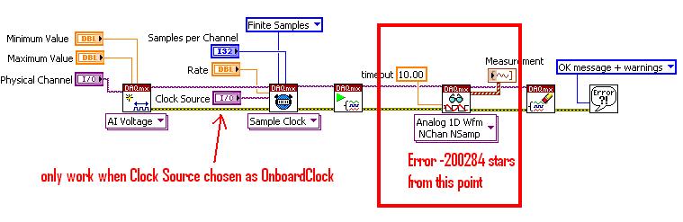
However, the vi attached do not work, and the whole County, and then give an error of 200284.
Could you tell me what is the problem?
I guess that something is not right on the clock signal routing. I have to use DAXmx connect terminals vi instead of external signal?
How can I check that both devices are connected through a RTSI cable?
I recorded the cable and connected devices on MAX with no problems. Is this enough?
Thank you for your comments and kind suggesion.
Several things briefly:
- Must match the orientation of the RTSI cable. Connectors are generally indexed to ensure this, but if you use a cable in water House, just keep it flat between the boards.
- The code you posted attempts to use the time base internal 20 MHz as a sample clock. That will not work for several reasons, and the fact that you try suggests you may have a poor understanding of the functioning of the meter. You do * not * need to "sample" at a pace high in order to catch the digital transitions. The meter circuit manages everything in the material. What you "sample" in a task of counter is a County registry value. Digital TTL edges which are worth little matter how many times you "sample" it increases.
- I suspect you want to * account * cycles of the clock of the signal of your 6110, be it a train of pulses counter or a sample clock based on the tasks.
- I am writing an example that does without buffer sampling clocked by the software, to approximately 10 Hz. Dev2 uses to generate a pulse of 1000 Hz and uses Dev1 train to interrogate the County registry value in a loop. It is simple from the code you posted to help unravel the special problems of routing RTSI config problems. Start using something simple like this to see if DAQmx succeeds routing signals through RTSI.
-Kevin P
-
None of RNS, te0 & te1 clock source work except OnbordClock for cDAQ9174?
acquisition system used: cDAQ-9174, NI9206, Labview2009, OR-DAQmx 9.2, MAX 4.7.1
Referring to the "specifying different sample rates for CompactDAQ Modules multiple", following time engines could be used for cDAQ9174 (AI, te0 & te1)
/ cDAQ1/I/SampleClock
/ cDAQ1/TE0/SampleClock
/ cDAQ1/TE1/SampleClock
However, for the voltage-Clk attached Acq Select.vi, none of the above clock works unless OnbordClock is selected. Can someone explain this please?
Hi NCLbingji,
'Source' entry "DAQmx Timing (sample clock) .vi" tells DAQmx to get the sample clock a PFI PIN or another subsystem (such as AO, DIO or counters). It has not been designed to choose what sync engine to use. I think that the example of the community that you mentioned is defining the sample clock source incorrectly.
On a device with a single timing engine of HAVE, like cDAQ-9172, ' IA/SampleClock' by specifying the source of the sample clock I tells DAQmx to deliver the sample clock GOT to the sample clock, which he cannot do it, then it gives you a more useful error:
"Error-89131 occurred in DAQmx start Task.vi:8 '.
Possible reasons:
Attempted to perform an itinerary when the source and destination are the same terminal.
In many cases, like when you configure an external clock or counter source, you must select a PFI, PXI or RTSI trigger line as the terminal of the source.
Property: SampClk.Src
Property: SampClk.ActiveEdge
Source device: Dev1
"Terminal source: AI/SampleClock.A cDAQ-9174, DAQmx chooses the timing engine when you book the job. The timing engine he chooses does not necessarily match the timing engine that you specify in the VI. If it does not match (for example your VI specifies te1/SampleClock, but DAQmx choose te0), then your task will wait for Terminal produce some clock pulses. Because there, there is no clock on this terminal, the task eventually times out and returns the error-200284 (samples not yet available).
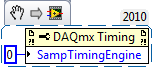
The correct way to explicitly specify what sync engine to use is to set the SampTimingEngine property.
Unfortunately, the table of values for this property by using NOR-DAQmx for 9.2.x version is also incorrect (reported to R & D such as CAR #239502). Here are the correct values:
- 0 selects te0.
- 1 selects te1.
- 2 selects HERE.
You can also leave DAQmx choose a timing engine, then ask that you chose. To do this, choose the task and then get the value of the SampClk.Term property.
Brad
-
WLS-9163 and 9211, sampling frequency of evil?
Hello!
I have a WLS-9163 with 9211 mounted module. I have connected a single thermocouple type K to the analog input 0.
I can connect and perform measures wireless. However, I can make only 7 s/s without error message.
I get the following error message when I try to taste 14 s/s in the configuration of WLS-9163.Error-200081 occurred to the DAQ Assistant
Possible reasons:
Sampling frequency is greater than the maximum sampling frequency for the number of specified channels.
Reduce the sampling frequency or the number of channels. The increase in the conversion rate or reduce the period of the sample can also mitigate the problem, if you define one of them.
Number of channels: 2
Sampling rate: 14.000004
Maximum sampling frequency: 7.142857
Channel name: _WLS-14049AF-2/_cjtempWhen I use the 9211 in a cDAQ-9172 configuration I can acquire up to 14 s/s of a single channel with no problems at all.
Somehow he thinks that I chose to take measures to channels, that is not the case.
I use Labview 8.5.1 with hardware drivers of 2009-10 with Windows XP SP3.
Is this something you've heard before?
Best regards
MattiasMattias salvation,
Your task is also reading the CYC on the unit once for example, if you are done reading of two channels. Reading of the CCM (it's the .../_cjtemp in the error message) is required to return a value of temperature measured from a thermocouple.
Kind regards
Kyle
-
Synchronization of analog and digital output with the external sample clock
Hello
First of all sorry for my English, I will try to explain what I want to do.
I want my PCIe-6321 to send two custom signals (modification sawtooths) on a mirror controller. I would also like to generate output with my card at the beginning of each tooth of saw. Everything must be synchronized with an external k-clock signal of 100 kHz. The idea is that whenever the PCI receives a trigger to external clock, it sends two analog output voltages and when he received 1024 clock ticks it will also send a pic of triggering TTL. What I do is first prepare the map and after that in a loop sending and modifing the output values of the two signals and at the same time send a digital signal Boolean in each arch, so when's done it 1024 iterations of the loop I send an event to the digital port. Attached you can see.
The problem is that I don't know how to synchronize both. Can I use the sample clock just to the analog output? I can use sample for the two outputs clock, or do I need to use the output of the meter? If don't know how to use it here.
If I do nothing else bad/wrong, I would be grateful for feedback.
Thanks in advance,
PabloI don't know how but I find the solution. I'm generating more than a positive value (as I was triggered maybe very fast the oscilloscope has been absent there). If I put the sample clock of digital output to use the sampling/ao/Dev1 clock that it doesn't, but if I put to use the same source as the OD (terminal where my external clock is connected), but the trigger to start the DO to be Dev1/ao/StartTrigger this works. I don't really know why, but it does.
Thank you for your patience and your help. I put here the final code.
-
External sample clock change takes a lot of time on the SMU-5186
Hello
I use the external Lv - niScope EX Clocking.vi example to define SMU-5186 using an external sample clock. However, it takes a long time, 5-6 minutes, before I can get the first block of data acquisition.
Then I run the example 'niScope EX Acquisition.vi Configured' to switch to dashboard clock. There are also 5 to 6 minutes on the first acquisition.
I think maybe the SMU-5186 made some calibration when I change the source of the clock.
Anyway is to ignore the calibration? Or make it faster?
Thank you very much
Yiming
Yiming,
Delays in acquisition are caused by calibration routines that must be performed on the engine to sample (ADC) every time that changes sampling rate. This ensures our justified precision specifications.
I don't know if you've noticed also calibration of Power-Up, which will take 5-10 minutes to complete when the unit is turned on. This is mentioned in our specifications at page 18:
http://www.NI.com/PDF/manuals/373257b.PDF#page=18
I hope this helps.
Nathan
-
Problem with DAQmx Schedule VI (sample clock)
Hello to you all,.
I'm new to this forum, please bare with me. I have some experience with LV, but I am relatively new to data acquisition projects. I use LV2009.
I want to make sure that I use the hardware timing (instead of software distribution) in my project so I followed some of the threads here as sugested to use DAQmx Schedule VI. The problem is that no matter how I set the system I get the same error-200300 invalid calendar
type.The project is simple. I encode with 1000 pulses per
Rev and it is mounted on a shaft of a turbine water goes thru. I'm watching the frequency
and so the rotation of the shaft which tells me that the amount of water flows through the turbine. In the end, there will be 2 channels
by every encoder and ~ 3 encoders (turbines) total and calibrated the main meter that will give me constant impulses and all encoders will be compared to this master frequency.I'll use PCI6602 DAQ, but
now, for the development, I use USB6221. Let's say that the
frequency is between 500 Hz and 10 kHz. What I am doing wrong? Or maybe better to ask - what would be the right approach for this project?Thank you
Marty
Hi Marty,
It seems that your question is already answered here, but Jason is correct that the 6221 neither the 6602 support a clock sampling for frequency measurements.
As Jason mentioned, your best bet is also likely set the mode of synchronization for "implied". This means that the frequency value is sampled at the end of each period of your input signal. In addition, a solution that is clocked by the software (On-Demand) might be acceptable.
X Series DAQ devices allow an external sample clock to use for frequency measures (described in the Manual of X series). Frequency of sample-clocked measures are useful in very specific
circumstances, but it does not seem that you need this feature based on what you've described so far.(621 x) bus-powered M series can also be configured to use an external sample as the X series clock but do you not have the same features described in the manual of the X series.
I hope this helps!
-John
-
divide the internal sample clock (VCXO)
Hi all
I want to divide clock source internal sample of my high-speed 5122 digitizer PXI card.
5122 PXI, 200 MHz internal clcok source example. I want to taste my data at 10 MHz.
So I want to divide down the clock of internal sampling by a factor of 20.
I want to do it programmatically.
I have found no vi node or property for that (although found the node property for entry divider OR worn... but which has been used only for reference for on-board clock clock)
Help me as soon as possible...
Hi Jirav,
I just wanted to clear some things. The 5122 has a sampling rate 100 MECH's maximum real-time. / s (not 200 MHz as you originally suggested). To obtain a rate of 10 MHz, you would be divided down by a factor of 10. From page 13 of the document specifications NI 5122:
Just to add to what Henrik suggested, the following help topic describes the specific VI to configure horizontal properties such as the sampling frequency, he mentioned:
http://zone.NI.com/reference/en-XX/help/370592P-01/scopeviref/niscope_configure_horizontal_timing/
Most of the expedition OR SCOPE examples use the VI above and there is an entry for "min sampling rate" where you can simply specify the value "10 M" or '10000000' to get the device of sampling at a lower rate.
Note: because the digitizer allows only sampling frequencies which are an integer divide down the maximum sampling frequency, rate will always be forced to match up to the second tier legal sample. For example, if you specify '9.8435 M', it would automatically force the rate up to 10 MHz. To display the actual value that the scanner is used, you can query the property node "Actual sampling frequency" at any point in your code after the configurations have been committed digitizer. The help manual describes this property on the following page:
http://zone.NI.com/reference/en-XX/help/370592N-01/scopepropref/pniscope_actualsamplerate/
Kind regards
-
sample clock adjust external trigger
I am trying to use a source of external trigger non - TTL (square wave ~ 8 kHz from 0 to 1.4 V instead of 0 to 5 V) as the clock for an analogue waveform output voltage. Is there a way I can manually change the threshold used for the clock source so that I can get this working?
I'm trying to avoid having to solve this problem at the hardware level, which in my opinion, is to build a comparator circuit to generate a trigger signal TTL of my 0-1, 4 a signal trigger V square.
If not, is there a way I can generate a TTL signal that is synched to my trigger signal 0 to1.4 V ~ 8 kHz wave square using these maps NOR: PCI-6115 or PCIe-6323?
Thank you!
Cecinix, you are right. The sample of the signals clock are specified to be TTL signals, which means that the minimum thresholds of high voltage on the PCI-6115 and PCIe-6323 are respectively 2.2 V and 2,0 V. Digital/PFI input thresholds are listed in the data sheets of the devices, so that they are material defined. Unfortunately, given that all the digital inputs on the card you mention expect tensions TTL, it's something that you have to fix in the material. A comparator circuit could operate as a network of transistors of pull-up.
What generates the square wave? Would it not viable for generating a signal of TTL clock on your NI DAQ card and export this signal to the rest of your system? In general, a digital system is quite tolerant of extra tension a bit, so it's maybe easier than adding voltage conversion circuits.
Kind regards
William R.
Technical sales engineer
-
I use an analog input on a PCI-6224 and are having problems with the clock source
I use an analog input on a PCI-6224 and are having problems with the clock source. I'm trying samples of 16 different analog inputs very quickly. I have the sample mode: Timed Single Point material. The rate, that I am running is the maximum (250 kHz (15625Hz per channel)). I left the default clock source and trying to taste several times. The analogue input works for a short time (2-3 seconds) and then everything stops. I'm doing something wrong or is there something I'm missing? Any advice would be great.
That's how you samples using the sample clock clock. If you see a delay then something is wrong with how you track/data visualization.
Single point NI the hardware is for PID control with a real-time operating system.
-
How the PFI to go top-to-bottom with sample clock?
Hello world!
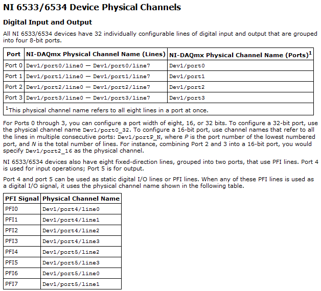
I am very new to LabView and I try to do something very simple in the NI PCI-6534 and still not get anywhere (or do not know if it is the limitation of the hardware)
My request is to acquire digital data of 2 channels (16-bit each) of our Board custom designed analog-to-digital.
So far, I am in a position to acquire a finite amount of sampling digital (say 100000) and using a trigger to start (PFI6) to start the acquisition of our custom card board. Just to let you know that I'm feeding the PCI-6534 an external clock of 20 MHz by PFI2.
However, I want to send a signal to trigger recognition (high/low-rising edge) to our personal advice, saying: he did the acquisition of 100000-sample.
My problem is that whenever I try to use the lines of PFI signal with an internal sample clock, I get an error saying that I can't use the PFI lines with any sample clock. But my goal is to use a rising edge (low-high) to trigger back.
So far, I can pull the PFI4 high and used a timer to make it low. But the resolution of the timer is milliseconds (software) range. I would like to have at least a few microseconds.
I also tried using implicit since manual said that it does not require any clock but still get no result. Also, I couldn't find an example of implied clock and don't know if PCI-6534 supports.
Note that I'm able to use the clock synchronization of sampling with other DIO (Port 0 to Port 3) lines and get the result I want. However, I would need to use all our custom Board 32 - DIO for analog-to-digital data lines. So, using the line of PFI laccuse is the only choice.
If you have ideas/pointers, please throw it at me, I'll try them. Thanks a lot for your help!

See you soon,.
Yaseen KhanHi ykhan,
After validation, I noticed that it will not really work for what you are trying to do. The PFI lines on your 6534 are I/O static only as shown in the DAQmx help.
You will be able to control these lines, but only with software timing. You should be able to call and argue by their physical channel name. I hope this helps!
Kind regards
-
An external sample clock between sharing arrangements
I need to acquire samples of 2 separated Renault M series (PCI-6254). My master device receives a sample of 8 on PFI0 KHz clock. Is it possible at the root of this clock of the master to the slave via a RTSI cable device?
I looked through the forum and the sample programs, but have only seen examples in which the master clock on board the aircraft happened to the slave.
It is possibe to synchornize device slave the master clock to external sampling of the device?
Thank you
ANT1
ANT1,
Fortunately, most of the time something that can be done in DAQmx in LabVIEW can be done in ANSI C using the appropriate function calls. I have listed the following steps of the program example LabVIEW and retouched to remove anything that it is not suitable for the DAQmx configuration. I'm sure it should work for you.
Steps to follow:
1 create a channel of analog input voltage for the master and the slave.
2 set the synchronization parameters. For the master, select the source of the external sample clock. Set the source AI/SampleClock of the master for the slave device. (Note: sample of the master clock is automatically routed through the cable RTSI.)
3. for the slave, set the Source of the trigger to the AI/StartTrigger of the master device. This will ensure that both devices start sampling at the same time. (Note: the trigger is automatically redirected via the RTSI cable.)
4. call the start task to start the acquisition. (Note: start slave task before the master task.)
6. read all waveform data.
7. call the clear task to stop the acquisition and clear the task.So, essentially, the value of the task of the slave to the top in the same way as you would for the synchronization of clocks on board, but configure the task to master as you would for an external clock. This will automatically share the external clock and trigger on the line of the RTSI.
-
Some or all of the requested samples are not yet acquired: API change responsible?
My Delphi program, which works very well under NOR-DAQmx 8.9.0f4 on a set of material, fails under 9.0.0f2 on what I received insurance material is equivalent. The error is «some or all of the requested samples are not yet acquired...» ». This happens even to slow scanning rates, and coming to suspect that the API has changed subtly in the transition from version 8 to 9. What is the probability is it? Now that I have access to the source code on the new hardware (NI PXI-1044 with computer integrated PXI-8110) is there something I can do to check this?
Hi Francis,.
Your program still calls DAQmxCfgDigEdgeStartTrig() for all the tasks of the slave? If you do not do this, the devices are beginning to acquire data at the same time, and since you pass 0 for the timeout parameter to DAQmxReadBinaryI16(), out-of-sync devices could certainly time-out errors.
In addition, you must ensure you start the slave devices before the master device, so that they're already waiting for a trigger at the start of the master device.
Brad
-
sample clock 6551 exporting to PXI_STAR
Hello
The help files for the x 655 (devices-> NI 655 x-> hardware-> Signal Routing Architecture) is a chart that shows the 6551 as source's internal sample clock and the PXI_STAR as a destination. I tried to implement, but it is back with a runtime error stating that the material doesn't have this ability. I have the 6551 in slot 2 the PXI backplane. Am I misunderstood the routing table in the help file.
Part of the code...
Configure the internal clock generator to be Meg 2
ErrChk (niHSDIO_ConfigureSampleClock (* viGen [out_card_number], NIHSDIO_VAL_ON_BOARD_CLOCK_STR, 2.0e6));
export the sample clock on co - ax signal clock
ErrChk (niHSDIO_ExportSignal (* viGen [out_card_number], NIHSDIO_VAL_SAMPLE_CLOCK, VI_NULL, NIHSDIO_VAL_PXI_STAR_STR));
make a commit to start the clock output
ErrChk (niHSDIO_CommitDynamic(*viGen[out_card_number]));Thank you
Andrew
Hello Andrew,.
The documentation is in fact inaccurate. Only certain devices can actually lead the line PXI_STAR as destination and 655 x devices cannot. It was a mistake in our documentation and has been reported to R & D under ID #166056. I believe that the following devices can lead the line slot of two PXI_Star:
- PXI-4461
- PXI-4462
- PXI-4472
- PXI-4472 b
- PXI-4474
- PXI-5112
- PXI-7344
- PXI-665 x
- PXI-6682
Please let me know if you want to use one of these devices and we can have a person from their product group check that they will be able to lead the line PXI_Star.
Kind regards
Paul C. -
Problem with vacation request sample for SOA deployment
Hi all
I'm having some problems with deployment of vacation request sample for SOA Suite 11 g and was hoping that someone here could help me. I'm a newbie with all this stuff.
First of all to tell you what I've done so far. I installed on my local machine Oracle XE 10g on Windows Vista.
I have followed through all the requirements of SOA Suite 11 g installation on my local machine (UCR crossed, I ran Configuration Manager to configure WLS on the local computer, installed jDev plugin to work with SOA etc.).
Everything went well until I tried to deploy this app on WLS.
Generation SOA went well but I have error when you try to deploy:
Deployment - journal:
[15: 39:09] > > > > WARNING: unable to determine the platform target profile. Using default...
[15: 39:09]-deployment began. ----
[15: 39:09] the target platform's (Weblogic 10.3).
[15: 39:09] analysis of the dependence running...
[15: 39:09] building...
[15:39:25] deployment of profile...
[15:39:25] update of the review for the project SOA "VacationRequest.jpr" id to ' 1.0'...»
[15:39:25] wrote the Archives Module to E:\Documents\JDeveloper\SOAwork\VacationRequest\VacationRequest\deploy\sca_VacationRequest_rev1.0.jar
[15:39:25] # incomplete deployment. ####
[15:39:25] no SOA configured server found to deploy archive file:/E:/Documents/JDeveloper/SOAwork/VacationRequest/VacationRequest/deploy/sca_VacationRequest_rev1.0.jar
(oracle.tip.tools.ide.fabric.deploy.common.SOARemoteDeployer)
Since Oracle Enterprise Manager I can see that AdminServer and soa_server1 are running (bam_server1 isn't). But in tab 7 deployments are increasing and 14 are declining. These stockings are:
Name | Goal
-Resource adapters:
AqAdapter | soa_server1
DbAdapter. soa_server1
FileAdapter | soa_server1
FtpAdapter | soa_server1
JMSAdapter | soa_server1
MQSeriesAdapter | soa_server1
Application DeploymentOracleAppsAdapter | soa_server1
OracleBamAdapter | soa_server1
SocketAdapter | soa_server1
___________________________
b2bui | soa_server1
composer | soa_server1
DefaultToDoTaskFlow | soa_server1
Thanks for the help!For some reason your installation seems to be corrupted.
Server SOA is looking for its mandatory application, which is not able to find. I don't know, why the server is by looking at your file jdev for these applications.
When you set up the field, chose the model SOA of ORACLE_HOME, or JDEV_HOME?
You can try the rest of this http://www.installationwiki.org/Installing_Oracle_SOA_Suite_11gR1?
Nodemanager is necessary if you want to start your WLS Console/EM servers. Since you started from command line, this is not necessary in this case.

Maybe you are looking for
-
My HP Photosmart Plus B210e printer will not print black ink, only gray/color.
My printer HP Photoshop more faithful 210th has stopped printing in black ink last week. It prints color beautifully, but where there should be black it comes out just as gray or white spot. I have tried two new ink cartridges, cleaned print heads, r
-
I remove SP3 it works very well to reinstalled sp 3 and had the same problem
-
Writeback failed re c: documents and Settings.
I have Windows XP SP3 Home and an external hard drive that contains daily backups only. I've been backup top for almost 2 years and for the first time, I had a problem because I've indexed to enable research on this subject. "Windows could not save
-
I am trying to burn a cd and tell it to put in a blank cd. They are new disc, what can be the problem?
-
Remove the old connection & Security servers
Recently, I created a login replication server and a secondary security which are interconnected server.I seek to dismantle and remove the old servers, should be just the following steps?VMware KB: Remove a standard (replica) connection to the server