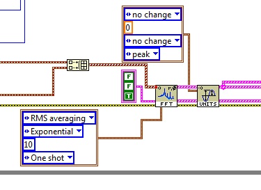
Rms vs pk scale FFT
I have a program that takes an accelerometer waveform data. Finally, I would like the g's pk units, but in the fft itself, I get a cleaner signal by the RMS. It's the same thing taking the g RMS and then by converting it to g's pk without calculation of the average initial?
Tags: NI Software
Similar Questions
-
Hello
I have a sinusoidal signal that oscillates around zero the axis in the negitave and positive. It is to measure the height of the waves on the static water level in a wave tank. I am calculating the FFT but the amplitude is less than the height of the waves in the time domain. Does this mean that I'm the wrong calculation? I don't know wheather I should use the FFT Peak or RMS? I assumed that the amplitude of the FFT should give me the same amplitude as the time domain.
Any advice would be greatly appreciated.
Thank you
Donners,
It can get complicated, but I suspect that what you see is the result of the frequency of the waves is not not exactly at the frequency of the FFT bins. For example, suppose that df = 1 Hz. Then each element of the array FFT represents the energy in a "sandbox" a hertz wide centred on the frequencies of the integer. For a wave with most of his energy to 7.3 Hz TFF likely values not null for trays Hz 7 and 8. In real systems with noise and light frequency variations, it is not uncomon for data can be spread over 10 or 20 locations. To get the fundamental signal amplitude, you would need to combine the energy in all stores. Since the FFT produces complex output, the phase component must also be considered. Non-sinusoidal Waveshapes means that part of the energy is in harmonics. A pulse square can have a large enough amplitude, but there's still no broad spectral components.
The short answer is that generally there is no easy way to get a precise correlation between the amplitude of crete in the time domain and the amplitude of spectral components in the field of the freqeuency.
Lynn
-
Why the FFT spectrum gives values of RMS?
Dear Sir
I want to get the value of crete to crete on FFT spectrum. But he gives values of RMS. Can you please guide me how can we peak to peak on the FFT spectrum. Attach the vi is for example.
Kind regards
Urfee
Tronoh wrote:
Dear Sir
I want to get the value of crete to crete on FFT spectrum. But he gives values of RMS. Can you please guide me how can we peak to peak on the FFT spectrum. Attach the vi is for example.
Kind regards
Urfee
What does it mean to get the value of Ridge Crest of a FFT spectrum? [I understand getting the value of P - P of the signal ...]. Note that the parameters on the average you attached (which shows mean quadratic value, by the way) refers to the way in which the Spectra will be averagedand RMS is logical (logical) in many cases, but I'm at a loss to understand the average peak-to-peak here...
BS
-
Using FFT to palette spectrum Subvi Interface of FPGA functions
Hello
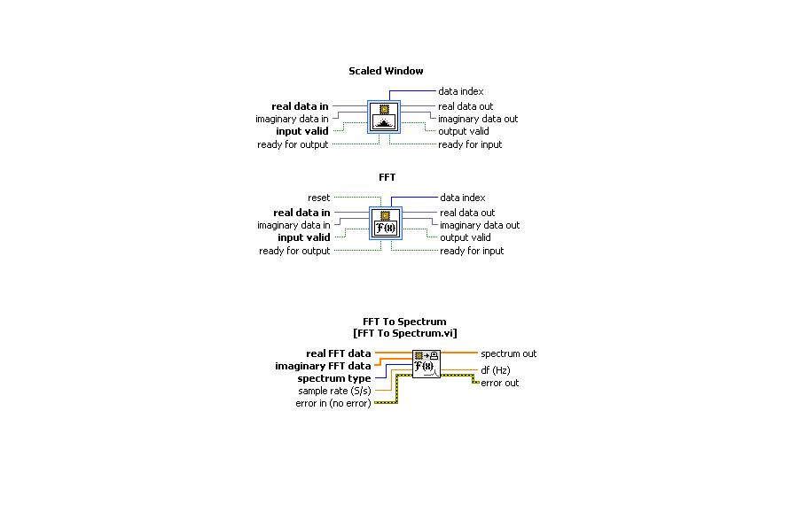
I use the card PCI-5640R and PXI-5600. I want to use the "scale" and "FFT" exspress screws to the range of functions 'Mathematical FPGA and analysis' in my VI "FPGA VI" and "FFT spectrum for '"FPGA interface"in my"host VI.
A poster of the code examples in which these three subVIs are used can.
Thanks in advance.
Kind regards
Rashid
Hi rachid,.
There are two examples of delivery here: LabVIEW 2009\examples\R Series\FPGA Fundamentals\Analysis and Control\FFT\
Jim
-
Why Express PSD gives a different result of amplitude as FFT PSD?
Hello
When I use the express VI of spectral measures to trace the power spectral density, I get a different result than when using the FFT PSD VI. The data are the same but the amplitudes are different in the PSD plot. Everyone comes through this?
Thank you
Donners,
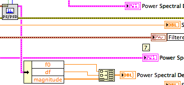
The PSD2 and graphic PSD2 are different because you are breastfeeding two extra points in the tables (t0, df). When graphic entry of data in the tables, they interpret not automatically information of t0 and df. Actually they do not yet receive this information. You must program the scales with nodes of property. If you simply draw the order of magnitude, the spectra are very similar.
^ ^ ^ This confuses only the chart!
The spectral forms differ slightly as the power spectrum of FFT and PSD.vi uses a default Hanning window.
Lynn
-
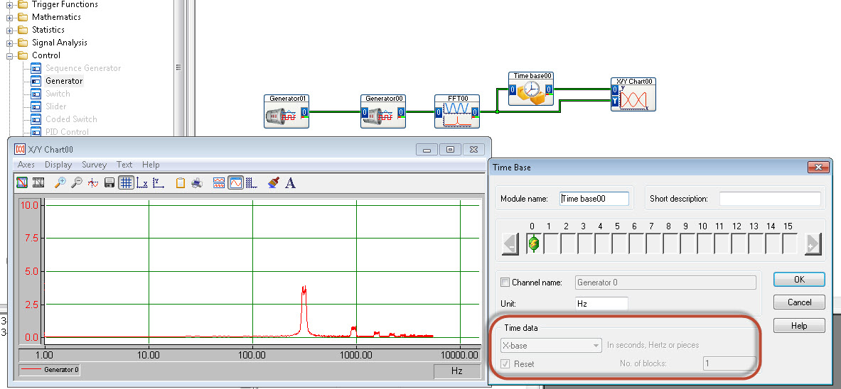
FFT to display with newspaper frequency axis
Hello
I'm trying to get my fft to display frequency (x axis) with a logarithmic scale.
There is no option for this in the table y/t
The xy graph has possibility of HRT, but I cannot "demux" the fft output signal successfully.
I use DasyLab 12.
Someone at - it ideas?
Thank you
Matt
Use the time Base module (special offer) to extract the x axis out of the block of the FFT.
-
FFT and differ from the values overall btwn VI and tiara
Hi all
I have an application that displays live readings of vibrations which the spectrum and the overall vibration level. Everything my generation of report is made in the DIAdem scripts, so it is essential that all values calculated and displayed on the side of LabVIEW are the values calculated and reported in DIAdem. The VI and Script, when the entrance to the PDM attachment, attached give me values significantly different to the size of the FFT and the overall value of RMS. Can anyone spot what I'm doing wrong?
Thank you
Scott
Hello
This is an excellent response of R & D. I felt that it would be better to put it on the web, then keep it limited to your service request.
The difference has to do with the window of correction. The results are the same if you choose rectangluar (or not) window.
Usually a window takes a share of the singnal away, so in the first place, the result has a different shape and is smaller compared to train with rectangular window. This can be fixed with a specific factor for each window.
There are two possible corrections. Random and periodic.
-Periodic is used if you have pure sinusoidal signals and you want to measure the peak value. A typical use case is the window of flattop is designed for this type of calculations. The periodic correction is too great if you want to add values to calculate the total RMS signal or the sum of a certain frequency band.
-Random is correct the signal back to the correct overall RMS value and must be used in all other cases.
The periodic correction for Hanning window is a factor of two. The correction is randomly about 1.633. Tiara will give the same result as LabVIEW if you use the following type of correction:
FFTWndCorrectTyp = "periodic".
In the world of the FFT analysis, the different corrections are very often not obvious and hidden to the user. Unfortunately, it is also the case in LabVIEW. You can find a good example of explanation here:
http://blog.Prosig.com/2009/09/01/amplitude-and-energy-correction-a-brief-summary/There are different factors for different window functions. If you go further in the FFT - VI you will find "window scaling VI. It has a «constant window» output With this, it is possible to obtain the correction values for window functions.
I think also, periodical is false in most cases, when Hanning is used, because Hanning is the best for the sum of the values of the RMS in the frequency bands and the results are bad without a correction at random.
Hope that helps.
-
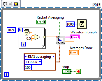
What does not restart in the FFT functions way?
Hi all
I would like to know what that "restart average" made for the FFT functions. According to aid,"reboot on average indicates if the VI restarts the process chosen medium." If restart on average is set to TRUE, the restart of the VI the selected with an average of process. If reboot on average is set to FALSE, the VI does not restart the process chosen sprawl. The default value is FALSE. When you call this VI for the first time, the averaging process restarts automatically. A typical case when you need to reboot on average is when a major change of entry occurs in the middle of the averaging process"
I realized that the FFT function takes in an array of values and perform the FFT on it. If the FFT function keep a buffer previous values and clears when restart average = true? Because the FFT functions are not Point by point and they take both in all the data to deal with, "a major change of entry occurs in the middle of the averaging process" can be true?
Thank you!
Sigh. I really tried to explain what was going on (probably) with this function, you use (and, I thought naively, you understand), but you got me wrong.
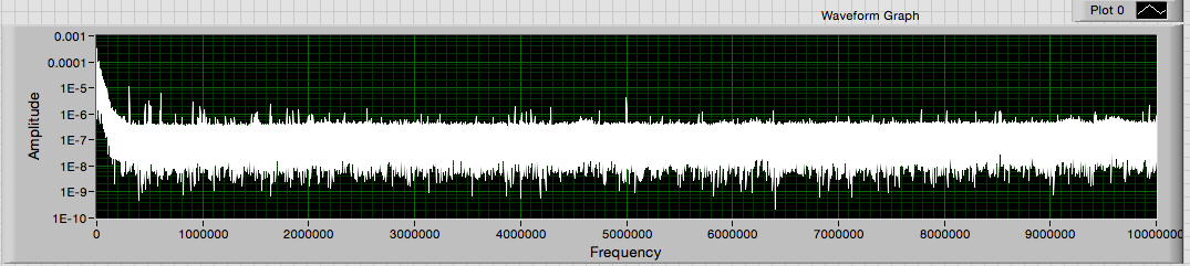
This VI creates a zero average noise signal, providing 1024 points per second. Do you know what should be the power spectrum of the signal? Due to the randomness of the input signal, the power (for a small finished sample) spectrum will also have a random component. If you had several ghosts of power on average, the average would begin to converge with the expected for random noise power spectrum.
If you run this VI and look at the Spectra resulting (on average), you will notice that the first spectrum is the most "spice" and that spectra are averaged, the variation is reduced and diminishes the value of crete (shown by looking at the scale of Amplitude). At any time, you can press "Reset average" and see this... reset the average, the following spectrum shows the growing nose, etc.
It shows the right way to test the function of the power spectrum and discover what he does. My suggestion as to what makes this function seems to be largely correct.
Bob Schor
-
PCI-6110 - calculated resolution RMS
We have a requirement for the resolution of measurement of voltage AC RMS. I am in a position a repetitive alternating signal with 512 samples on 1 cycle using the range full scale. I then calculate the value of these data. What is the effective resolution of the RMS measurement? Should not 512, 12-bit samples (signal varies for each sample) produce a measure of 12-bit resolution? How can calculate the actual resolution of bit RMS?
I don't see how it takes into account the benefits obtained with various LSB errors between samples.
The best I can determine via Google is the increase of the resolution for a simple average is the square root of the number of samples. So 512 samples would result in improved time 22.6 (adds 4.5 bits). The improvement of a quadratic average is probably different (less), but my test here with real hardware is in this stadium. Google also revealed that some applications intentionally add a small amount of random noise, resulting in a dramatic improvement in the calculation the resolution.
-
Detection of overruns of vibratory limit with FFT
Hi all
We follow a piece of rotating machinery for vibratory limit overruns. Our acquisition of digital data is running at 3333Hz with anti-aliasing in front of the ADC analog filters. We sample at least 5 times on the highest frequency of interest. We then duplicate the measured data and apply several sets of filters band pass to divide the specrum in several frequency buckets watching us then for exeedences the limits defined.
We head to dedicated hardware for our analysis of the frequency of a solution all digital. I have a display FFT showing the linear magnatude of the signal over the frequency. Then, I want to implement limit control on the output of the FFT for real-time tracking. We will always post our data in frequency bins and will have a second look to limit cost overruns after the fact.
As most seems, I had trouble doing exact enough amplitudes of the FFT. Not sure if my problem is spectral leakage or a total lack of understanding FFT. I think it's the latter.
My sample VI has a capture of dynamic data with a real overtaking in the bandwidth of 4-50 Hz. The limit is 5 across. Amplitude in this bandwidth was almost 10. I've included a screenshot of exceeding the limit on the face before of the VI for reference. I have also indexed data saved to the point where the excceedence is visible on the raw data.
I tried using a FFT to visualize this limit so that I can detect the overflow, but I have not been successful. FFT tried several methods and all do not reach the height. Those smarter than me could give it a try? I don't want to run multiple filters of past band by signal in real time, as we do post-processing. I am trying to monitor and display data between 8 and 24 channels. I am concerned about the limits of my processing power to stand in a real-time environment close.
Thanks for the help! And I would like to know if it's just the misapplication of an FFT and if something is better in order.
-Chris.
Lynn,
Thanks for the reply! I tried the inverse FFT road as well, but my implementation was nowhere as clean as yours. I had to spend your complex 1 d inverse FFT block to match the data source however. The actual parameter was twice the amplitude of output. Update attached VI.
I like this solution and you will use Fortunately!
I have an another question though. My company uses not rms. All our limits are in peak (peak-to-peak) / 2. We can also assume that all the waveforms are sinusoidal and so impossible to convert from rms to crete with a root of 2. I'll need a FFT function that does not export in rms. In Matlab, our guys had to code our own FFT function as rms output all built-in functions.
Any ideas on where to find a FFT function that does not export in rms? Annoyingly, I need then inverse FFT in rms as well to match.
-Chris.
-
Exhibitor block signal - Xilinx FFT v7.1 - FlexRIO - FPGA
I use Xilinx FFT v7.1 IP (FPGA - OR 7965R, LabVIEW 2012). I am computing the FFT of real integer 16 bit signed.
Bit 5 signal exposing block block floating point FFT in module v7.1 Xilinx FFT signed or unsigned? Pdf document talks shift to the right of the data output to use the dynamic range, mentions not moving to the left, neither gives sufficient detail on this subject.
Is there a base value as format IEEE floating point should I use to find the correct output value?
I guess that it is unsigned unless you have comments to the contrary. The basic behavior is to keep bits on the left in order to prevent any overflow, so the scale always implies move on to when you think that some of the more significant bits are unused. They provide an example of b00101 = 5, so that indicates there is no bias to apply.
-
Hello
I'm tracing a FFT of find a different frequency of the signals non-periodic signal.
kindly help to plot the frequency and Amplitude.
attachment have given amplitude time Vs
Is that what you see?
The image I posted previously is the same graph and the same data, only the maximum of the scale of the x-axis has been changed to 100000 of 100000000. Just select the maximum value with the type tool and enter the new value. This does not change the data in some way. It changes only the portion of the data that is displayed on the screen.
Lynn
-
Hello
I built a vi that performs the FFT of a signal (~ 200,000 admissions in a 1 d table), during its operation, I'm not sure it will output the correct answer (or at least it is not sensible for me).
I'm trying to find the frequency of distribution. The signal was acquired to ~ 200 Hz. A screenshot of the output and the vi are attached.
Any thoughts? I really need help with that.
Thank you
simply_me wrote:
Rest only one problem - the two scales of the horizontal and vertical axes (horizontal must be frequency), no idea on how to change it?
The link does not show how to handle this issue (of index instead of the time domain).
You must set the increment of the x axis to reflect the appropriate units.
For the chart of field time, 1/200 and for the field of frequency to the derived value as described above.
You can set the increment of axis in many ways:
- Manually via the properties of the chart (-right click...) Properties)
- Via a property of the graph node (X - scale.multiplier)
- By grouping as illustrated in the city figure 25.
-
Help with fft vibrations without using the package of noise and vibrations
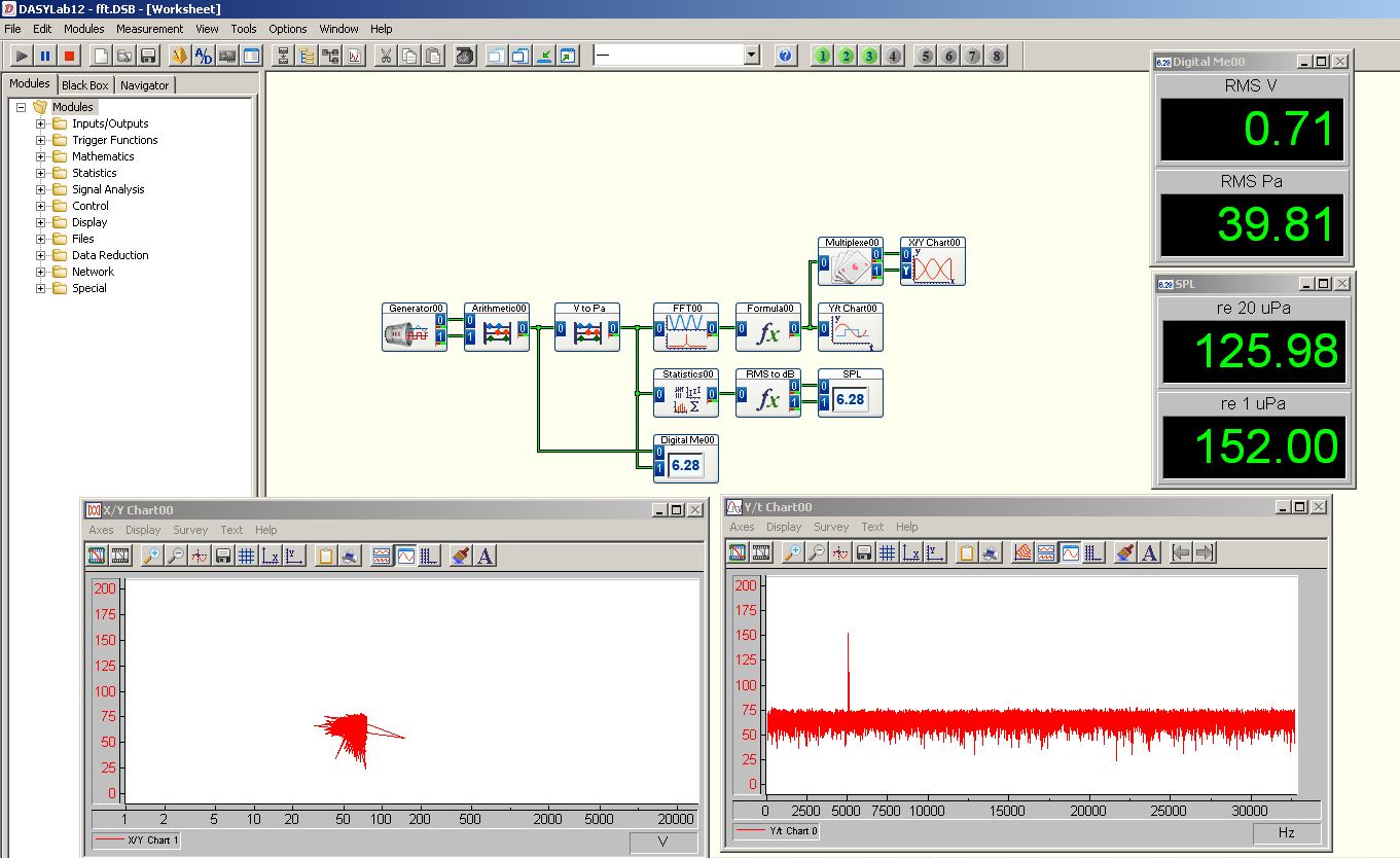
I'm looking for help in the analysis of vibrations. I use an example updated NI 9233 VI, to get a signal from the accelerometer for display using a FFT power spectrum. I'm not entirely sure if it works, because it's the first time I've ever done vibration analysis on LabView. So if you could explain a thing or two about vibrations or TFF, I'd be more than willing to hear from you. I have included my code along with a photo of an analysis of vibration of the computer, I work with. (even when I don't know if his work that I just thought it would be good to show an output)
Brandon
Data sheet:
I have LabView 2011
I FPGA, real-time
I have a model of research of Wilcoxon accelerometer 797-33
With an NI 9233
On a cRio-9012
Hi Brandon,.
You can use the FFT Complex (photo attached) to calculate the magnitude of the acceleration at different frequencies. You will need to take a little further to build a new waveform with this release, which includes d0, df and the output of the FFT. In order to calculate the df, please refer to the user manual on page 10-3. With respect to the scale that is output by the FFT, it must be same as input. Hope this helps to answer your questions. Thank you!
See you soon,.
CARISA Leal
-
FFT on several channels in FPGA
I have a client with a 9076 (Spartan-6 LX45) who wishes to perform the FFT on several channels of a module of 9205.
I never run FFT on several channels and never run out of space on the FPGA before, but I strongly suspect that this could change that. Before I start to code this and play, someone can experience with this scenario - that offer you an optimal architecture / let me know how many channels can I expect to treat?
Hey Jed,.
As someone who has done a very similar application, but with the DC/RMS measurements, I can say with confidence that Yes, this is going to change that... How many channels your client wants to do and what kind of flow? I was able to get up to 64 is going, but it took most all of the fabric, and I had to write my own calculation of DC/RMS multiplex VI. So under a flow of course (I think we had each channel was updated to 1 Hz with 1000 samples per channel). Therefore, when writing a VI that multiplexes across all channel data, you could theoretically get many channels out there, but you sacrifice a flow.
Basically, I modified the existing Express VI to store its State in BRAM between each call and he's travelled to the number of channels * samples I was doing. Not terribly difficult, but your time trying to find a good balance for the given application.
Maybe you are looking for
-
When I open firefox, it opens and after 1-2 seconds it closes so I can't do anything and it will open and close automatically several times.I have uninstall for a month of waiting for the new version hopes can solve this problem, but he cant last ver
-
Some plugins don't appear on the page of the Check Plugin on Mac
I use Firefox 35.0.1 on a MacBook OSX Yosemite running. I open the Add-ons Manager, go to the Plugins and click on 'check to see if your plugins are up to date. This brings me to the Plugin Check page. However, none of my plugins are listed on this p
-
Sometimes do not see a way to refuse an incoming call
Usually, when I get a call on my iPhone, there is a button I can type to reject the call. But sometimes I can not see this button. I just got a call and my screen displays two buttons: was remembered on the left and on the right was Message, with a
-
. When I create a shortcut to a URL, how can I make firefox use the icon of this site, rather than the icon of firefox genaric?.
-
Fan on my M30 runs often and strong
In the last 45 days, on my M30, fan works very often and very strong, no mater the ambient temperature. When I start a program, even a small one like Outlook Express or Adobe, fan starts to work very hard.Bane