Route signals to output multiple CS6
Hello! Is is possible to route the output signal to multiple output on my interface at the same time? And if so, how to set up that?
Best regards, Charles
The only way I think you can do is put in place several fade after sending each channel, one for each output you want to use. You need a bus to each separate output that you want, and then you have to allocate to each shipment of each channel to a bus each - if you see what I mean.
What you have actually done at this stage is to make the master output redundant, and each bus, with the channels that you want to use sent to her, becomes a new master. Each bus can be allocated specifically to the release of material. Well, it's a little difficult to set up, but it should work.
Tags: Audition
Similar Questions
-
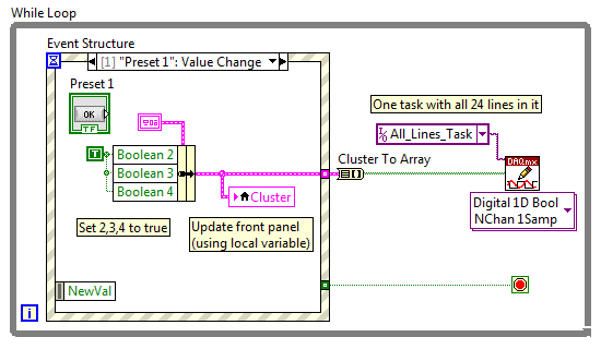
How do I turn on/off outputs multiples with a single button using USB-6501 & Labview 2010
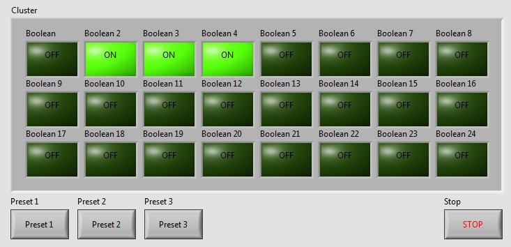
I've written a VI with 24 buttons, one for each output of the USB-6501, for turning on and off 24 relay. Now, I want to add more buttons that activate and deactivate the outputs multiple. We will call these Presets buttons and pressing the Preset button a few outings turn and some turn off. Get it? The VI I've included a screen shot is used to test a transmission controller and rather than to manually select one at a time relay I want a preset button that sets up instantly relays for the next stage of the event.
The VI I wrote uses tasks created in NI MAX.
I am a beginner of Labview, so please try to keep your easy to understand solutions if possible.
Thank you
Kevin
BTW, I'm registered in Core 1 and 2 month next to Richardson, Texas.
Here's an example - you will learn about the grapes, berries, events, etc., in the class, but this will give you a head start. Code is attached but I took a screenshot to give people an idea of how simple the schema becomes:
As your learn about them, I suggest you also make the cluster a TypeDef and make management mistakes, but I've omitted the example to keep things as simple as I could.
Good luck, LabVIEW learning, it is worth!
~ Simon
-
split the signal not showing multiple output
I'm dividing the multichannel signal from acquisition of data NOR-6008. When I connect the data to the separation of the vi signal, there is that a single output eventhough I did the dow to give me all the outputs.
Please help its urgent.
What version of LabVIEW are you using? You can post your VI?
If I remember, one of the versions of LabVIEW had a bug in how the signal split function would work.
-
Is it possible to route signals of relaxation between two chassis PXI-1002 with the PXI-8335?
Hello
as the subject says, I am interested in the delivery of a signal to trigger between two chassis PXI-1002. At present, these two chassis are connected by a MXI - 3 system using maps PXI-8335. The software is Labview 2010 sp1 and 380 NIScope drivers.
We want to keep (a PXI-5122 by chassis) scanners supply separated due to the requirements of our measure! The chassis are connected via cable to fiber optic. This explains why I can not just use the shutter release in Star, or connect via 'Trigger' or 'clk' cards (the inputs / outputs to the front of the cards).
I found a few examples, but they seem to all be designed for use with a chassis only, I'll call later to the examples that inspired me to this point. Each guide explaining the synchronization of several chassis systems seems to use another material or VI is not accesible to me. This makes me wonder if my hardware has the capacibilities I need.
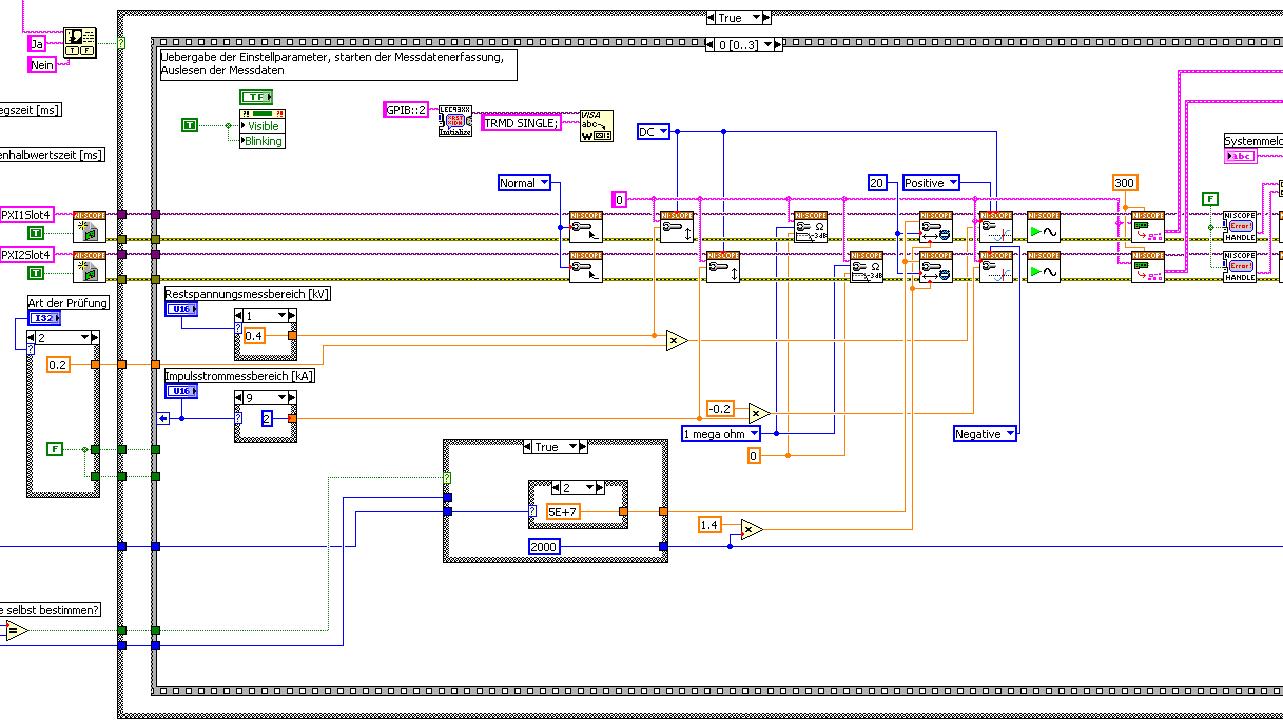
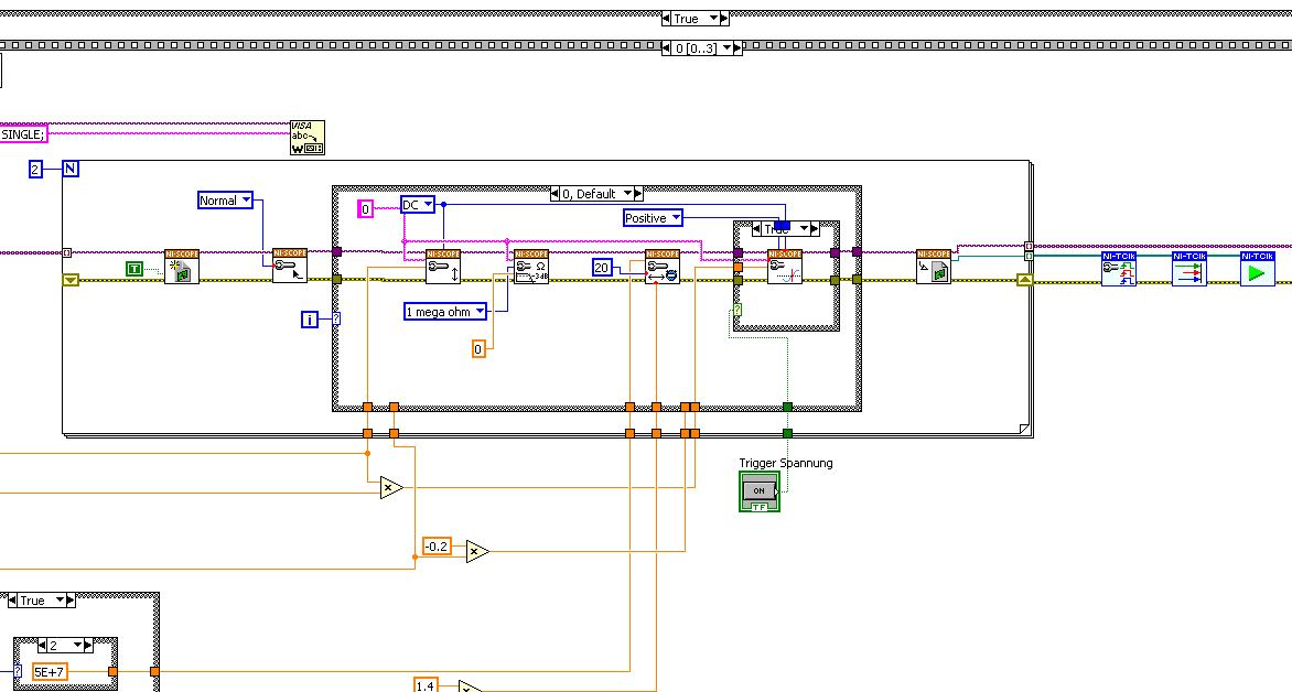
The first picture shows approximately where I started from (sorry I can't post VI, confidential...):
Only the middle part is interesting. Two sessions are initialized and manipulated parallel, trigger too. This has led to delays in the signals and should now be fixed. This apart from the VI works fine.
Goal is to trigger only on one channel but both devices! If possible, the device will trigger must be chooseable.
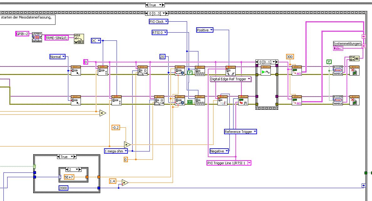
I started to rebuild the VI using the "EX Synchronization.vi 5xxx niScope' seeming spontaneity. The result is shown in the following image:
I tried different RTSI lines, but had no positive results. only the main channel has triggered.
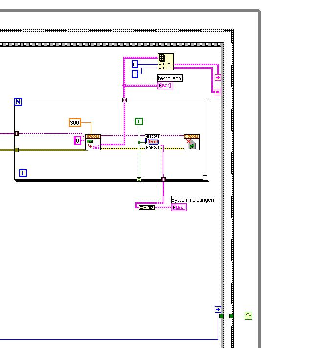
After this first approach, I looked in the "niScope EX .vi multi-Device configured Acquisition (TClk)" and other examples of TClk which seem to work for similar problems. The VI of reconstruction can be seen in the following images:
(Sorry, I had to use two photos..)
In this case, I didn't have no choice for trigger lines, it would automatically set the VI TClk. I tried to trigger on both devices, though. This second approach seemed promising to me, but it was an error:
"niTClk Synchronize.vi:1".
Index (starting at zero) of the session: 1
The error reported by the pilot of the instrument:
No registered trigger could be found between the
devices on the route.If you have a PXI chassis, the chassis correctly identify in
MAX and make sure that it has been configured correctly. If you use PCI
devices, make sure they are connected with a RTSI cable and that the cable RTSI
is saved to the MAX. Otherwise, make sure that there is an available trigger line
the trigger bus shared between devices.Source device: PXI1Slot4
Target unit: PXI2Slot4
Status code:-89125niTClk Synchronize.vi:1
Index (starting at zero) of the session: 1
The error reported by the pilot of the instrument:
No registered trigger could be found between the
devices on the route.If you have a PXI chassis, the chassis correctly identify in
MAX and make sure that it has been configured correctly. If you use PCI
devices, make sure they are connected with a RTSI cable and that the cable RTSI
is saved to the MAX. Otherwise, make sure that there is an available trigger line
the trigger bus shared between devices.Source device: PXI1Slot4
Target unit: PXI2Slot4
"Status code:-89125"
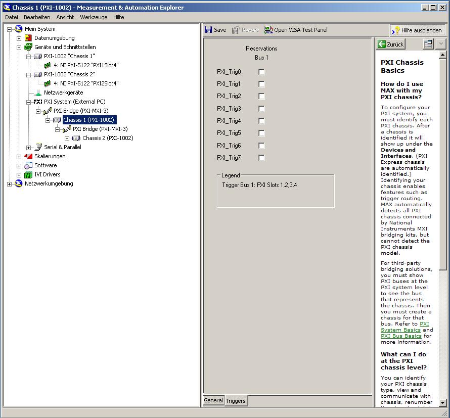
This error came back even after I've identified this drug as possible to the MAX, as shown in the screenshot:
In some of the textbooks, they showed how to get the MAX trigger lines, but as you can see, there is only booking options in my MAX. Whatever I do, I can't find options to define how to get my trigger signals...
In principle, it is possible to trigger instruments in different chassis, which is indicated in this Guide and others... the question that remains is can it be done with my set of components?
I understand that the use of multichassis compromised the integrity of the lines very adjusted as trigger in Star etc., so the configuration should be taken into account in some way, that my approach does not, I knew... But there must be a way to do this? And to start: to get just any signal from one device to the other trigger!
For any advice on this issue, I would be very thanfull!
Concerning
Max1744
Hi Max,.
Thanks for the detailed post and explanations of your application and requirements. You're right using TClk, because this is the optimal method to synchronize the 5122 digitizers. The original VI you worked with is unique for some of the legacy scanners and does not directly work with scanners based on the most recent CMS (for example the 5122). The good news is that you can synchronize these cards to separate chassis, but it will use the calendar 66xx and synchronization (T & S) cards in the chassis of the master and the slave, as indicated in the guide that you have accessed. These are needed because a common reference clock must be shared between them as well as a couple of tripping. MXI itself can not handle export triggers and clocks, so there is no way to do this without physically wiring between the chassis with cards T & S. Unfortunately, regardless of what specific method, you use for synchronization, it will take a material extra beyond what you currently have.
As one of your needs looks like it is necessary to retain wiring between the chassis directly, you may need to consider to synchronize using 1588 or GPS protocols. 1588 Protocol is a system for synchronization on the network while GPS course use antennas and locks for a common wireless signal. Although these synchronization methods may allow you to keep your chassis isolated, they will also require some manual configuration because you would be able to use the TClk synchronization and so the level of synchronization you can get between the cards may not be as good that can physically wire signals between the chassis using T & S cards.
Hope this helps,
-
NEITHER 6052e: can I re - route the analog output of DAQ for PFI?
Hello
Does anyone know if it is possible to route analog output to one of the PFI (e.g. PFI0)? I use NEITHER 6052e and I would do the following: 1) output a signal to DAQ0; 2) then a few hundred milliseconds a signal of DAQ1; and then 3) read out a simple analog pulse on any output connector external to trigger an external device.
Thank you very much for your help!
Hello sometimes.
Could you please provide more information about your hardware configuration:
What devices are DAQ0 and DAQ1?
Are you using a PXI and PCI 6052?
When you say AO reroute to PFI do you mean you're trying to wire AO into a PFI line for release purposes or are you trying to exit and the analog signal of a PFI line?
-
Is there a way to output multiple waves to the soundboard
Work on two projects that could benefit from multiple sounds played at the same time.
1 is a C64 SID emulator. The SID has 3 voices each with their own ADSR waveform. I can generate a unique waveform with the attack and degradation and decent sound out. But the mixture has been problematic. I want to have almost 3 whole running loops. Each sending signals to the soundboard. I've done this before in VB... hmm... im thinking maybe I used directx. Been awhile. Guess I could import an activex object that handles playback of sounds? Ill research on this idea. All others would be useful
2nd is a game_API. I see boring games for labview. Like the game of checkers or chess. Using an array of 2d images. He does this (reversi). So I started on a basis game_API sprites of loading and display on a photo. What I need is music and sound effects. Need to play music in the background, then break or fire play these sounds. Few in the same sense as my other project.
Question side: loading and playing of MP3 files in labview? So far, I can get the frame header... So, what are you doing? I can't find the info to decompress anywhere frame only header information. Not that important I just wanted to play music and saw that nobody did it mp3 I tried, but got stuck.
-Profit
In the event that a person is responsible for the research as if I were. Searching around for the most I found someone who has used the winmm.dll mcisendmessage to open a CD player in 2005. Using the appeal of the dll, you can also play sounds. In my attached example, I used a wav file, but I think that mp3 files should work too. Not sure if a leak memory happen with this example. As I don't know how to delete the alias, I created. Some more code to look at his process and delete the alias configuration, once the sound is done can help or will be necessary. But this example may be a person moving in the right direction.
PS im still looking for a good way to play 3 waves created in labview, at the same time. Indeed more control on the labview vi soundplay would be nice.
Edit: hmm, I took the extract from the default to open the side. The only difference is instead of close I use play to play the sound once an alias has been created.
Not part of the alias allows to play multiple sounds at once. Using only ['filename'] will lead until it ends before you can send the next sound. Alias is the key to make this work.
Edit: use labview 2011.
-
I currently have a string of the guitar signal electric-Rocksmith Real Tone cable - ASIO 4 all help IK Multimedia Amplitube 3. I would like to know if I could also watch DVD with her while the implementation of the programme of Amplitube with sound. It would be great that I use the DVD for guitar and play at the same time. I don't have the signal of two merged as one. In my mind, I should be able to disable the ASIO devices and use them with DirectX as usual. I could send the ampitube signal to the headphones and use external speakers for the guitar signal, and use the lessons of speakers for the DVD (or maybe YouTube) laptop on board.
Is this possible?
How can I do?
Toshiba Satellite X 205-S7483
Jeff
Yes. For example, I have my Skype phone calls go to my helmet (normal just plugged in the headset) while my media player plays my speakers. You can choose your default communication or multimedia devices with a right click on the volume control icon and choosing "playback devices".
Other programs can also be built to be "to the output current" and allow you to choose the output too.
-
Tunnels of router that support s multiple VPN IPsec AND SSL VPN
I have a main office and an office, each with a RVL200 connected via the IPSec VPN tunnel. We grow faster than we thought and add 2 more branches. Is there a router that is similar to the RVL200 can I put in my main office in support of multiple IPSec tunnels connected to RVL200 in branches, but also keep the SSL VPN?
It seems that the Cisco ASA 5505 will do.
-
Control button to assign outputs multiple
Hello world
So here's my situation. I should preface this by saying: I've been using logic in one form or another since before Apple bought eMagic, but I actually never knew if it was possible to do.
If any of you have used Pro Tools you probably know how defining the inputs and outputs for several tracks at once is just child's play hold down shift + Option to assign the same entry or exit to all channels (e.g. channel 1 = 1; Track 2 = 1; Track 3 = 1) and shift + Option + command to assign the outputs in the following by ascending (i.e. the way 1 = 1; Track 2 = 2; Track 3 = 3, etc...). I have become more and more fed up with the greed of Avid and total lack of support or caring what their customers want them and have decided to make my primary DAW for Logic Pro x (previously I used it mainly for sequencing) and I really want to know if this is possible in Logic Pro X because I really liked this feature in Pro Tools.
Anyone know if this is feasible in the logic?
Highlight the channel strips to define...
Select one of the output of the channel bandwidth and the value it... all others who are highlighted the same will be defined.
sequential:
same process as above except hold down the option key when you select the output...

-
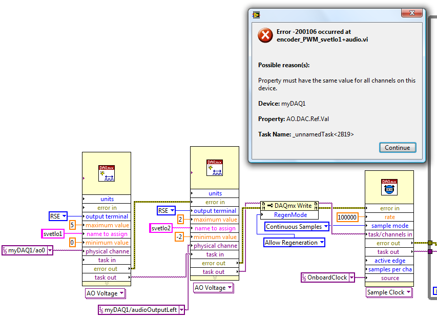
myDAQ - output multiple analog/audio
Hello
I try to use fully the potential of myDAQ - I like to use all 4 analog outputs at the same time, in a VI.
That is, 2 outputs analog (AO0 AO1) and 2 audio outputs (audioOutputLeft, audioOutputRight). Different values mini-maxi are also required, 0/5V and AO - 2/2V for audio.
I can run analog 2 or 2 audio outputs at the same time, but not all 4.
Simply add two separate DAQ help gives me error 50103 well known, add all channels in a single DAQ help error 200106 (due to different values of the min - max)
I also tested functions for data acquisition - create channels in the series, but who returns the same error 200106.
I don't need exact date, just of various waveforms on all 4 outputs would be great.
Is in any way how to proceed? Any help is an apprentice.
JakubHi Jakub,
According to the documentation of MyDAQ the following link http://www.ni.com/pdf/manuals/373060e.pdf
Page 6 it is stated the following:
-
The router RSV4000 does support multiple public IP addresses
I have a client who has a RSV4000 router. The customer also bought a block of 5 usable public IP addresses. I need to be able to assign these public IP addresses for printers, either by configuring a static IP address on each printer directly or through mapping of intellectual property or any other method. Made support for RSV4000 using several treats public IP and if so what configuration is required in the router for printers to be seen by the outside world.
Hi Winston,
Thank you for posting. The functionality you need is one-to-one NAT, who does not have the RVS4000. Please watch the RV042 or RV220W for this feature.
-
Is it save to use the digital output as a digital input for another channel signal
Hi all
I know it's a stupid question, but I don't have another generator of signals by hand. What I want to know is, can I use the signal digital output of my USB-6001 as an input for the same signal device, but on other digital port? I wasn't directly because I don't want to burn the device...
Thank you
Done all the time. No problems.
-
Computer "is" more low-signal router instead of range extender
I've seen a few similar posts; but nothing seems exactly like my problem; or I missed it.
I have a router WRT54G and WRE54G range extender; seem to be working well and talk to each other. (Took a while, but I got it; and it has been fine since.) I connected to the signal stronger WRE fast when Internet and slow Internet when WRT connected to the lower signal (which is further) - just like one would expect.
The problem: my computer (only place Office) will be unrelated to the stronger signal "Range Extender". I'll work some time or leave and come back - and the link will be back signal Extender, fast router signal slow, lower. I can click on my profile; Connect and sometimes come back on the most powerful signal. (If not, try again and again until it crashes into the most powerful signal.) [Even with "site survey" - I select Connect to the stronger signal, but it seems to connect randomly either.]
- & - Another post, I think I could do something with the MAC addresses - for example, block my USB MAC of the router wireless receiver, so he 'only' to connect to the Extender. (Better yet, I can say my network connection to connect only to the MAC of the extender?)
Operating system is - 2000
Here's something I put in place earlier - for the most part just repeats above:
Equipment:
LinkSys wireless router; WRT54G; 6 worm. Firmware 1.00.7 (now 1.02.7)
LinkSys Range Extenders; WRE54G; Firmware Ver 3 3.01.01 (now 3.04.01.)
USB LinkSys network adapter: WUSB54G Ver 4
-WHY it keep coming back to the lowest signal from router? (The big question).
-Why, when I do a site survey, select the strongest signal and select Connect, enter the WEP code, he still occasionally connect back right at the lowest signal from router, even if I've highlighted the stronger signal Repeater when I hit the Connect button?
-If I create profiles with the most powerful signal, it is always the same (that is, sometimes it connects the signal the most powerful signal "Extender" and sometimes the Repeater weaker signal, except that I do not need to enter the WEP code if I connect to the profile instead of the signal of view survey.)
-According to information online, I found that the router must be on 'Firmware version 2.02.2' to be compatible WRE; But - if I check for the latest version of the firmware for WRT54G version 6, it is 1.02.7 - does that mean the Extender is incompatible with my router?
-Are there a way to "force" the wireless network connection to bind to a specific MAC address - so I can restrict to a stronger signal of the Extender?
Scrooge, thanks for the suggestions. Earlier, I tried the following solution, based on a similar condition a few - this on another post:
Solution: Configure the router MAC filtering does not to allow connections to the MAC address of the wireless USB network card.
Since I tried this a few days ago I was followed and it worked. So, before he would keep switching to the smaller Repeater link. In saying the Repeater from the heat to let the link not only the Extender to post a link and it is now to stay connected to the Extender and the speed remains constant.
-
Pretty simple question really. I want to activate the outputs audio multiples to be active, so I don't have to wear my helmet all the time, or need to disconnect anything to the speakers. I checked the 'sound' thing in the Control Panel, but the enable option is not letting actually work. So if I want friends to hear my video games or something else, I turn on my speakers and they can hear it now.
Thank you.Windows 7, 64 bit.Audio original tittle: multiple
Windows does not support this. This is handled by the device drivers or hardware - if they don't support the outputs multiple, you can try the search for an alternative solution.
-
With the help of 2 generators of signals on a FIFO shared
I have the device of the series M (NI USB-6259) and would create 2 tasks, DO1 and DO2, using subsets of lines on Port 0. The two waveforms will be sinosoidales, that I will store on FIFO of the device. Both tasks will have different examples of two lines PFI clock (clock is 1000 times faster than the other). In addition, the sizes of waveform for two tasks will be different also.
Once the tasks are started, I want to send the waveform to MAKE FIFO data and the RegenMode set to True in order to eliminate ongoing entries of the computer to the USB/PCI bus FIFO buffer.
My question is - is the device M-series allow reading of FIFO to DO separately two DO tasks to different sample clocks?
If the answer is NO, can I disable FIFO for one or two tasks by setting UseOnlyOnBrdMem to True? Are there any device not M-series allow 2 tasks FIFOed DO?
If the answer is YES, are there settings/options on which must be paid to work? I would have preferred an example of use of Measurement Studio (DAQmx C API).Victor
Hi vicpik,
I don't know what you mean by sinosoidales referring to digital output lines, do you mean you want to produce trains of pulses with a cycle of 50%?
The 6259 allows correlated digital i/o on port 0, which means that it is hardware timed but the clock must be from another source. However, there is only a single circuit of calendar for digital output so that you cannot route signals from multiple locations on different lines. Thus, two output lines digital correlated cannot have separate examples of clock.
There is probably a way you can reach your goal with the 6259, but again, I'm not clear on what you mean by sinusoids. The standard way to write several digital lines at different rates on the same timing system would be to use the lowest common denominator for your clock frequency and generate several samples that needed to create any arbitrary digital signal. I hope that this makes sense, but please let me know if not.
The other option, if you need to generate a simple square wave or pulse train would be to use the meter exits the 6259. Additional information would be useful to determine the best course of action. Thanks for posting!
-John

Maybe you are looking for
-
The same e-mail message keeps loading over and over but no new messages arrive.
The problem is not with the provider. I have new messages on another access device.
-
Re: The Finalis A300D - 13 X has bluetooth on it?
IM reading spec who say he still can't seem to find it on the system from anywhere... I'm using Windows 7 64 bit. Any help would be fab :)
-
How can I enlarge the icons and text on my ipad Air2 home screen?
I have an iPad Air2 and I want to enlarge the icons and text on the home screen. Is this possible? iOS 9.2
-
for Internet explore 8 for Windows XP (KB2817183) is the 4/10 yet to microsoft update of the page it tells me that a highest priority update but there is: Total: 1 updates, 0 KB 0 minutes *... y at - it something wrong with the site?
-
I can't publish my movie, he will not go beyond 10%
I made a movie in movie maker and tried to publish... such attempt got the second attempt of 5% arrived at 10%, I then did a test with some of my photos, videos and audio used in the film and published, I can watch on my playstation on the TV. I have