Scan of arrears in DAQmx
In the 'rear' traditional DAQ used to scan Read.VI as output. However, the DAQmx Read.VI does one. The value is crucial in my program, it really need. Can someone tell me how to get new DAQmx?
Thanks in advance.
Best,
Jay
Hello jeongho20000,
The property node you are looking for specifically is a node of DAQmx Read property. The property is shown below. One thing you should be aware of good is available per channel samples will return 0 if you have already overflowed your buffer. I hope this helps!

Tags: NI Software
Similar Questions
-
Hello
I am trying to create a LabVIEW program that controls two bipolar motors to create a raster scan. I use DAQmx and Labview 2012 SP1 with a usb 6008. I got the engines to move in one direction, but when I try and get them to move in another direction in a separate task, I get an error-200088 code indicating that my task is not valid. This happens at the beginning vi to move the motor x in the opposite direction of the task.
The logic underlying the program is as follows:
1. move the engine x a certain number of steps to the right
2. move the engine are a number of steps down
3. move the engine x the same number of steps as 1 to the left
4. get off the engine is the same number of steps 2
5. repeat
I can get the steps 1 and 2 work but I have problems with step 3. I use a stacked sequence to show the task for each step.
I appricate all the advice on this topic as part of a final year project
Thank you
Aoife
You can solve this problem very simply. Move all DAQmx departure calls happen * before * the structure of sequence rather than inside. Similarly,.
move all calls to DAQmx Stop and DAQmx Clear happen * after * the structure of sequence rather than inside.
I would sequence the DAQmx Write calls to write the bit of direction * before * writing the bit clock. And I highly recommend that wire you
to the top of your tenants error and outs so you can be informed of any errors in the DAQmx tasks.
-Kevin P
-
How to synchronize the start of IT and relaxation the Scan list (DAQmx Switch)
Hello
I want to measure samples of N to the AI0 of Council NI PXI 4461. The measurement starts on a rising edge of a digital triggering provided to the PFI0 of the same Board. The measure is configured with samples of N/2 pretrigged. So far, everything is under control...
Using an NI PXI 2567 Board, the signal applied at the entrance the 4461 (AI0) switches between a V2 and V1 signal. I would like to synchronize the switch between the two signals with the trigger signal applied to the input of the PFI0 Governing Council 4461. In order to obtain samples of N/2 of V1 and V2 samples N/2. Synchronization of 1 to 5 ms would suffice!
My question is how to synchronize the start of acquisition of AI pretrigged of 4461 with the switch control given by the Council of 2567?
Thank you in advance for your help...
PS: the configuration of the system is:
-LabView 8.5
-Chassis PXI-1044
PXI-4461 on slot 2
Module 4-slot PXI-2567
Hi Frederic,.
I came back to this recently and used the following examples to run the desired synchronization.
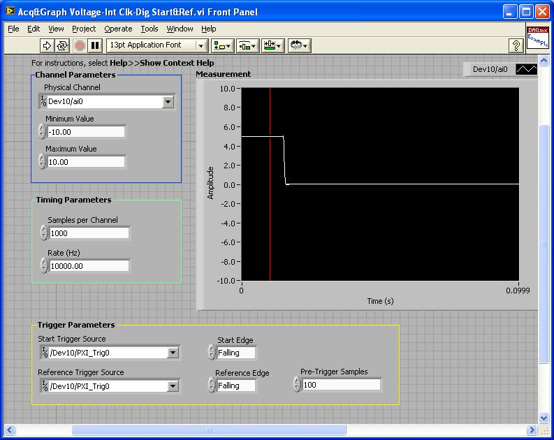
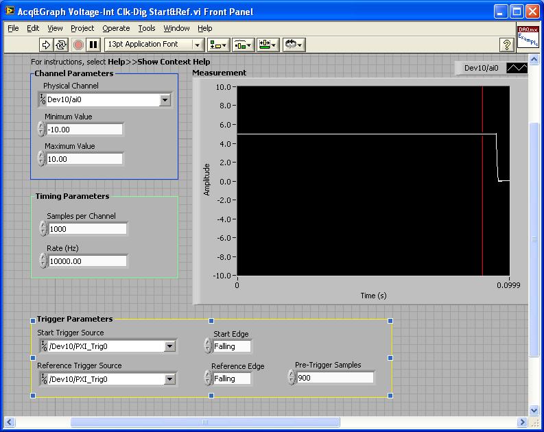
PXI-4461: Acq & graph tension-Int Clk - dig Start & Ref .vi
Samples per channel = 1000
Rate (Hz) = 10000.00
Start the trigger Source = / [name of the instrument DAQmx] / PXI_Trig0
Onboard start = fall
Reference Source Trigger = DAQmx Device Name] / PXI_Trig0
Reference edge = fall
Trigger samples = Variable (100, 500, 900)
PXI-2567: Switch Scaning-SW Trigger.vi
Advance the output terminal full = / [name of the instrument DAQmx] / PXI_Trig0
Scan list = / [name of the instrument DAQmx] / ch0-> com0.
Scan list = / [name of the instrument DAQmx] / ch1-> com1;
Hardware configuration:
The PXI-2567 module controls an external relay that switches between the voltage of 5 V on ch0 and ch1 0 V.
The PXI-4461 connects to the COM of the external relay and therefore reads 5V when ch0 is connected; 0 v when ch1 is connected.
Procedure: The above examples are used in the following procedure.
1. run the PXI-4461 VI. A start trigger (falling edge) is necessary to start collecting samples before firing.
2. launch the module, PXI - 2567 VI. When ch0 is initially (and immediately) on com0, a trigger is sent to PXI_Trig0. The PXI-4461 will begin to acquire samples before firing.
3. - click on the "Connect to the next" button on the front of the PXI - 2567 VI module. This sends a trigger to entry software for the PXI-2567 module and the transitions of the scan for ch1-> com1 list. Once the PXI-2567 module remains (debounced), advanced complete relaxation is sent on PXI_Trig0 for the PXI-4461. The PXI-4461 will begin to acquire samples after outbreak.
Note: Instead of the trigger of the software entry, an external input trigger can be used (e.g. PXI_Trig1).
Results:
> Before instant release of samples = 100
Delay is caused by the time of actuation of external relay.
> Before instant release of samples = 500
Delay is caused by the time of actuation of external relay.
> Before instant release of samples = 900
Delay is caused by the time of actuation of external relay.
I hope that the attached screws and the explanation above helps you and/or other customers who have this problem.
Best regards
Chad Erickson
Switch Product Support Engineer
NOR - USA
-
Can I use ' I read a Scan VI "daq and driver DAQmx Labview 7.1 with a new card?
I need to use old software in which the data is to use ' I read a Scan VI.
I think that with labview 7.1.
now, I work with Labview 8.5 and the new daq card that I want to use comes with NOR-DAQmx.
is there a compatibility problem between these two.
Please clear my doubts.
Thanks in advance
Renn
It is used with 8.5 cards and as long as you install the driver traditional. It should be on your LabVIEW CD or download it from here. New cards require DAQmx and you need to rewrite your code.
-
Repeat the Scans with DAQmx read/write
Hello:
I use DAQmx vi to generate signals on channels ao0/1 a reading of the signals of the channels ai0/1 a card NI USB DAQ of 6251. I do this by using the read and write of vi and a trigger vi. This vi will run successfully for a single analysis. Now, I need to be able to perform multiple scans with the same settings but separated by 5 seconds or more. When I click on Scan, the vi analysis. However, when I click scan again once it does nothing and I don't know how to scan again.
The vi VU RAMP MOD (not included) is simply used to generate the shape of the signal.
Thank you!
-
How to control the sequence of scanning channels in DAQmx
I have an application written for the traditional DAQ C API that I need to convert to use DAQmx drivers. The application uses the SCAN_Setup function to create a canal complex analysis sequence of taste effectively at different rates on each channel and to vary the rate on one of these channels. The following example shows the sequence of sweeping strings passed as an argument to the call of SCAN_Setup chanVector:
0 0 0 0 0 0 0 0 0 0 0 1 0 2 0 3 0 1 0 2 0 3 0 1 0 2 0 3
The sequence of I is synchronized with a waveform of the AO and is designed to measure response on AI0 from an external system to this waveform while taking other measures from other sensors at the same time: AI1, 2 and 3. This sequence provides a higher AI0 at the beginning of the wave sample rate.
How can I do this using DAQmx?
I tried to use a loop to make several calls to the DAQmxCreateAIVoltageChan function, one for each sample in the vector of channel, but the result does not seem to read the right channels in the correct order.
Is there a problem with the addition of several times the same physical channel in the same task?
Thanks for your help.
Hi TradLuddite,
Material of the series E have a specification 'size of the memory configuration' of '512 words', which means that they can sweep up to 512 unique physical channels. I would wait until a depth of 1000 causes the DAQmxStartTask() return an error. However, it may be possible to exceed this limit, if the scanlist consists only of the groups of the same size of the identical physical channels (where the entry terminal configuration limits are the same within each group), because the material is supported by a very simple form of compression scanlist. Material of the series M have a specification corresponding loads "scan memory list" 'entries of 4095', to a depth of 1000 would not be in this limitation on the M series.
Definition of the data property of transfer mechanism is probably not necessary. DAQmx chooses a default value for this property, depending on the type of device and the type of calendar sample property. The use of DAQmxCfgSampClkTiming() to set the calendar type of sample to "Sample clock" will result in a mechanism for transfer of data by default "DMA", "USB in bulk" or "Pauses" depending on the type of bus (PCI/PXI, USB and PC Card, respectively). Not configuration synchronization (or by calling DAQmxSetSampTimingType (taskHandle, DAQmx_Val_OnDemand)) will result in a mechanism for transfer of data by default "set of I/o.
What DAQmxRead() function are you? You specify DAQmx_Val_GroupByChannel or DAQmx_Val_GroupByScanNumber for the fillMode parameter? Have you checked the value returned in * sampsPerChanRead?
Only repeated channels return incorrect data? It works when you repeat all the channels? Otherwise, maybe the terminalConfig parameter does not correspond to how signals are wired, you have ghosting, or there is a problem with the wiring for signals. It still works in NOR-traditional DAQ?
Brad
-
Continuous sampling PlotStripChart DAQmx and multiple channels
I modified the sample code sychAI DAQmx - AO.cws slightly to provide more output wavforms. I can read at the same time on a single channel without problem. Then when I try two channels I read in an array of N (N > have a lot of examples of PlotStripChart 2, N = 2 with 2 tracks so it updates a point at a time...) I don't want that.) samples. 0 to N - 1/2 is what AO1 (output channel 1) written on, and N/2 to N - 1, that's what written AO2. Now, if I put the number of tracks 2 and try to draw on a stripchart I get the range 0 to N - 1 on both routes.
How to draw a picture of say 10000 samples on 2 tracks with table grouped by channel?
Thank you
I changed my DAQmxReadF64 to the group by number of Scan instead of channel and set skipcount = 0 and staringIndex = 0 and which has worked exactly as I wanted... but according to documentation it should not work.
-
Handshaking DMM with multiple switching devices - DAQmx error
Hello.
I am trying to create a loop of the handshake with DMM (PXI-4071), SWITCH (PXI-2569) and MUX (PXI-2575). The three instruments are in segment 2 chassis PXI-1045 (locations, 8, 9 and 10) and I use the ways of PXI trigger in the triggers of the route.
I followed the article NOR 'Multimodule Scanning with National Instruments switches' - I modified the example NI SWITCH "niSwitchDMMSwitchHandshaking" to set up another SWITCH, but when I tried to run the example, I got an error:
0xbffa6b9a - no lines recorded could be found between the device in the road. (screenshot pop up is in the attachment). It is the function of niSwitch_InitiateScan to the second switch that returned an error.PIX trigger change has no effect.
I tried the CVI and LabVIEW examples with the same result.
I even tried to use two 2575 MUXes - same result.Can someone tell me what I am doing wrong?
Hi Pavel,
I checked that the component that controls the routing of the TTL for the PXI is included in NOR-DMM 3.0.2 (latest version as of 06/14/2010). NOR-DMM 3.0.1 contains an older version of the TTL routing code and will therefore place several comprehensive lines scanning advanced on the same trigger.
Unfortunately, the component which controls TTL routing is one of the constituent elements of the software installed OR lower, and thus we do not expose it to the user. For that to work, we would need to uninstall almost all the software components of NOR, which is a major undertaking. Here's what I recommend instead:
For now, we will Garland triggers one switch to another. This will allow us to start development in OR-Switch; as soon as OR distributes a program, you simply change the triggers as they all point to the same TTL line. This will allow switches to operate in parallel rather than in series, and the passage of the switch of your project can run faster.
If we have to absolutely exploit the switches at the same time, I would recommend either uninstall all software of OR or get a machine with a fresh install of XP and then install not newer than 8.9.5, OR DMM 3.0.1 DAQmx software and NI - Switch3.8.
As I mentioned earlier, NEITHER is aware of breaking backward compatibility and we are committed to reintroduce the old features in a future release of the pilot.
Keep this thread bookmark and post back in a month or two and I'll let you know if we have any updates.
Have a great day!
-
Outputs digital synchronized DAQmx
Hey, I am trying to send two synchronized digital signals of a PCIe-6420 device.
Here is my code:
DAQmx configure clock
DAQmxErrChk (DAQmxCreateTask ("Clk", & taskHandleFRQ));
DAQmxErrChk (DAQmxCreateCOPulseChanFreq(taskHandleFRQ,"Dev1/freqout","",DAQmx_Val_Hz,DAQmx_Val_Low,0,ManchSampClkFreq,0.5));DAQmx digital output configuration
DAQmxErrChk (DAQmxCreateTask ("Harmony", & taskHandleHarmony));
DAQmxErrChk (DAQmxCreateDOChan(taskHandleHarmony,channel2,"",DAQmx_Val_ChanPerLine));
DAQmxErrChk (DAQmxCfgSampClkTiming(taskHandleHarmony,"/Dev1/PFI14",ManchSampClkFreq,DAQmx_Val_Rising,DAQmx_Val_ContSamps,sendCount));DAQmxErrChk (DAQmxCreateTask ("DOchan", & taskHandle));
DAQmxErrChk (DAQmxCreateDOChan(taskHandle,channel,"",DAQmx_Val_ChanPerLine));
DAQmxErrChk (DAQmxCfgSampClkTiming(taskHandle,"/Dev1/PFI14",ManchSampClkFreq,DAQmx_Val_Rising,DAQmx_Val_ContSamps,sendCount));DAQmx Configure similar output
DAQmxErrChk (DAQmxCreateTask ("AOchan", & taskHandle));
DAQmxErrChk (DAQmxCreateAOVoltageChan(taskHandle,channel,"",0.0,10.0,DAQmx_Val_Volts,));
DAQmxErrChk (DAQmxCfgSampClkTiming(taskHandle,"/Dev1/PFI14",ManchSampClkFreq,DAQmx_Val_Rising,DAQmx_Val_ContSamps,sendCount));DAQmx write code
DAQmxErrChk (DAQmxWriteDigitalLines(taskHandleHarmony,sendCount,0,10,DAQmx_Val_GroupByChannel,SendManchHarmony,,));
DAQmxErrChk (DAQmxWriteDigitalLines(taskHandle,sendCount,0,10,DAQmx_Val_GroupByChannel,SendManchData,,));
DAQmxErrChk (DAQmxWriteAnalogF64(taskHandle,sendCount,0,10.0,DAQmx_Val_GroupByChannel,SendManchAnalog,,));Starting code DAQmx
DAQmxErrChk (DAQmxStartTask (taskHandleHarmony));
DAQmxErrChk (DAQmxStartTask (taskHandleFRQ));
DAQmxErrChk (DAQmxStartTask (taskHandle));Only problem, is that I get "error DAQmx: NI service platform: the specified resource is reserved." messages.
The name of the task associated with the error is DOchan: aka: taskHandle. If I rearrange the code such as taskHandler events occure before the equivelents to taskHandlerHarmony, then errors are associated with harmony: aka taskHandleHarmony instead.
That I am I doing wrong and how should outputs digital syncornized be implimented instead?
Think of the fifo in a block of memory that is the same width as the digital port where each bit corresponds to a single digital line. The samples are transferred from this FIFO to the port in written all over port (there is some logical activation, so only those lines that are configured in your output task are actually updated each sample clock). DAQmx will combine the data you write for if make sure that the correct data at the scale of the port gets written in the FIFO. DAQmx for this by looking at the configuration of the group 'line' in DAQmx create DO canal and the "dataLayout" specified for the function DAQmxWriteDigitalLines.
You have two lines you have set on DAQmx_Val_ChanPerLine. This means that when you call DAQmxWriteDigitalLines, it will be expected to see enough data to two data channels. The way in which these data are specified is configured by the dataLayout. By specifying DAQmx_Val_GroupByChannel, you say DAQmx data for each channel to be grouped. You should do these groupings in the same order that you specify your channels.
So consider the following:
DAQmxErrChk (DAQmxCreateTask ("DOTask", & taskHandleDOTask));
DAQmxErrChk (DAQmxCreateDOChan (taskHandleDOTask, "Dev1/port0/$line0", "", DAQmx_Val_ChanPerLine));
DAQmxErrChk (DAQmxCreateDOChan (taskHandleDOTask, "line1/port0/Dev1", "", DAQmx_Val_ChanPerLine));
DAQmxErrChk (DAQmxCfgSampClkTiming(taskHandleDOTask,"/Dev1/PFI14",ManchSampClkFreq,DAQmx_Val_Rising,DAQmx_Val_ContSamps,sendCount));We will alternate digital high/low between our two lines (we will write the 10 values of each line), with the exception of this last point, where we will write two lines high
The data should be written in the corresponding line bit position (if I remember correctly)which means you want to manipulate the lsb for the 0 line, and line 1 manipulate you the 2nd lsb.
Int32 [10] line0Data = {1,0,1,0,1,0,1,0,1,1}
Int32 [10] line1Data = {0,2,0,2,0,2,0,2,0,2}
Int32 dataArrayByChannel [20];
Int32 dataArrayInterleaved [20];
for (int32 i = 0; i)< 10;="">
{
Group data through
dataArrayByChannel [i] = line0Data [i];
dataArrayByChanne [i + 10] = line1Data [i];
Group the data by scanning
dataArrayInterleaved [i * 2] = line0Data [i];
dataArrayInterleaved [i * 2 + 1] = line1Data [i];
}
We can write data in one of the formats that we just built, but we must provide DAQmx with the correct dataLayout.
DAQmxErrChk (DAQmxWriteDigitalU32 (taskHandleDOTask, sendCount, 0, 10, DAQmx_Val_GroupByScanNumber, dataArrayInterleaved, NULL, NULL));
Alternatively, we could write per channel. If we chose, it would look like this (you wouldn't do both).
DAQmxErrChk (DAQmxWriteDigitalU32 (taskHandleDOTask, sendCount, 0, 10, DAQmx_Val_GroupByChannel, dataArrayByChannel, NULL, NULL));
DAQmxErrChk (DAQmxStartTask (taskHandleDOTask));
In both cases, DAQmx must write the following data to the FIFO:
x 1
x 2
x 1
x 2
x 1
x 2
x 1
x 2
x 1
x 3
In this way, the data written to each line are combined by DAQmx then written to the FIFO. Allows you to specify the data for each channel individually.
It was quite long, but I hope it will answer your question. If I was not clear, please let me know.
Dan
-
Change the frequency AO AO DC voltage scanning scan?
Hi all
I am very new to labview, but find the forums and examples extremely helpful. I probably spend 50 + hours to familiarize myself with tutorials and general information, but I am at a point where I need your help.
I'm unable to change the example "AO frequency sweep" found here (see custom_sweep_1.VI) to allow me to sweep the voltage. My instinct is that I don't need of the ' waveform buffer generation VI ' and that I should be able to remove the associated entries since I'm only interested in a sweep of DC voltage. It is also called create_log_frequencies.VI, and I'm fairly certain that I can use it as written and simply change "frequency", "tension". My work of the custom_sweep_1 changes are attached as custom_sweep_Voltage.
The problems I am having with the edition of custom_sweep_1 are:
(1) I don't think I understand very well how or if the parameters associated with waveform buffer generation VI relate to a sweep of DC voltage.
(2) an extension of 1): the loop depends on the samples and Cycles by buffer and I don't know how / whether to replace these values
(3) the .VI DAQmx Timing (sample clock) receives its sampling frequency of output waveform buffer generation VI, but I think I can use 1/scan time to replace this (?)
(4) the DAQmx Write.VI gets waveform buffer generation data, but if I can get around this VI and AO tension of wire directly to write DAQmx then I think I can use minimum voltage as my entry of data (?)
(5) after the implementation of these changes, the custom_sweep_Voltage runs, but I get error 200609:
"The possible reasons:
Generation cannot be started because the size of the selected buffer is too small.
Increase the size of the buffer.
Choose the size of the buffer: 1
Minimum required buffer size: 2"Task name: _unnamedTask<3A>"
I also note that I tried other ways to create the sweep of voltage DC VI:
(1) I have tried change the tracer IV example (found here), but it's much more confused than change the frequency sweep.
( This tutorial and sample 2) block diagram looks like straighforward, and I also work on understanding what Assistants DAQ 1,2, 3.
Any return would be great. I think it is clear that at the very least, my poor understanding of 'buffer' is if the cause of my confusion about the change of frequency scan, please do not hesitate to share any information you have.
Thank you very much for the help,
-Esperanza
Additional information on my project/progress using labview follows below:
My final goal is to determine whether or not the resistivity of a sample of organic driver changes over time. For this I want to compose a VI simultaneously sweeping the output voltage DC-5 to 5V periodically during 24 hours and measure the voltage drops to my load resistance (to determine the current in the circuit) and the sample. I use a USB 6259 DAQmx and that you have correctly configured my circuit. I work two screws that I created with the DAQ assistant and by changing some of the examples, I found online. Output voltage (of an AO) but I have to manually select the voltage value. The second reads voltages in three samples of interest and writes the data to a PDM file. If you've read this extreme sensation and still make a contribution, my next goal after finding how to sweep the voltage is to combine this with my VI measure VI. I think it will be relatively simple, but still, I rejoice in all your comments!
I solved this problem. I have changed my approach to be similar to the last link in my post. AO frequency scan approach is much more complicated that I need. Thanks for the help.
-Esperanza
-
HAVE Start.vi - number of buffers to acquire - equivalent in NOR-DAQmx
Hello
I'm trying to convert a VI above NOR-DQA traditional to NOR-DAQmx. I'm unable to find the equivalent of some inputs to the AI Start.vi
number of scans to acquire
number of buffers to acquire
Also it HAVE buffer Read.vi which is equivalent to the
time limit
I would be grateful for any guidance.
Thank you in advance.
He mailed examples for DAQmx Analog Input tasks in LabVIEW.
In the toolbar, go to:
Help > find examples (this will open the Finder of example of OR).
Select:
Material input and output > DAQmx > input analog (then select the type of task you did.)
-
niSwitch_ConfigureScanTrigger function equivalent in DAQmx
Ensuring the NOR-DAQmx library function is the function niSwitch_ConfigureScanTrigger OR-SWITCH?
I forgot to mention that I write a program in LabWindows. The proposed function named DAQmxSwitchCreateScanList has a similar behavior as niSwitch_ConfigureScanTrigger OR-SWITCH. It only creates a task with the specified list and does not allow to set the location where an advanced scan signal is generated after that an entry in the scan list is complete. I looked for a few hours and I found the DAQmxExportSignal function that performs this action in DAQmx when its second parameter is DAQmx_Val_AdvCmpltEvent.
After all, thank you for your quick response to my post.
Best regards
Miroslaw Koziol
-
DAQmx task Read DAQmx with sampling frequency of 10 Hz produced much too much data
I have a simple configuration with a strain of channel 4 OR-9237 amp holds a carrier of series C of WLS - 9163 (wired ethernet mode) - Details probably does not matter.
I used MAX to create a DAQmx task associated with which all four gauges samples. The calendar setting is "Scan Loads" is continuous sampling, 2 k buffer (read samples) and 10 Hz rate. I guess that this task would generate 40 data values per second - 10 for each channel.
I have a simple loop of reading using DAQmx Read.vi that works always (without any stimulation time). Playback is set to read all available data and then pump it into a table.
In the attached example, I also added a few words of debugging to stop the loop after N iterations.As the loop is programmed with a 0.2 second period, I expect each pass of the loop to read about 8 samples or 2 samples per sensor. Instead, I get hundreds each passage. It's like reading has substituted the sampling frequency specified in the task of the unit. I absolutely need data to be material to the rhythm.
Where have I lost?
Thanks Adnan,
I changed your example I selected 'Strain gage' entry analog and then lowered the minimum and maximum thresholds to +-1-2. What happens is that each other in the loop, I 2048 samples or zero samples. The display flashes a whole line and then it clears any other past.
In response to your second post, I understand that the loop cannot run quite right that I select. I think that, but at a sampling frequency of 10 Hz, I have to sleep on the software side for nearly a minute before I built 2 K samples.
I played with the frequency of sampling, assigning to various values from 0.1 to 10000Hz. The behavior is the same until I approach the high rates where available samples remains to 2048-4096 sometimes, the display becomes continuous.
Ahhh, Darn. Yet another search was this link that points to the root of my confusion. The 9237 can taste arbitrary rates using its internal clock. Duoh! I wish that the pilots are smart enough to warn you if there is a discrepancy between the selected sampling rate and capabilities of the device
-
I'm working on a data acquisition system for my company and we are currently running on a problem with the DAQmx code. The program follows the following general algorithm:
1. the value digital outputs control material
2. read 32 inputs analog using traditional DAQ
3. read 32 for thermocouple with DAQmx (we are using this because recent material will not support ACQUISITION OF DATA trans.)
4. processing of data, look for entries user and other functions of the program.
5. loop at 1 unless the user has ordered the program to exit.
I'm trying to let him run as fast as possible so that we can acquire data at a reasonable rate, and my goal is to get the loop to take less than 10ms. The problem I encounter is that I'm getting error-200279 of thermocouple DAQmx code. As I understand it, this means that I read in the buffer zone that is slower that data are put into the buffer, and the data that I'm reading are getting crushed. This is not a problem with the acquisition of data analog, since we put in place the traditional DAQ to buffer any. When the loop is at setp 2 it draws just in all that is on the analog channels at the moment. Thermocouples will read, but will not make it to a uniform rate. All the secondes.25 or the time to complete a loop jump of 8ms ~ to ~ 80ms, and I'm pretty sure that the problem is with the DAQmx code.
My question: what is the easiest way to get DAQmx to behave like a single traditional DAQ scan? I don't want / need an acquisition in the buffer, and I'm only using DAQmx because I can't get DAQ traditional to work with my new thermocouple material. What I would like is to configure DAQmx so it will just read the current from the thermocouple data (whatever it is) whenever the program gets in step 3. If I can do it without the loop of the program beyond 10ms by trolling line, it'll be great.
Any help on this is appreciated.
-
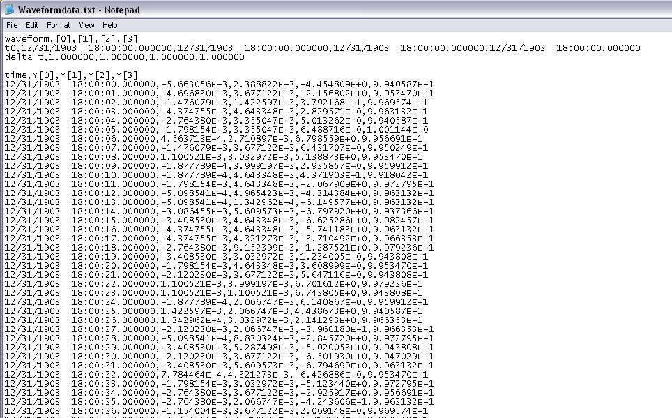
Timestamp problem DAQmx waveform
I have a program that reads analog signals multiple DAQmx using a PFI trigger from a DIO card to start the acquisition. It uses a registry to offset and Boolean logic to stop the DAQmx read the loop when the trigger is low. I traced the result to a curve of waveform. I have a 1000 S/s scanning speed. I traced the data to a graph of waveform and eye on the individual data points and it is perfect. Exactly 1 S/s. The problem: when I increase my 5000 S/s scan rate... I see exactly 1 S/s, but the displayed duration of my test data is 5 x more time. That tells me that my graph of the waveform is plotted in fact each data point individual 1ms apart. So basically, there a 1ms all dt in the waveform, and it does not change. How can I get the real dt of the analysis of data here instead of this arbitrary constant? When I look at a text of my waveform data file, I see the timestamp below where I'm expecting something ending like that... 0,0010, 0,0017, 0.0025, etc.. Any help would be appreciated. I'll post the VI if necessary, but other than the trigger power, is a fairly straightforward HERE DAQms read. Thank you in advance.
The time of LV start date is January 1, 1904 midnight GMT. Since your shows up to 6 hours before that, he must be GMT - 6. My horodateurs base are 19:00 31/12/1903, which is GMT - 5. Eastern time zone.
Are you any error coming out after your Subvi waveforms?
You empty an array of waveform data to add. The default waveform has a T0 zero and a detachment of the 1. In the Sub - VI of waveform append inside your Subvi if dt' it does not raise an error, (in fact a caveat being the 1802 error code is positive.). But she proceeds to add data and use the dt and T0 the first waveform which is initially as the default data in the initial iteration. I think that if you start with an array of wavefrom that has the number of channels of the need, an empty array of Y, but a correct dt. Then the dt should be correct. That, or you can put in your Subvi a case structure where the first call, or if the incoming waveform is empty, it is not add and uses only the 2nd waveform.
You have also a little a Rube Goldberg enters your Subvi. It could be simplified as shown in the picture as an attachment.

Maybe you are looking for
-
iTunes: unable to read smart playlist in Windows 10
I use iTunes, 10 64-bit Windows. iTunes Version: 12.4.3.1 I created a smart playlist that has 240 songs in. When I tried to play the smart playlist, using all available options to play the playlist, it is unable to play. Nothing happens. No error
-
How can I schedule a daily task that accesses a web page?
I want to access the following web page every day. http://acbldistrict22.com/534/daily.php?userid=userid & PW = Password How can I automate this in WIN7?
-
Skype id as identification of email
Hello I still have a connection with my email ID. I am not able to trace what is my exact Skype id is. Can someone help me find my exact Skype id. Please, I beg you.
-
I need to buy a cable to install an SSD in my Envy 17-j029nr. HP ENVY 17 Notebook PC Product: E0K90UA #ABA Warranty: 2y2y0y Model: 17-j029nr Rev: 1968-100 Issues related to the: What is the part number? Where can I buy it? Y at - it one provider othe
-
HP Pavilion g7 - 2250ev Notebook: Bluetooth is gone/unplugged
Nice day For about a month now, both my bluetooth devices and drivers disappeard from my laptop. I managed to install the drivers through your website (software Bluetooth Ralink driver) although I don't know if it's the right driver and now I can see