scb68 acquisition of temperature
Hello
I am trying to make the acquisition of the temperature with a 6062E and a SCB68. Do you know how the wiring of thermocouple?
How can I reffer to each channel (assuming that the 2 different threads of TC need AI 2 screws in the SCB68)? Who should be positive and negative that?
And finally, is there a way to access the reading of CCM? (it's less important to me, just for additional info)
Thank you.
Hi user,.
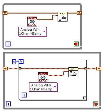
fisrt of all, you must decide closed mode the differential or distinguished as the wiring is concerned:
http://zone.NI.com/DevZone/CDA/tut/p/ID/3344
Differential > HAVE negative and positive (n) HAVE (n + 8)
CSR > HAVE AI GND negative and positive (n)
For example, the mode differential channel 0 > pin Positive AI (0) 68 and HAVE negative (8) pin 34.
If you intend to use this mode of CSR, read this document:
http://digital.NI.com/public.nsf/allkb/FADEF80B5991F4AB86256FAA006E15EF?OpenDocument
With respect to the signals from thermocouples, see this.
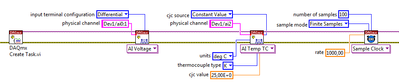
To access the value of the CCM, you must use a property node as shown in the attached screenshot.
Hope this helps! Saludos.
Jesus
Tags: NI Software
Similar Questions
-
Acquisition of temperature on USB-Temp
Hello
I use a measurement computing USB-Temp in order to acquire the temperature with several sensors. I made the attached program for both sensors. The problem is: I must add I have a waveform for each sensor. Thus, the program will become quickly unreadable if I want seven or eight sensors.
You know a way to fix? Perhaps with arrays...
Sorry for the bad English
Yes - instead of having a single waveform on your shift register, change this in a table of waveforms. You can then have your acquisition of data in a loop For the number of sensors you have.
Here's a very simple example of how you can change your program:
In addition, you should know because you generate a waveform, permanently if you run your program for a long time you will eventually run out of memory. You might want to consider looking at the architecture of producer/consumer so that your registration occurs while the data are acquired, instead of just at the end (it also means that you have given if your computer breaks down
 ).
). -
Second DAQ assistant in the power control system does not
Hi all
I need your help on this issue. I'm currently programming a VI for one command power supply for pool boiling experiments. The organizational structure of the VI program is attached.
I use two assistants DAQ for steady-state acquisition and temperature unstable state data respectively. The first assistant DAQ (samples to read 5, 5 Hz rate) for the acquisition of works unstable state data well (see the attached image file first DAQ Assistant for acquisition of temperature unstable state). The second assistant DAQ (samples to read 12 k, 200 rate) for stationary data acquisition does not work (please see attachment image Second Assistant DAQ of steady-state temperature acquisition), showing only a series of data files size of 1 KB with no data on the inside. And indicators for steady-state data also revealed nothing.
After a similar Q & A search in the forum, I tried to distribute different channels for 1 and DAQ assistant 2. However, the situation was almost the same.
The material I used are chassis SCXI 1000 and SCXI 1303 Council to acquire thermal couple temperature data. Food was AMREL SPS200-50-K025. LabVIEW software is the 2014 version.
I had just started to learn LabVIEW for only a month, and I know that the VI is a little messy. Hope you guys can also give me some advice on how to improve this VI.
Have you looked at the error on the second daq assistant? You will see that a reserved resource error because you cannot use two different assistants. You do not mention the real DAQ hardware but there a clock unique convert. You can use only one assistant with a unique sampling frequency.
-
compariing of data between iterations of the loop
I am data acquisition of temperature with a Thermocouple NI 9213 drive and DAQ Assistant in a while loop. I need to compare the temperature of a channel in an iteration of the loop with the temperature of the same string in the previous iteration. The data collected in each iteration are delivered to a chart and a data storage file. I know how to get the temperature from the data table in the current iteration, but don't know how to get the temperature of the previous iteration, except perhaps by reading the entire file in a table, determining the size of the table and query the last entries. This seems a bit ridiculous for each iteration of the loop and perhaps even embarrassing. Any suggestions?
Put the data in a record time difference. The left terminal of the shift register will have the data of the previous iteration.
Lynn
-
How to read data from the unit to acquire data with LabVIEW
Hello everyone, I'm new with LabVIEW and I need help. How to build LabVIEW program to read and store the data acquisition unit temperature data. the data can be any store such as Excel or a text file? Thank you.
Start passing by examples of LabVIEW. Go to help-> find examples. There are several examples here just for the analog input and then even more for logging data to a file. After that, show us what you have and we can guide you a little better that way.
-
Linear adjustment does not not with NaN
Hi guys.
I try to use that a good linear in fact the best solution for the acquisition of temperature, but when acquiring, I acquire NaN data.
I can trace the temperature curve, but I can't draw or soma receivo of linear adjustment data.
My code is below, in LV2010.
Can someone help me?
"" "You're almost there. '" Remember that you must also delete the values to keep the two tables of entry of the same length X and aligned. Simply the table to process the X in the same loop using the same structure of matter, just using a second team to register.
-
Show only cases selected on the front panel
I write a biomedical code to a pulse duplicator. At present, there are three methods of acquisition of temperature, user input, powered by a signal from the probe to the acquisition of data and as an image. I gave users the possibility to choose the method they want however, on my front, I can see selectors of temperature for all three methods. Is there a way to only display a control to the method chosen by the user? Thank you
There are several ways to address the issue. The way I'd do it is the crux of property 'Visible '.
-
temperature sensor with the acquisition of data usb-6009
Greeting
I want to use a sensor with usb-6009 to save the variation of body temperature about 15 minutes and then use these data in labview.
If you please you can advise me with the best low-cost use and the way/circuit sensor connect it to the usb-6009.
Hi ba7soun,
If you can use with USB-6009 LM35 depends on the range of output voltage of the sensor. I understand that it requires a 5V supply with respect to the ground, which you can provide to the USB-6009 (more than 200 my should not come from the USB-6009).
The maximum range of the USB-6009 is - 10V to + 10V, while the minimum range is - 1V to + 1V, also probably the output signal of the LM35 will be in this range. What you need to do is to compare the full range of the output signal with the range of the DAQ divided by 2exp (14) (because it is a 14 bit ADC) and ensure that the first is much more than the latter.
Kind regards
Condette Dhruv.
-
Hi, it is impossible for the moment to install the driver for PCI Data Acquisition and Signal Processing.
I downloaded the driver from Intel, and it did not work... I found a version of this site for windows 8.1 unupdated and it does not work.
A little help?

Thank you!
Hello:
It could be one of two different drivers.
Try this one first, and then restart the PC.
This package contains the Intel Chipset Installation utility. This utility allows the operating system to show the correct name for the Intel hardware that is installed in the Microsoft Windows Device Manager. This package is provided for the laptop models running a supported operating system.
FTP://ftp.HP.com/pub/SoftPaq/sp75501-76000/sp75561.exe
If this does not work, try this one...
This package contains the driver which allows Intel platform dynamic and thermal firmware setting. Intel platform dynamic and thermal environment information system temperature and power use for the thermal protection of the system to work properly. This package is provided for the laptop models running a supported operating system.
-
Hi team,
I just install windows 7 edition integral and peripheral Bluetooth windows 8.1 is not be detectable, when I search for problem that I came across this PCI data acquisition and Signal Processing controller driver is missing and a unknown device driver missing shownup in my result of troubleshooting. Please help me
Please find the screenshot for your reference
Thank you
Hello:
See if these drivers work...
CQI PCI controller:
This package contains the driver which allows Intel platform dynamic and thermal firmware setting. Intel platform dynamic and thermal environment information system temperature and power use for the heat of the system
protection to work properly. This package is provided for the laptop models running a supported operating system.File name: sp71638.exe
Bluetooth:
This package contains the installation package driver for Realtek bluetooth in the laptop models running a supported operating system.
File name: sp71288.exe
Unknown dev:
This package provides the HP 3D DriveGuard software (HP ProtectSmart Hard Drive Protection) for the laptop models running a supported operating system. HP 3D DriveGuard software protects the drive hard by parking the heads if cell phone accidentally falls, or is suddenly struck by another object.
File name: sp71811.exe
-
I recently installed Windows 7 on my laptop HP 15-AD129DS. In the Device Manager miss me the driver for PC Data Acquisition and Signal Processing controller. There is also an unknown device without driver right below in the section "other devices."
I understand that this ususaly installed with drivers from the chipset. But it didi not install in two different tests when installing Win7. The Intel site seems to be of no assistance, or their driver utility.
Can you lead me to the correct drivers?
Thank you in advance,
Mark
Hello:
Have you tried this driver?
This package contains the driver which allows Intel platform dynamic and thermal firmware setting. Intel platform dynamic and thermal environment information system temperature and power use for the thermal protection of the system to work properly. This package is provided for the laptop models running a supported operating system.
-
Acquisition of fast mode for 9214 with VB6
Hello
I have a VB6 application that acquires data from a device to measure temperature NI 9214. The unit has two modes of acquisition, large (default) precision and high speed. With the help of MAX I can see that these modes both work in a test Panel. However I can't see how to change the mode at high speed by program in VB6. I am generation and execution in VB6 in DevStudio 2008 on a virtual Windows XP machine (host is Windows 7) using 14.2 DAQmx. Also running the compiled executable directly on Windows 7 without problem. I just want to change the mode of fast sampling (up to 100 samples/s for a single channel), while the default precision is only 1 sample/s. looking at transients of the order of 0.01 s over a period of 2 minutes.
Can anyone help with this?
Kind regards
Chris
I found a solution that I posted a separate issue here. Thank you for all your help.
-
with WSN Vernier temperature probe?
Hello everyone. I have a hard time trying to get the sensor measures.
I created the thread here: http://forums.ni.com/t5/LabVIEW/steinhart-hart-with-vernier-thermistor/m-p/2811150
I think that now the formula is fine. So I realized, it could be that I chose the wrong node to work with probe thermistor based.
So now I took node voltage/resistance NI WSN-3226. I don't know how to wire properly. EX0, AI0, and GND.
Any help would be so awesome. Thank you
Nicely,
Poor
Poor Hello,
That's right - you get a voltage scale out, not a resistance value. The manufacturer has provided additional information on the use of their probes with different here:
Vernier: Can I use BTA Vernier sensors with another of A - to-D converter?
http://www.Vernier.com/til/1952/?keyword=WRT-BTA
In addition, it seems that there are already example screws provided making this conversion voltage - to-resistance to-probe. I have found these Vernier website with terms like "ELVIS", "BTA-vehicles" and "reduced the tension.
Vernier: Why is the temperature sensor read correctly with my NI ELVIS
http://www.Vernier.com/til/2925/?keyword=BTA-ELV
NI.com: Interfacing screw for Vernier biosensors (download of example provided at the top right)
http://www.NI.com/example/31019/en/
The VI "convert thermistor rdg" provided in the zip file seems to apply Ohm's law to determine the resistance of the thermistor of the acquired power, as you have noted.
As a note - all this information was already available on the Web site with a minimum of research NOR and Vernier. It's probably a good thing to consolidate this information in a single thread/place so that future users have access to it (that's why I'm a link everything), but by doing some research on your own or contact the manufacturer directly could have you up and running last week! In addition, you must be sure that you understand your sensor and conditioning circuit before using the computer, do not understand what is happening is a good way to end up with measurement errors.
In addition, you plan on leaving the WSN node attached to a Committee of ELVIS for the acquisition?
Best regards
-
Measure the voltage and the temperature simultaneously with PCI-6281
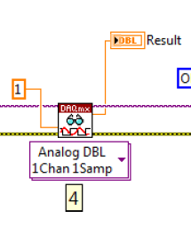
Measure the voltage and the temperature at the same time at the same time. However, when I put the voltage and temperature in a loop, the acquisition of voltage is significantly delayed. When I put the voltage and temperature in two different loop, none of them works. There is an example in aid of Labview as shown. This structure works fairly quickly? In addition, how a volgate get and temperature Analog DBL 1Chan 1Samp? I check the exported excel, the first column is 0, 1 the second column contains the value of the voltage, temperature value. I wonder how can I get these two values for each scan.
,
Assuming that the DAQ cards can handle it, you can set an analog trigger for the channel of the tension. Then you just X samples to get your 100us data value. Keep the last sample.
-
Acquisition of data ongoing and finished at the same time
I have a reading program in the measurement of the temperature of thermalcouples and I currently have my system set up to take a finite number of samples. During the acquisition, I am unable to see the data in the front panel and I want to put in place a way to visualize a graph of continuous for my data waveform is sampled so I can look to find errors. Is there a good way to do this?
You cannot view the data until it was acquired. It is the programming of the acquisition that is at fault. If you want to see it sooner, change the number of samples or the sampling frequency. With a graphic instead of a chart, you can simply change the number of samples and get a continuous display.

Maybe you are looking for
-
I have 4 email address in Thunderbird. How can I add a password for the fourth? It is easy to remove, but I do not know how to add or change. My provider is TurnkeyMail. They say they do not know how to help me and I have to ask to Thunderbird.
-
Got a new laptop, has win8.1. I am able to go down to win7?
Hey thanks for the research. I just got a HP Envy 17-j184nr. It comes with Windows 8.1. Nice series. But I perfer Windows 7 plus 8/8.1. I am able to go down? I know on another hp computer in my house (among the less expensive, under $400) you can not
-
Win 7 home Prem struggling to load.
-
I recently downloaded windows 10 update to GET WINDOWS 10 App, but after downloading completely, the upgrade process stuck. Windows Update is now show "Preparing to install" and it's stuck now. Please help me solve this problem!
-
Porting my apps Playbook to BB10
Hello... I want to update my Playbook applications to devices next BB10... but I'm confused about the resolution of the screen of the devices... I have the alpha of dev which has a large touchscreen display, but also a bold 9900 which has 2.8 inch sc