Sensor mapping VI Express performance degrades over time
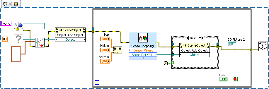
I was trying to make a visualization 3d of some data from the sensor. I did a template and was able to use with the 3d photo tool sensor mapping Express VI. Initially, it seems to work perfectly, and I started to increase the scene with other objects to improve the user experience. Unfortunately, I think I am doing something wrong, at this point. When I add the map sensor object to other objects, something like a leak memory occurs. I'm starting to experience the degradation of performance almost immediately.
I don't know how I should add to better add in reference of the Map sensor to the scene as an object. Normally, I create these child relationships first, before doing anything to objects, beyond creation, movement and anchorage. Since the map sensor output reference is available only AFTER the express vi run. My compromise solution, currently, is to have a case statement of controlled by the constant "First Call". So far, the performance seems to be much better.
Does anyone have a better solution? Am I even manipulate these objects the way the t community - it?
EDIT: Included the vi and stl files.
I agree with Hunter, your current solution is simple and effective, and I can't really see a much better way to accomplish the same task.
Just as a side, note the simplest and the easiest to force the order of execution is to use the error on the functions and the screws in your block diagram. From here with an example based on the VI VI you have posted. (If you paste the image into your drawing, you can make changes to the code)
Given that you have expressed an interest in the documentation links to 3D image controls, I did some research and found a few articles that might interest you. There is nothing terribly complex, but these should be a good starting point. The first link is a URL to the thread of research, so you can get an idea of where this that I'm looking. You will get more hits if you search of ni.com rather than ni.com/support.
http://search.NI.com/nisearch/app/main/p/q/3D%20picture/
Creating a scene in 3D with 3D picture control
Configuration of a 3D scene window
Using the 3D picture control 'Create height field VI' to convert a 2D to 3D image textured heigh...
With the help of lighting and effects of fog 3D Picture Control
3D picture control - create a moving Texture using a series of Images
Change of set and the background of the 3D picture control
Tags: NI Software
Similar Questions
-
This is driving me crazy!
So, I have a reliable internet connection. I start the speed test and get ~ 85 Mbps down. Then slowly, it's even worse, down for like .05mpbs. Until I turn the wifi on my computer, then it is fast again. It can be as fast as 10 minutes - 2 hours.
#1 idea:
Something is sucking my internet connection.
I used every tool under the Sun, with more success with Little Snitch. Nothing uses my connection when it is slow. The fan is off. Computer does nothing.
#2 idea:
Something on my network is using my connection.
Speedtest.NET my girlfriend is fast. My iPhone is fast. Just my computer is slow.
I blame this on my router for centuries, but it does not explain why my girlfriend is fast. So I bought a new router (nine Airport extreme), nothing works.
Yet once, turn/turn on wifi it solves every time. Right of return up to 85mpbs
I have tried everything I can find online, and I'm about to pull the hair last out of my head.
Thanks for any help
MacBook Air, OS X El Capitan (10.11.5)
What is an independent separate cable from the router modem?
Ah yes I see it now
Speedtest.NET my girlfriend is fast. My iPhone is fast. Just my computer is slow.
This corroborerait not a defective modem / intermittent
Try running the AHT http://support.apple.com/kb/HT1509
-
Why performance degrades overtime when insert/update/delete VARBINARY?
I use TimesTen directly related. I created a table with a column of type VARBINARY (100000). My test program inserts a line of 8K bytes in this table, then updates that row with another 8K bytes, then finally deletes this line. If I do the insertion/upgrade to update / delete 10000 times in my program, the number of performances is about 8000 operations per second. But if I do 300000 times, performance is about 4000 transactions per second.
I do not understand why the performance degrades over time? Anyone understand it?
Thank you!
Published by: user8224303 on June 18, 2009 12:41
Published by: user8224303 on June 18, 2009 13:28Based on the workload that you describe, and the fact that you see LOG_BUFFER_WAITS increasing this is likely to be the main problem here. Increasing the size of the log buffer and the size of the file should reduce or eliminate this problem. Depending on the type of disk array and how it is configured, you can still see a performance impact when checkpoints occur if the log files are on the same set of disks than the newspapers. Let us know how you go.
Chris
-
Configuration sensor mapping VI window freezes every time that a. STL file is loaded
The sensor mapping VI gets frozen every time I load a .stl file and the black screen does not appear any model of representation. On the other hand, the same model in a .wrl format works very well. Could someone help me with this problem?
I have the evaluation version of LabVIEW 2010 SP1.
Thanks in advance.
Hi uxpro
I think that you can have your .stl file in a binary format instead of an ASCI format, perhaps that is the reason of the gel
Concerning
Julio Mena
-
Advice on the restructuring of code to avoid the downturn over time
Hi, I am a new user of LabView, you want some advice on how to better structure the program I wrote and which is used to perform a hydrostatic test arrangement. Data are collected on a module of AI cDAQ 9207 and a cDAQ 9474 module is used to control the two valves that subsequently controls pressure in and out of the test Chamber. I enclose my first version of the reference code.
What the VI is supposed to do when the user of the weapon system and strikes then the execution, the program switch will cause a transition of the test chamber through several States corresponding to the levels of different pressure for some time. Time curve vs pressure is written to a file of measures. I built using a state machine structure.
My problem is, during the initial trial, when the duration of the test was about 5 minutes or so, the program went very well. However, once I started to test the length of the actual test of 2.5 hours, I noticed the program running slower and slower as time progressed to the point where it would take several seconds for each iteration of the loop, then by accident about an hour or two in the test. After scouring the articles and messages, I suspect the main culprit is the diagram of waveform and to a lesser extent DAQ assistant.
While I need the loop structure data collection and case to run pretty quickly (preferably the order a few hundred s/s) I need the code to be able to react to changes in pressure in the room quickly enough, the actual data, that I need to store and display the graph can be as slow as a sample per second or even longer. My guess is at this point that I have to rebuild the program using some sort of architecture of producer/consumer, I'm looking for some advice on how best to structure the program.
Data acquisition obviously belongs in the producer loop that will run at a fast enough pace and there will be a consumer loop that will run at a much slower pace for the Bulletin Board writing to the extent of the file vi, but where should I put the case of structure state machine which currently controls the valves? Should put in the loop of the producer since it must run at the same fast pace as the collection of data, so it can react to changes in pressure or should I build another loop of consumer for him? What other indicators (pressure and Boolean) and controls on the front panel, they should be on another loop operating at a medium speed I want to respond to a faster pace than the data to the chart/write the loop, but they do not need to be as fast as the data acquisition loop?
Finally, I'm not quite sure what would be the best way to reduce the sampling rate of the data that I have in fact appear on the graph and the store in the file, it wouldn't make sense to create another task of measurement that samples at a rate below just for that purpose. Suggestions and advice would be greatly appreciated! Thanks in advance!
Bob
My guess is that if you monitor the use of memory over time, you see that going up, Yes? Everything is is always a good idea to get rid of the express VIs, I would look for the problem of slowdown in the structure of the case. You repeatedly open and never close tasks which are created using some DIO channels. Hnece each time that the loop more memory is allocated. Try to move creating channel screws out of the loop, then the tasks are created once before the start of the loop and then written to as required inside the loop - and don't forget to delete tasks once the loop over.
Mike...
PS: You are right with your comments regarding the structure of the producer consumer. Basically it break up as things get quickly (DAQ IO) that there is in a loop, while the user interface and the stuff that can take a long time (such as the data record) are in another loop. You can even have three loops with one for the acquisition of input data and the other for the digital output.
PPS: Finally don't forget that even if the structure of consumption of the producer is usually represented with everything in a single diagram, there no need to be. I wrote a lot where each loop is in his own VI which is run dynamically, then the application starts.
-
full waveform graph to calculate the area under the curve over time
Hello
If please find my attached VI and help me please for integration to get area undercut for my chart of waveform.
I would like to find my wave power wind energy production chart oever within one month of time.
I think I have to integrate to get the area under the curve and so I m now using tool integrated into labview attached.
As I did not wait years for my result and so I want to make sure that the tool that I m using is correct.
Please advise me what method I will use for my chart.
Dominique says:
I would like to integrate my table of power over time (table of power is on each interval of a minute) and the entire graph is one month. So, I'll put dt = 1?
You put dt at some units you want in the final result. If you want Wh, you want dt in hours. If the spacing is currently a minute, you can express in fractional hours and use the result as dt. Try dt = 1/60.
-
I'm trying to use a 3D picture control to draw a simple geometric object (a cube) and then draw the measures that took place within this object. So, basically, a field of 4 d. I read the workout at http://digital.ni.com/src.nsf/websearch/624DF39F2EBF492E8625738A006F0D42?OpenDocument&node=203014_us who showed me how to create the cube. I also found this example of sensor mapping http://decibel.ni.com/content/docs/DOC-2059. It's about what I want to do, but I don't have a template file. Is there a way to add values of sensor for a 3D picture control when you do not have a .stl or .wrl file? Does anyone have examples? Thank you.
Hello
You can return to the example of trace of 4 d following the link:
Plot of 4 d, a level 3 data from freedom from time
http://decibel.NI.com/content/docs/doc-9291It seems the task you are trying to achieve? This example uses additional features of the 3D picture control palette, as opposed to the VI of mapping of the sensor. To properly place and restore the data from the sensor, we would need to generate a load of basic with the sensor mapping VI model file.
Please post back you have any additional questions.
See you soon!
-
First Pro CC 2015.0.1 performance degradation
May have figured out the answer, but maybe ask here anyway will help others...
Background: race Windows 7 Pro on an Intel Core i7 to 4.0 Ghz processor, 16 GB of ram; PNY/Nvidia Quadro K2200, 4 GB of ram. three 2 TB Western Digital Black HDs put in place for performance (as I read somewhere..).
Project is really minimal. All Canon 5DM 2 (*.) MOV clips) from 6 to 10 minutes each. Now to eight sequences, more than one to three separate clips, about 14 minutes longer. Audio is of the clips only.
Get all the clips to each new sequence: Motion/scale 105 and Motion/Rotation-1, 0; Color Lumetri; Unsharp mask; Volume control; Vocal Enhancer; and a low-pass filter on them. Some of the specific parameters (in particular, Lumetri color and low-pass filter) are adjusted back within a single sequence.
As I continue to add footage and edit each, I see a gradual but a degradation in performance deep, to the point that the last two sequences can't play the 'Fit' and 'reading of 1/2 resolution' without stopping every second or two, sometimes for four or five seconds. I'm * not * do the death "Has become" refractory Glas.
All sequences have the infamous "Red Bar".
As soon as I 'Render effects in work area' the red bar turns green and I seem to be good to go.
So, questions:
(1) if I know I'll apply the effects specific to all the clips to each new sequence, just do that, rendered effects just here and before I do all the detailed changes and pick up a cup of coffee until the new sequence has a green bar?
I think I know the answer to that, but confirmation would be appreciated.
(2) effects that I use on each clip, which struck such a deep performance: effects on the video itself, or on the audio?
Again, I think I know the answer to that, but once again confirmation would be appreciated.
Then:
(3) is the Premiere Pro keep track of * all * another non-rendus sequences and clips, so that even if I'm working only a sequence at the same time, all previous, unreturned sequences (their presence is kept in memory, or in a file somewhere that is constantly struck on) are slow and cumulative performance, such as the harder I work and add new sequences , more performance degrade until the PP is simply unusable. Again, this is * not * a project complex, by any means. I do not understand why work on the eighth or ninth sequence causes such a performance deeply moved when working on the first or the second does not.
If this is the case, a revision of software might be in order, such as immediate execution is only affected by the not rendered clip, one that is being developed at the moment.
1 n ° make your changes first, and then add the effects when you're done editing and export loans.
2. sharpness filter.
-
Hello, I am working on an audio model. I'm doing a waveform similar to that which you can see soundcloud. I managed to program an expression to generate the waveform. But I have a problem with filling the waveform with a color based on the time. For example, see you on soundcloud how the waveform fills orange along the song? This is the concept, I am working on that. Here's what I have so far:

I want the blue bar to move to the right over time, but I want only the white parts of the wave to turn blue it progresses (the rest of the hidden solid blue). How would I go to do this? My knowledge in After Effects is limited, so any help is GREATLY appreciated! Thank you
Please let me know if you need more information
So just to clarify you are trying create a representation of levels for the duration of an audio file and not an animation audio frequency analysis. If that's what you do just before compose hundreds of layers, or nest the comp in your main comp, then use the cache by approach. If it was me I would probably just import the audio layer in the comp, press the L key twice to reveal the audio waveform, press on the ~ key to make complete timeline screen, expand the waveform, take a screenshot, add the screenshot to the model, apply Keylight, then add a shape layer below the screenshot set the screenshot as a reverse alpha cache approach for the animated gradient and be done with it. This model should be nested in my main computer to complete the effect.

If I wanted a different look for the waveform I edit the screenshot in Photoshop or use a Premiere Pro or any other program to capture a screenshot of the wave. Since you did all the work of your hundreds of layers I just would compose before them, place a layer of shape with a gradient animated below the pre-comp and put in place the track matte.
-
Since the installation on my Windows 7 64 - bit installed, Firefox has constantly gotten slow that hour passes, hangs for 10-15 seconds at a time and just gets worse over time with updates and all. It was fast when I installed first, but of the six latest mos has slown to a crawl.
upgrade your browser Firefox 8 and try
-
Can I create a spreadsheet to track events over time? If so, how?
Is it possible to use the numbers to track events over time? Dates would be the only numbers you use.
Can you give more details on what you are looking to do? Surely you don't want only a column of dates...
SG
-
Want a ramp of output voltage over time and measure input 2 analog USB-6008
Hello
I want to produce an analog voltage output signal that increases over time with a certain slope, which I'll send in a potentiostat and at the same time I want to read voltage and current (both are represented by a voltage signal) that I want to open a session and ultimately draw from each other. To do this, I have a DAQ USB-6008 system at my disposal.
Creation of the analogue output with a linear ramp signal I was possible using a while loop and a delay time (see attachment). Important here is that I can put the slope of the linear ramp (for example, 10mV/s) and size level to make a smooth inclement. However when I want to measure an analog input signal he's going poorly.
To reduce noise from the influences I want for example to measure 10 values for example within 0.1 second and he averaged (this gives reading should be equal or faster then the wrong caused by the slope and the linear ramp step size.) Example: a slope of 10 mV/s is set with a 10 step size. Each 0.1 s analog output signal amounts to 1 mV. Then I want to read the analog input in this 0.1 s 10 values)
Because I use a timer to create the linear ramp and the analog input is in the same loop, the delay time also affects the analog input and I get an error every time. Separately, in different VI-programs (analog input and output) they work fine but not combined. I searched this forum to find a way to create the ramp in a different way, but because I'm not an experienced labview user I can't find another way.
To book it now a bit more complicated I said I want to measure 2 input analog (one for the voltage of the potentiostat) signals and one for the current (also represented by a voltage signal) and they should be measured more quickly then the bad of the analog signal. I have not yet started with because I couldn't read on channel work.
I hope someone can help me with this problem
An array of index. You want to index the columns for a single channel.
-
Plotting the amplitude of a spectral peak over time
Hello
I am creating a VI where the acquired continuously DAQ, plots and save a waveform in millisecond delay (which is already done in this case), then takes this waveform, finds a specific pic (probably the first) and trace the amplitude of this pic over time (+ 30 minutes, one point each scan which is obtained). Essentially, I have a detector quickly attached to a chromatograph, and I want to select a single ion and monitor the amplitude of this ion. I can draw the waveforms along with it in post processing, but I want to do is to have the 'slow' constantly plot to update and display when it moves through time. Joined the VI will go in, using IMS software V1.3.vi, the paragraph is the "GC" Mode it seems I should use the "peak detect.vi.", but I'm not familiar with this operation, and so I don't know how to show a constantly updated graphic or remove the amplitudes and draw. Thank you for your help,
<><>
Eric-WSU wrote:
I get an amplitude on plot of time, but it does not appear until after all the iterations are stopped
I have not watched your VI (because I'm in a previous version of LabVIEW), but it's probably because your graphic is outside the loop.
Here's how you can get a graph of the peaks (all vertices, by iteration):

Or if you want to only a certain PEAK (and how this pic changes with the number of iterations):

-
Hi, I have two decimal strings, each of them contains the numbers change over time. I want to plot them on the graph XY, a string for each axis. Can you show me how do?
This is not a formula, but a constant simple schema of a table complex. Wire remains, then do a right click of the terminal of the initializer of the feedback node and select "create constant. That should do it.

-
Get information from change of color over time
Hi all
I am new to LabView and on this forum, so I hope I'm in the right subforum. If this isn't the case, it would be nice if a mod could move this thread.
My problem is the following:
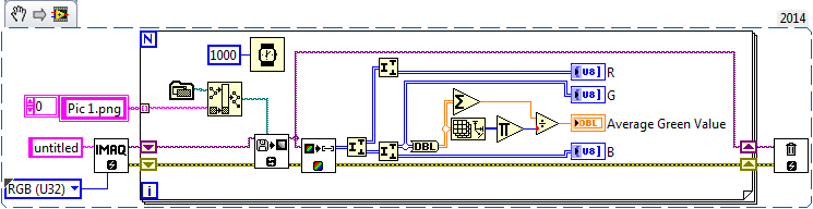
Let's say I have a white spot I want to observe with a camera. The color of the spot turns green over time and I want to acquire the photo, as well as to get the color intensity of green increase developing countries over time. I do not know what features I need to use to get there. Can someone me hint in the right direction? I think that it is at least possible in LabView.
Thank your all for your help.
Best regards
Tresdin
I don't know what the best resource for IMAQdx pilots, I think that the examples that provide OR are pretty useful. Here's a simple VI which will tell you the average value of green of all the pixels in your image.


Maybe you are looking for
-
For some reason any bar type appears on Web sites and is not allowing me to use scrolling properly the top and bottom of the page. It is present at each Web site. However, when I switched to another browser it can't.
-
How can I recover password forgot iPhone 6 more without losing everything that is on my phone?
How can I recover password forgot iPhone 6 more without losing all the content on my phone?
-
Turn display only notifications
find boring, as the screen lights up to put my hand sometimes find myself driving or working and the screen lights up, I turned off the automatic display of ignition, but at the time of the notification, I have to press the screen, if requested, I do
-
Phone call suspect on malware virus. Should I have one?
I received a phone call from "Gary", who said he was from Microsoft and that I had a malware virus on my computer and it should be supported until my computer became free. He took me to the beginning/right clik on my computer/manage/event viewer/app
-
descargar windows 7 ultimit con mi product key
descargar windows 7 ultimit con mi product key