Sensor mapping
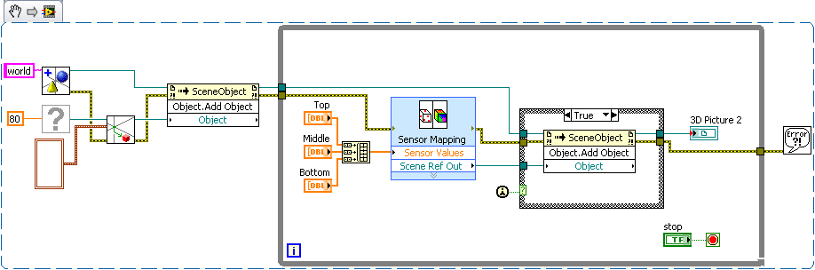
I'm trying to use a 3D picture control to draw a simple geometric object (a cube) and then draw the measures that took place within this object. So, basically, a field of 4 d. I read the workout at http://digital.ni.com/src.nsf/websearch/624DF39F2EBF492E8625738A006F0D42?OpenDocument&node=203014_us who showed me how to create the cube. I also found this example of sensor mapping http://decibel.ni.com/content/docs/DOC-2059. It's about what I want to do, but I don't have a template file. Is there a way to add values of sensor for a 3D picture control when you do not have a .stl or .wrl file? Does anyone have examples? Thank you.
Hello
You can return to the example of trace of 4 d following the link:
Plot of 4 d, a level 3 data from freedom from time
http://decibel.NI.com/content/docs/doc-9291
It seems the task you are trying to achieve? This example uses additional features of the 3D picture control palette, as opposed to the VI of mapping of the sensor. To properly place and restore the data from the sensor, we would need to generate a load of basic with the sensor mapping VI model file.
Please post back you have any additional questions.
See you soon!
Tags: NI Software
Similar Questions
-
Sensor mapping VI Express performance degrades over time
I was trying to make a visualization 3d of some data from the sensor. I did a template and was able to use with the 3d photo tool sensor mapping Express VI. Initially, it seems to work perfectly, and I started to increase the scene with other objects to improve the user experience. Unfortunately, I think I am doing something wrong, at this point. When I add the map sensor object to other objects, something like a leak memory occurs. I'm starting to experience the degradation of performance almost immediately.
I don't know how I should add to better add in reference of the Map sensor to the scene as an object. Normally, I create these child relationships first, before doing anything to objects, beyond creation, movement and anchorage. Since the map sensor output reference is available only AFTER the express vi run. My compromise solution, currently, is to have a case statement of controlled by the constant "First Call". So far, the performance seems to be much better.
Does anyone have a better solution? Am I even manipulate these objects the way the t community - it?
EDIT: Included the vi and stl files.
I agree with Hunter, your current solution is simple and effective, and I can't really see a much better way to accomplish the same task.
Just as a side, note the simplest and the easiest to force the order of execution is to use the error on the functions and the screws in your block diagram. From here with an example based on the VI VI you have posted. (If you paste the image into your drawing, you can make changes to the code)
Given that you have expressed an interest in the documentation links to 3D image controls, I did some research and found a few articles that might interest you. There is nothing terribly complex, but these should be a good starting point. The first link is a URL to the thread of research, so you can get an idea of where this that I'm looking. You will get more hits if you search of ni.com rather than ni.com/support.
http://search.NI.com/nisearch/app/main/p/q/3D%20picture/
Creating a scene in 3D with 3D picture control
Configuration of a 3D scene window
Using the 3D picture control 'Create height field VI' to convert a 2D to 3D image textured heigh...
With the help of lighting and effects of fog 3D Picture Control
3D picture control - create a moving Texture using a series of Images
-
Configuration sensor mapping VI window freezes every time that a. STL file is loaded
The sensor mapping VI gets frozen every time I load a .stl file and the black screen does not appear any model of representation. On the other hand, the same model in a .wrl format works very well. Could someone help me with this problem?
I have the evaluation version of LabVIEW 2010 SP1.
Thanks in advance.
Hi uxpro
I think that you can have your .stl file in a binary format instead of an ASCI format, perhaps that is the reason of the gel
Concerning
Julio Mena
-
Hello
I'm using Labview 8.5 to work. As you may already know, versions 8.6 prior have a 3D sensor mapping feature, which can help a lot with the development of a project.
However, I need to explain how it works in order to have authorized a purchase or an update of our LabVIEW liscense, to obtain a more recent version. We already have a source program closed for sensor mapping, we don't know even what technical mathemathic uses to map data, or can modify it to fit our needs.
Just knowing the names of the techniques of interpolation/extrapolation/one other-math or indecipherable are used to map between the two parties, the model and sensors, would be sufficient.
Thanks in advance.
Hi tunario
It uses an algorithm of linear interpolation basis, and if you want to have access to interpolation VI sensor mapping Expresss VI uses you will need to follow these steps:
- Place a sensor mapping Express VI on the block diagram
2. right click on the VI and select open the front (this will convert the express VI format so we can view the block diagram)
3 inside of this VI, open the Update Mode.vi
4. in the top of the structure schema-block case page, you will find a Subvi, called interp.vi5. This is the VI which is used to interpolate values for the mapping.
I hope this is enough and if you need anything just ask.
Brenda
- Place a sensor mapping Express VI on the block diagram
-
Intensity on a model 3D mapping
Hi all
I am doing a project which corresponds to the intensity in some positions of a 3D model.
I've tried sensor mapping an Express VI. It's exactly what I want to do. But I have to change the configuration of the double click on the VI in block-scheme, and I can't limit the range of intensity one probe.

So, I want at least to change the model or the positions of the sensors on the front without stopping the program and opening in the block diagram. And it will be perfect if I can limit the intensity range.
Please help me solve this problem. It is not required to use the map sensor.
Thank you very much!

No, the only way to change the configuration of this particular VI is by double-clicking on it when the VI is stopped. If you had a list of values that you want to use, you can create multiple instances of the VI, and each of them would have a different configuration. You can then place them in a case structure and then use a control on the front panel to select which configuration you want to use. Basically, you'd have a different configuration for each case. It's the only way I can think of that would allow you to work around this problem.
-
Missing screws in the 3D 2010 image control?
Hey everybody,
I tried to follow this guide to the developer for visualization of Labviews functions:
http://zone.NI.com/DevZone/CDA/tut/p/ID/7664
I discovered that many screws shown here for 3D picture control are not available for (free) module in Labview 2010, even with the control and simulation tool. What is the case for other users?
Examples of 3D picture control screws that I can't find in Labview 2010 block diagram functions are:
'building of toroid.vi '.
'create model.vi '.
'Add a material.vi '.
'Create transform.vi '.
'Add a model.vi '.
'create camera.vi '.
«camera look at.vi»
'create positional light.vi '.
"make scene.vi".
"to scene.vi".
However, I can find the following screw:
Geometry menu
'create cone.vi '.
'create cylinder.vi '.
'create box.vi '.
'create the height field.vi '.
'create mesh.vi '.
'create sphere.vi '.
'create text.vi '.
Object Menu
'create object.vi '.
'find the object.vi '.
Transformations menu
"to rotation.vi".
"set rotation.vi".
"rotation object.vi.
"to scale.vi".
"set scale.vi".
"Object.vi scale".
"to translation.vi".
"set translation.vi".
"translate object.vi.
'clear the transformation.vi '.
Menu of aid
"color change.vi".
"configuration window.vi".
'create a clip plane.vi '.
'texture.vi '.
"new light.vi".
"sensor mapping.vi.
File loading menu
«load ASE geometry.vi»
'load the file.vi vrml ".
"load STL geometry.vi".
So my question is why can't I access the first list of the screws in 2010, are hidden with screws again features somehow? Or am I missing a library or where these functions abandoned for the 2010 version? If they have been abandoned, is it possible to build a scene and drawing from scratch in the 2010 version?
Thank you very much!
Hello
Control of the 3D image is natively available for LabVIEW 2010. The question that you are running is because you try to open a VI that uses the first NOR-Labs 3D Picture Control, which was replaced by the native 3D image control. These functions are "obsolete" and manually replace your code with new API of navigation. You can also try using the old Toolbox, but keep in mind that this is not supported:
http://zone.NI.com/DevZone/CDA/tut/p/ID/4411
Examples of the new API is located in:
C:\Program NIUninstaller Instruments\LabVIEW 2010\examples\picture\3D Picture Control
and you should be able to find most of the VI need to change your old Toolbox to the new.
I hope this helps...
-
Modules to relay 'High tension' OR USB can be used to pass ultrasound
A researcher needs spend a single driver/sensor map ultrasonic transducers. Ultrasonic excitation is pulse frequency reaching hundreds of volts. OR devices such as USB-9481 are called 'high voltage' but are evaluated and only 250Vrms for 30 VDC switching, I guess that it wouldn't work... NOR has it any solution based on the USB that can cope with high frequencies and high voltages?
Hello Stringman
I don't think, but I'm curious to know what is your required specifications. I would recommend and isolated relay controlled by Council USB - 6501 DIO if software trigger is not a problem, or can use their USB DAQ card M-series switch or OFF your external relay.
Good luck
Lab
-
Correction of the lens for Tamron 17-50 2.8 could be better?
 This is WITHOUT the lens profile correction.
 ... and that's WITH the lens profile correction. Not very obvious, isn't it?
Upper right corner of a photo taken with the Tamron 17-50 2.8 at 17mm 5.6.
The cut isn't right but a funny!
Most likely, the slope of the cut in the corner of the image is not created by the distortion of the lens, but the camera pointing down.
When the camera is not required to level but pointing upwards or downwards, the sensor is not in parallel with the vertical lines of the Cup. It is the phenomenon of "Scheimpflug" - google for this word and you will get many results. The phenomenon of "Scheimpflug" becomes stronger towards the edges of the image.
That's why the architecture photographers use "see photo" where you can adjust the angle of the plane of the film or digital sensor map so that it is parallel to the vertical lines of a building.
You can adjust the tilt of the cutting with the manual vertical slider in the Correction of the lens, and you may need to adjust the horizontal slider as well. The compromise is now, your image will be severely "trapezoidal" and it's probably not what you want.
But you can't blame the lens profile. Profile lens corrects only distortion of the lens, no distortion by the principle of "Scheimpflug.
PS: A tilt-shift lens will also correct the distortions of the principle "Scheimpflug.
-
error message when the location of my pictures (Google maps)
Excuse my bad English, I'm french! When I try to inform them of the location of my pictures in IPhoto, using Google Maps in the Info window, I get this message: "Oops!" something was wrong. This page has not properly loaded Google maps. See the JavaScript console for more technical details"
What can I do with Java script?
Thank you for your response.
Contract of Apple with Google to use Google maps with locations of the pictures in the iPhoto library has been cancelled a few months previously. That's why iPhoto 9.4.3 and earlier can no longer access the Google map servers and get this error message.
If you use iPhoto 9.4.3 or earlier you can stop the fracas in the following manner, but will lose the mapping functionality in the library.
iPhoto 9.4.3 and earlier began planting for many users suddenly a few weeks ago. This is because the contract between Apple and Google for the use of Google maps with iPhoto 9.4.3 and earlier sites expired an elderly couple of months and was not renewed. This is the case of him freezes or crashes.
Now uses Apple its own program for locations maps and too the use you need to run iPhoto 9.5.1 and Mavericks or 9.6.1 and Yosemite El Capitan or Photos and El Capitan.
Try Huxly647Solution:
Huxly647 , November 20, 2015 12:05 AM
Re: iPhoto crashes after opening several times in reply to carvermonI found a solution that works for me.
1 goto /Applications/iPhoto.app/Contents/Resources (control (right) - click the iPhoto application and select the content in the context menu - OT.)
2 delete the files 'googlemap.html' and googlesearch.html
iPhoto no longer crashes, site does not work, but it doesn't bother me too much.
Let me know if it works for you guys...
Deletes two files "googlemap.html" and the googlesearch.html of iPhoto application bundle prevents the JavaScript running inside and causing the accident. Log of course do the same thing. So it's pretty clear that something happened at the end of Google.
There is a notch posted by user cotton-x that will let iPhoto 9 and earlier still use Google Maps for the purpose of the location.
16 December 2015 14:49
Re: iPhoto 11 - problems with Photo locations
YES!
I did just the job.
I'm on a macbook running white 10.7.5 with iPhoto 9.4.3
Thanks to Paul, I got an idea. What happens if we had simply ignored Apple has expired API and used our own, private and free from Google. Turns out it works.
Here's what you need to do:
0 - quit iPhoto
1. create a google account or use your own
Console developers of Google 2 - access HERE
3. create a project (any name)
4 - turn on a Google Maps Javascript API
5 - generate your own API key
6 - go to the folder /Applications/iPhoto.app/Contents/Resources/googleMap.html
7. change the googleMap.html (I used an application called TextWrangler)
8 change the src ="http://maps.googleapis.com/maps/api/js?v=3 & client = gme-appleinc & sensor = false" > to this src = 'https://maps.googleapis.com/maps/api/js?key=YOUR_KEY_HERE& signed_in = true & sensor = false ">"
9 - save your freshly edited googleMap.html
10 - open iPhoto and enjoy.
Take the Apple.

Don't forget to make a backup copy of the iPhoto application before performing this procedure.

-
reading two sensors (alternately) in a structure of the event permanently
Hello
I have a structure of event with various functions of the user interface. The entire application is on a laser diode control and playback of two light sensors IR which cover different wavelengths (if and InGaAs). The two sensors are connected to the same AD converter, but to different channels. So if I want to read the two sensors, I have to change the setting of the "Converter" AD channels. The real question is how to implement playback continues two sensors in the structure of the event? I want to be able to read alternately each sensor in a span of 50 or 100 m is possible, another using function of time-out of the structure of the event with a kind of logic xor for switching channels? Maybe something with more features (somehow by a timed loop)?
Any idea is welcome.
Thank you and best regards,
Gregor first
P.s. The sensor reading is done by a National Instruments SPI map where SPI is the master.
2010 VI converted down
-
DAQ 6014 connection with sensor
I have a PCI DAQ 6014, a connection block 68 pins, a DAQAccessory. I want to take the signal from the sensor to the PCI 6014 Iconnected sensor output on the terminal block, then block thisconnection via a cable connected to the 6014 correct? signalfrom voltage sensor, the output pins two-wire in any block of connection. I put in ACH0 and AIGND possible? I don't understand to do data acquisition accessory. its function is like. I don't may not need to use it in this case is not. I thank he replied.
Hi saker.
The standard way to connect your system will be: connect your PCI on your computer, use the cable to connect the PCI card with the accessory and finally your sensor to the accessory.
If your sensor is a two-wire sensor, there are two ways to connect to the map, the CSR and the differential mode, you can find instructions and descriptions on this type of connections on page 2-5 of the manual you can find here. In page 2-21 of the same manual, you will find connection CSR instructions both in differential mode.
So, if you accessory is the SCB-68 box, you might find the pins of device mapped in figure 2 on page 3 of the user manual. This means that the pins in your card will match the pins in your Terminal.
Hope this information helps.
Kind regards
-
USB-6211: analog input signal affecting another of the same map AI
Hello
I use the DAQ-nor-6211 map and DAQmx features to read a hammer and a signal of the accelerometer and then use other LabView functions to make the FFT of these analog input signals. However, it seems that the analog inputs where the hammer and the accelerometer are connected generate a kind of noise or influence in other entries of this data that is not connected to any other sensor acquisition board.
I've had different experiences in order to check if the problem is with reading the card: put the accelerometer and hit the dog in another table where the DAQ card table was located (to avoid the vibrations on the map and a possible noise), ai1 entry was logged on the differential mode on the dog and the ai4 of entry is connected to the output (z axis) of the accelerometer. The other 2 ai2 and ai3, entries that can also be read by my LabView program, are open (i. e., any other sensor is connected to the card). When the structure where the accelerometer is located is struck by the hammer, the signal of ai2 ("x axis" seen in the first attached document) has a curve (on the time domain) which initialize almost at the same time that the hammer and the a3 of entry has a weak signal, but with the swing as well as the signal of ai4. The document "hammer ai1 + z_axis connected_ _x_axis disconnected ai2 + y_axis ai3 ai4" images that I captured the chart created in LabView. On these graphs, it is possible to check on the FFT the ai3 signal and ai4 has the same behavior (with different intensities), and enlarged figure of time domain image, we can see that the signal of ai2 increase almost at the same time of the signal of the hammer (ai1). The signal picked up by the sensors are probably creating a sort of noise on open entries ai2 and ai3.
Another experiment was conducted to check if the signal from a single entry that may affect the signal read from each other near the entrances: the DAQmx task Create channel had a physical channel has changed: ai3 entry has been modified by ai7 (maintain the same connection mode: differential), and the results are visible on the second attached document. In the graphs obtained in this experiment, it seems that the entrance of the hammer (ai1) affects the signal of input ai2 and ai7, which are not connected. And the ai4 signal does not seem to influence the other inputs, because he has a different curve on the graph of the FFT.
The same experiment was conducted using the CSR connection (change threads and create the DAQmx Channel Configuration), but the results were the same as those found using differential connection.
Finally, if the output of the accelerometer is connected on the ai2, the signal of the other open entries ai4 and ai7 seem to be affected by the signal of the accelerometer on ai2 (last document attached).
Could you tell me if the problem I encounter is caused by the DAQ card with this information that I gave to you? And if the answer is Yes, do you know if there is a way to avoid this noise create in one entry on the other hand, it please?
Thank you
Maybe Ghosting or crosstalk? Just an idea.
-
RTD & Thermocouple sensors Simulation
I am very new in VeriStand, and I would like to ask you what is the best way to implement simulation of VeriStand sensors.
I should implement simulation of RTD and Thermocouple VeriStand probes.
Problem with temperature sensors are mathematical equations has high order (RTD's 3rd order (it is not so bad) and Thermocouple is 9th order).
What I have to put in place this equations on FPGA or VeriStand could calculate for me in the real-time engine (and then VeriStand implement on FPGA and channel AO level could be applied only something like reaction/compensation currents of excitement to HAVE it)?
What is the common practice to implement simulation of temperature sensors. Of sampling/update for temperature sensors is generally very low.
My configuration is:
- Home PC - development tools
- PXI controller - OR VeriStand engine RT
- RECONFIGURABLE - PXI map
- NI9151 - R series expansion chassis
- C - Series AI & AO (electric implementation)
I'm looking forward to you answers.
Peter (CLA & CTD)
Thermocouple (9th order) I have implemented on FPGA as a look up Table. Look-up Table initialized by the equation of order 9th in the range of the required values.
RTD (3rd order) directly implemented on FPGA. VeriStand send all settings from all periods.
-
How to use HX85BA sensors with NI DAQ system?
Hello
I'm trying to connect two sensors of Omega HX85BA moisture to my NI DAQ system. The sensors detect moisture, barometric pressure, and temperature, using three 0 to 10 VDC positive outputs @ 10 mA or less, with a common thread of output. I have a SCXI-1000 chassis with two modules SCXI-1100 cards, 1102 b and a single 1102. Map of 1102 uses a block to connect SCXI-1303, while the other three cards use some 1300 years. The system will mainly use thermocouples for temperature measurements, but there will be other types of sensors, such as the two HX85BAs.
The manual of the product for the HX85BAs is not very clear on how to connect the sensor to the system. Terminal blocks each have 32 channels with the positive and the negative screw terminals, it doesn't connect three positive sensor outputs to individual channels, with the municipality of output connected to each channel? It will work installation with SCXI cards I have, or I will have to purchase different cards? The system will be expanded to include at least 4 cards in a separate chassis SCXI 1000 more, is not a problem for the purchase of different components to adapt to the HX85BAs.
Thanks in advance!
Hi BBalmforth,
You can connect the sensor to the SCXI-1100 1300 TB. Connect the positive output of CH + and CH - CHSGND. Common output wire must be connected to GND.
-
Get a location without GPS sensor? Using internet ip address approximation?
Hello
I'm doing a project with knots of sensors and using the cloud to assist in the management of the energy of the node. Basically, labview must be connected with the node and from time to time receive data. The data are stored in the cloud. Up to this point, all right.
The cloud should also receive GPS location, so if in the cloud, there are these latest data on this gps location, labview who would check and request data on the sensor node (using energy).
My problem is that I don't have a GPS sensor, but I know in the internet, Web sites such as google maps, can approach your location (I believe that through a technique of triangulation ip). So, the only thing I wish is to acquire this information with labview real-time. How can I do?
Of course, you can always try using the services of google API's location: https://developers.google.com/maps/documentation/geolocation/intro#wifi_access_point_object


Maybe you are looking for
-
BG.js reports AVG antivirus is or contains a virus
AVG with the latest updates and Firefox 35.0.1.5500 disagree. AVG reports that the bg.js file contains a virus. I would tend to believe that's not true, but just to be safe, we are here. Here is the path: C:\Users\Don\AppData\Roaming\Mozilla\Firefox\
-
When replacing Labview Labview 2014 2013, must I first uninstall Labview 2013?
I just received my latest version of Labview 2014 CD. When you install this new version, must I first uninstall previous versions of Labview?
-
problem w / measure automation explore or/o Inst Asst
Hello I'm new to Labview and I work my way through the tutorial. I loaded 3 disks for measurement Automation Explorer such that I can complete getting started with Labview Ch.4, using a DAQ hardware. The part where I place an e/s of Instrument on the
-
How to remove a contact from the drop-down list?
How to remove a contact when, if forwarding a message, the icon flashes in space 'To' to enter the email address, when you press the first letter of a recipient, it displays a list of previous names/addresses used. This can add to a huge list! Most o
-
How can I restore my PC to last time?
I downloaded a new vertion of the emusic handler and now everything is locked up. I'm afaid if I have an install emusic manager all together it can destroy my music. I wanted to restore my HP Pavilion Slimline s5220f running windows 7 to a permeable