Sensor use the NDK 2.0 in a (ANE) Extension Native AIR API
Hello
I tried to access the gyroscope for a Native Extension of AIR, help NDK 2.0 Beta 3, Flash Builder 4.6 and Tablet OS 2.0.0.7111
I managed to make a C simple library that I can call the air (so that I don't know that all the settings are correct), but as soon as I add a reference to the sensor.h library loads is no longer. I get the following error in the AIR:
ArgumentError: Error #3500: the context of the extension doesn't have a method with the name of init.
at flash.external::ExtensionContext/_call()
at flash.external::ExtensionContext/call()
to com.adobe.nativeExtensions::Gyroscope$/get isSupported() [/ Users/airqe/Users/sbhave/Gyroscope/AS/src/com/adobe/nativeExtensions/Gyroscope.as:106]
...
My assumption is that I'm using a library which contains functions of sensor is not found, so it cannot load my library. But I can perfectly well be another problem.
Someone has managed to make this work? Any help would be welcome.
Thank you!
I just added bps in libraries (-l) the GCC linker settings and it works.
Thanks for the explanation!
Tags: BlackBerry Developers
Similar Questions
-
Compilation error when you use the NDK library
Hello
I am developing an application of cascades that uses a static library NDK to communicate with a bluetooth device. The NDK library compiles without problems, but when I then compile the application stunts I get errors with all bluetooth NDK functions:
myBB10Lib.a(BluetoothDevice.o): In function `MyBB10Lib::BluetoothDevice::getAddress()':
\src\Driver/BluetoothDevice.cpp:33: undefined reference to `bt_rdev_get_address'

myBB10Lib.a(BluetoothDevice.o): In function `MyBB10Lib::BluetoothDevice::getName()':
\src\Driver/BluetoothDevice.cpp:53: undefined reference to `bt_rdev_get_friendly_name'

make[2]: *** [o.le-v7-g/MyCascadesProject] Error 1
make[1]: *** [debug] Error 2
make: *** [Device-Debug] Error 2
(I create a static library as it will act as a driver for the bluetooth device in other applications of stunts in the future).
I have good include (#include
) in the BluetoothDevice .cpp file, but the application of Cascades always gives me this error. It is one of the functions in question: /*! * Returns the MAC address of the remote device, terminated by a null character (\0). */ char* BluetoothDevice::getAddress() { // Holder for results char address[18]; // Perform the check int res = bt_rdev_get_address(mDevice, address); if(res != 0) { //TODO Query failed, pass up error } return address; }Any suggestions?
Hello!
I suspect that the NDK functions can be linked only dynamically. Only the .so files are available.Try adding
LIBS +=-lbtapi
the file .pro of application using the library. -
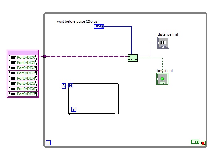
How can I multiplex sensors using the FPGA
Hello
IM using a robotics starter kit and the FPGA chip is too small for the code I try to put in there, so I'll try to do several smaller functions.
I use 8 identical sensors and I am a Subvi, which returns the distance measured and weather sensor has expired or not, but I do not know how to reuse the same function for each sensor.
Can someone help me?
-
Out of reading 2-wire 4-20mA pressure sensors using the NI9203 module
Hi all, I'm sure that a lot of people can give a response would we apply for this.
While looking at the wiring diagram on some pressure transmitters (2 wire 4-20 mA output, direct wire), that I'm about to buy, I noticed a slight inconsistency with the wiring in the NI9203 manual. Here are links to manuals for sensors:
Following the manual of NI9203, the + ve terminal of power supply (24Vdc in my case) must be connected to the Brown Terminal in the transducer and - ve supply ground COM on the NI9203. This leaves the Green Terminal in the transducer must be connected to AI0... AI7 on the NI9203 module. This provision makes perfect sense to me. However, the user for the transducer manual suggests that the Terminal green must be wired to zero volts land i.e. COM. This configuration makes less sense to me.
My question is, the internal electronics of the transducer released still the same my current for the same measured pressure given by the curves of calibration for sensor, even if the Green teminal is not connected to zero volts?
I have a hunch it's okay, but I wanted to be sure before that I lost many years spent money / bad record pressure. This should be a matter for manufacturers of sensors I know, but I found this forum is * much * more useful!
See you soon,.
Chris
Hi Chris,
The 9203 is a device for current descendant be plugged on one side common or 0 volt. You must connect your pressure in 2 wire mode sensor.
+ 24 v DC to the positive terminal on your sensor pressure 1 terminal or brown flying lead, Terminal 2 green flying lead is connected to AIx on your 9203 and the commune of the 9203 connected to 0 Volts on your power supply.
All 2-wire device used in a current input down is still as cable + volts then 2-wire device + then then 2-wire device - (or 0) then HAVE + then common then 0 volt.
In my experience the 9203 can be rather prone to noise pick up devices with 2 sons and need a suitable clean power supply. For 2-wire devices, I take 1024 readings and then averaged to reduce noise.
See you soon
Stephen
-
Update IDSM2 5,0000 S225 to 5.1 using the application partition
can I switch an IDSM2 (WS-SVC-IDSM2-BUN) in a 5,0000 S225 5.1 6513 by copying the partition of 5.1 application on the sensor
[Correction to the userguide cisco]
Chapter 10 Configuring the sensor using the CLI
Modules and devices available
Reimage on JOINT-2
This section contains the following topics:
Catalyst Software, page 10-124
Software Cisco IOS, page 10-126
Catalyst Software
To reimage the application partition, follow these steps:
Step 1 get the file from the software Center on Cisco.com and copy application partition
it to a FTP server.
Step 2, connect to the switch CLI.
Step 3 start the JOINT-2 to the maintenance partition:
cat6k > (enable) reset module_number cf:1
Step 4 connect to the partition maintenance CLI:
Login: guest
Password: cisco
Step 5 Reimage the application partition:
[email protected] / * /# ftp://user@ftp server IP/directory update
file access/image path
Step 6 specify the FTP server password.
After the application partition file has been downloaded, you are asked if you
you want to go forward:
The upgrade will scan the content on the hard drive. Do you want to
Continue to install [y | n]:
Step 7 type y to continue.
When the application partition file has been installed, you are returned to the
maintenance CLI score.
Out of step 8 maintenance partition CLI and go back to the switch CLI.
Step 9 reboot the JOINT-2 for the application partition:
cat6k > (enable) reset module_number hdd:1
Step 10 when the JOINT-2 has restarted, check the version of the software.
Step 11 in the partition CLI application log and initialize the JOINT-2.
Page 10-2, in view of the procedure, see initialization of the sensor.
IF NOT, THEN IS IT SHORTENED 4.1 to 5.1?
I was in the middle of editing my answer when he entered, check again. There is the question of "fact the maint.". partition must be upgraded? "and I have identified patches and GIS level to apply later.
-
How to set the vlan native on a virtual machine in vSphere when you use the 1000V?
Using the General switch original vSphere, we put VLAN native by VM by setting the VLAN 0 d.
How do we set VLAN native for a virtual machine, if the virtual computer is connected to a 1000V? I heard that is over, we can use VLAN ID 0?
Same way as you would on any Cisco switch.
Add this command to your profile of uplink port:
switchport trunk vlan native X
Keep in mind there is no VLAN 0. VLAN '0' is just how vmware means the VLAN untagged. There are valid in accordance with the standard 1-4095.
Kind regards
Robert
-
Use the command line to call EX60/C40
Hello
I'm looking to use the command line or xml to call extensions of our EX60 and C40. I want to automate the call made by the devices. We use 9.1 CM and TC6.
In addition, if someone knows if it is possible to configure ERA/Hot Dial so when a user picks up the phone on the EX60 it automatically connect an extension? I tried through dialing SIP and ERA rule in CUCM.
Thank you
Kaleb
To dial the command line, you can use the command 'xcommand dial.
xCommand Dial
Dial a number from the system. Returns information on the CallId and ConferenceId, which are necessary for some other commands.
Number: Enter the number or address.
Protocol: Select the Protocol h.323 or SIP.
CallRate: Fix a rate of call.
CallType: Select the type of audio or video call.
BookingId: any identifier that an external booking system (e.g., TMS, CTS - MAN) can use for its own references to match calls placed with the internal identifier systems of booking for a meeting. This can be any string, for example, a GUID. The reservation Id will be provided in the call connects, events of appeal etc. for the call.
Requires the user role: USER
Parameters:
Number (r):
Protocol:
CallRate:<64..6000>
CallType:
BookingId:Example:
xCommand Dial number: 543210 Protocol: h323
Ok
* r DialResult (status = OK):
CallId: 2
ConferenceId: 1
* end -
How to use the fingerprints on the Satellite A100 sensor?
Hello
I have a question about my Satellite A100-847. I, near the touchpad, a fingerprint sensor, but I didn't know how to use it. When I searched the technical manual I found that this model he assumes to have this kind of sensor.
Can someone help me with this?Hello
I think the user s manuals document is written for all models (PSAA9E) A100 and they come with a different hardware configuration. According to the specifications of the laptop your model has sensor of fingerprint reader, and you can configure using the preinstalled fingerprint utility.
-
How can I measure the output of a sensor pwm ultrasound using the module or 9403
How can I measure the output of a sensor pwm ultrasound using the module or 9403
Khalil,
When you say 'measure' the PWM signal, exactly what to tell you?
You're looking to measure the frequency or cycle of the signal function? You count the edges of the PWM output increase? Looking to control the waveform?
With reconfigurable FPGA hardware, it is up to the user to define the function of the physical i/o on the FPGA chip. By connecting the signals as Adam suggests your digital pulse will be brought to the cRIO. In your FPGA program, you define the function. You can set a base counter or transfer digital data from single point to welcome you cRIO for floating-point more complex treatment. Example FPGA programs are located in the http://www.ni.com/IPnet.
Hope this helps, please post any additional questions.
-
Troubleshooting for sending data of 16 sensors to an excel using the IO file worksheet
Hello everyone. I'm taking 16 sensor data using multiple analog inputs. The device that I use is a 6210 USB data acquisition module and so far I have further complicated the cause of program, it seems to work when I run. I read that you can add multiple channels to a Daq Assistant and use just this one Daq Assistant for all sensors and use a separate signals function, but I don't know how to write code that can be used for the task of trying to send that data from all 16 of the sensors to an excellent spreadsheet file. If anyone can help by sending a file attached on how correctly, that would be great. I'll put the file attactched down below what I tried to do.
Thank you for all your help.
Start by saying 'never use the DAQ Assistant!'. Instead, read this excellent summary of NOR-DAQmx that tells you how to do almost everything you need quickly and easily. What I suspect you want to do is every moment, taste all 16 channels and bring them into a table of numbers I16 (or, if you have defined scales, as 16 slna in units, you set). You can "wrap" your only playback function of data acquisition within a while or for loop of N samples (for example, until you press Stop), then take the (now 2D) array of N points of 16 channels, and write to Excel.
First of all, to get the data in "better shape", using DAQmx. Have you tried opening MAX and get data by using Test panels? You can see how MAX can taste all 16 channels at once, at the current rate you specify, permanently? You can use MAX to set the scales, and if you perform a task in MAX, you can (when configuring your DAQ VIs) pull down this task already defined-and-configured and have almost all of the configuration done for you by MAX (well, not really for you, but made by you when you have made and saved the task).
Bob Schor
P.S. - These lights on the front panel are a bit garish, aren't they? But very pretty...
-
Can I use the NI 9236 in full-bridge sensors?
Can I use the NI 9236 in full-bridge sensors?
Yes.
-
Hi guys! I am a web-game developer but a beginner in developing blackberry applications.
I intended to create a star atlas application and I've already finished most but failed to use the 'sensors' api.
I referred to the example provided in the documentation of webworks 2.1 as below:
function compassCallback(data) {
document.write("Current azimuth:"+data.azimuth);
}
blackberry.sensors.setOptions("devicecompass", { delay: 1000 });
document.addEventListener("devicecompass", compassCallback);
and I added an element in the config.xml file:
also, I added the plugin com.blackberry.sensors for the project.
But I still can't azimuth compass...
I really appreciate if someone could help me with this!

I solved this problem by myself.
The listener of the api should be placed in a "deviceready" event
-
Using the sensor IR of Mikron m770s with labview
I use a detector to spot m770s Mikron infrared with a chassis PXI and LabVIEW. The material I have is m770s (4-20ma output), a current of CSC-C120 input connector module, SCC-68 of e/s, NOR-PXI-6221 M series: DAQ with DAQmx and a PXI-OR-1033 chassis.
I tried to set this up, Max and it seems to work, but when I tried to extract actual data from the probe in LabVIEW, I got nothing.
I hope someone can point me in the right direction.
Thank you!
Hi PollardVT,
A slowly increasing way continuous signal would be an expected behavior for a terminal not connected to a data acquisition device (more information in this knowledge base). I would first check that everything is wired up correctly and there is no bent pins or loose connections.
You might want to try to replace the entry on your SCC-CI20 resistances. Information on how to do it on page 4 of the Manual of the SCC-CI20is provided.
If this is not enough, I would check to make sure that the combo of 6221 / SCC - 68 data acquisition work properly. The SCC-68 manual describes how to set up the SCC-68 as a Terminal screw (on the bottom of page 28). Choosing to use the SCC-68 as your Terminal gives you access to all the entries on the DAQ hardware. I would try to connect to a known voltage source (8 and 14 pins are + 5 Volts) to one of the terminals of input analog to see if you can measure a voltage signal. This will allow to check if your 6221 and your SCC - 68 are connected properly.
Let me know how to work these suggestions. If you still have problems, you could send a screenshot of your hardware configuration in MAX?
-John
-
The fonts using custom with the NDK
Hello. I develop a simple game with the NDK and would like to know if anyone knows how I can load a police custom in the playbook in my game. I tried to copy it with the rest of the resources and charging from there, but when I try to load the font with the "FT_New_Face" function, I get an error and the error code returned is 1. I tried with different fonts (ttf and OTF) and the result is always the same. Anyone know how I can solve this problem, or even if it is possible? Thank you.
I found the problem on my end, typo. The path must contain no attack "/":
"app/native/BILLH___.TTF"
Scott
-
I a s 6 more and when using the phone, if my face touches the screen it clicks on the logout button and the phone hangs up the call. Is it possible to prevent this without holding the phone away from my face when calling?
iPhones have a proximity sensor which is supposed to automatically turn off the screen when you hold it in your face. If this is not the case you can take the phone and have it checked.
Maybe you are looking for
-
How to move the OE 6 .dbx files to Windows Live Mail
How can I recover the files with windows 7 ultimate .dbx?
-
Holding the setting the time in FSX
When I put a specific Inbox settings in FSX it does not time and I put. Shortly after the resumption of my flight time everts on time current system
-
Comment this unsubscribe Adobe Creative cloud?
HelloI would like to unsubscribe Adobe Creative Cloud.Thanks for helping me in this process.Hello, I would like to cancel the subscription to Adobe Creative Cloud.Thank you for helping me in this business.
-
D5300 Nikon NEF do not open in 2014 PS of CC, with all updates. What should do?
I tried 12-bit vs 14-bit, Adobe DNG (nope as well). However, it opens in Capture NX - D, which I do not want to use.I would appreciate your help.
-
Is there such a thing as a way to create a photo album (slideshow) that fills and automatically update the contents of a folder?Currently I add slides to a slide show by selecting and navigating to the images, I would like to add. Instead, I would li