Serial port data capture
There is a Panasonic telephone switchboard (manages some singles lines). The haves of plants serial port RS - 232 c.
Y at - it a utility to capture the flow of serial port information?
This Win7 machine comes with serial port 9-pin and the RS232 cable is ready. Before Win7, this machine worked with XPPro and had a phone call teletax Avaya cost accounting.
With the new Windows, there is no more software Avaya. The only data needed are what the port.give series RS - 232 c (number to call, call inbound_outgoing, duration in sec) need us not cost, only to capture data from the port and save in plain text.
Any idea, is there an alternative to Hyperterminal?
Hello
The question you have posted is related to professional level support. Please visit the below mentioned link to find a community that will support what ask you:
http://social.technet.Microsoft.com/forums/en/category/w7itpro/
Tags: Windows
Similar Questions
-
Select the project of the serial port data
Hello world
The project aims to use labview to receive data from a serial port wireless. The serial port will receive two values (X 1 and X 2) every 10 minutes. I want to use these two values as inputs to my formula. How to make the selection? Thank you very much.
Baicy
Scan from a String.
Using the first option and put numbers for zeros so that it shows some kind of significant result.

-
Sometimes the lost bytes, reading the serial port
Hello!
I'm reading the serial port data (flow rate 57600 baud rate) that works very reliable so that I do not open any other window
or minimize/restore my window of the application during the program is running. Then a byte of incoming data will be lost.
I get a string of 30 bytes each 50 m in most of the cases the first byte is lost, sometimes one in the middle.
This occurs not only on a PC.
Is this a problem of LabVIEW or Windows?
Are there settings that can solve the problem?
Best regards
JK78
I solved the problem.

There was a bug in my program who become visible only if a window has been reduced or restored.
When there are two or more messages in the buffer VISA, the separation of the messages was incorrect.
Array index corresponded to false so that the first byte of the second message was at the end of the first
and so the second message in the buffer seemed incomplete.
In normal operation, the playback loop runs so fast, never both messages are in the buffer.
Thanks for all replies.
JK78
Either way, I work with LabVIEW 2009 and serial interface hardware motherboard. With XON/XOFF flow control
is not possible in my application because all the hex values from 00 h to FFh may appear in a message.
-
Change Windows 7 default serial port settings
I need help how do I change the way Windows 7 control a default serial port COM1. I use a serial cable very easy to control the special with external hardware. The serial cable only use the RTS and DTR, GND pin of the cable and does not require special hardware drivers. I used the camera on several versions of Windows 95 to XP without any problem at all with serial ports. With Windows 95 - XP serial COM1 port's RTS and DTR lines defined 'stop' by default. I just upgraded to a new computer with Windows 7 and now have a problem with the serial port.
For my problem, I need to have the serial port to be 'stop' default until load control software and specifically opens the serial port to turn on the external device. Using a serial port data Tester (a lot of green and Red led) I see that as soon as Windows 7 starts, it automatically sets the lines DTR, RTS and TD to serial port as "HOT" (high voltage). This is not acceptable because it activates the external hardware until the control software is loaded! Similarly when the control software is closed and the serial port is released in Windows 7, the serial port DB, RTS and TD lines are again defined as "HOT" (high voltage) by Windows.
Computer: Dell Optiplex 745
Windows 7 Pro 64 bit with SP1 installed
Serial port on motherboard: Intel ICH8/ICH8R LPC Interface Controller 2810
Serial driver: Microsoft 6.1.7600.16385 (is up-to-date)Settings for COM1: ------------------- Baud Rate: 9600 Data Bits: 8 Parity: None Stop Bits: 1 Flow Control: None
I spent hours looking at the Manager of devices/port settings and try to find anything online with no luck. Is it possible that this is because of the way Windows 7 plug-n-play manages the serial port? How can I turn it off then the port by default as if it was on XP and earlier versions of Windows is 'off '?
Thanks, Dave
Dave,
I can't believe that you have not answered this question. I had the same problem as you trying to control my radio interface. I just came by for a Dell Optiplex over the weekend and noticed the same problem. I was searching the Web for an answer when I found this post. I am happy to say that I found the solution to my Optiplex and how it works for you. I went into the BIOS and set the UART protection on. Makes no sense to me because I'm a software guy, only an amateur on the hardware side. I left the BIOS and the serial port works as it should like in XP.Steve -
Using the Serial Port for data acquisition Non-Serial
I searched the forums and can't find anything on this topic.
I saw that it was possible to use the parallel port for e/s digital single and I was hoping that the serial port can be configured the same. It seems all VI VISA only to use the serial port to receive ASCII characters at a given flow rate, but is it possible to simply query the status of the line series at my own speed to see if it is high or low, kind of like a single pin DAQ?
It seems that it would be possible until the serial data are read and controlled by labview, not Windows. Let me know if you have ideas of how to approach this problem, or any comment as to why it is not possible.
Thank you all!
Select the property > settings series > Modem of the line parameters. For example, the State of the CTS is an entry to the pc.
With the help of these lines is a very poor substitute for a scope or map DAQ. The only things you can return is Asserted, Unknown or Unasserted. The range of acceptable signals is important enough. Anything between + 3 and -3 is an unknown state. Your other signals is + / 3 to 15 volts. What type of signals do you really want to capture?
Edit: there is no such thing as a visa so I have no idea of what you actually use.
-
Signal output data expressed on a serial port
Hello everyone,
I received a task which requires me to collect several channels in express signal analog voltages before displaying these data to the serial port of the computer. My programming experience is very limited as Im working on the back of the high school before going to College, and even though I have the foundations of basic labview stowed, Im struggling to understand how to approach this problem.
I started looking at the base read the series and write vi provided in the examples and I know how to get labview vi to intergrate with signal on purpose, but because of my lack of knowledge related to the use of channels of communications, binary, hexadecimal and asqui I don't really know where to go from here. The writing and reading of strings for example, I don't understand.
I would like the data are ideally output on the serial port in real time and data are collected continuously at 6 kHz.
I realize that there probably is no simple answer to this question, given my lack of knowledge, but any help would be greatly appreciated!
Thank you!
Harry
Hi hcook,
As smercurio_fc said, the strings that you send are totally dependent on what you're talking about. I haven't used a 'box of dspace' before, but a normal serial device will wait to receive specific orders. Once it receives an order of some, she will perform a certain task. You are right in saying that you need to establish what string commands to send to the box of dspace.
You can find these useful:
General concepts of Serial Communication
Overview of Serial CommunicationI hope this helps.
-
analysis of the chain of the serial port to retrieve data
Hi all
It is a problem of beginner. I have two sensors sending data to a same wireless serial port. In order to distinguish which is which. I coded each sensor to send data with a unique address UoL 000 X, then followed by two values, I want to read. These two values are in the float with format fixed impression (decimal fixed after the third bit). The format string of the first sensor should looks like UoL 0001 123,45678 876.54321. I use the Scan of the String function, unfortunately, it doesn't work that way. Could you please check the VI for me? Or a better solution for this application. Thank you very much.
S.G
It does not because what you have set is not different from what you have joined earlier. Have you tried something?
See this amendment attached to your VI. The format strings work with the examples you gave, and sends the data to the appropriate indicator.
Also, I cleaned up the mess that the inner loop where you were waiting for 1 or more bytes. Which means most of the time that you would probably get an incomplete message.
-
How to periodically send various types of data via the Serial Port?
Hello! Everyone
I have to send data to LabVIEW to my device on the Serial Port.
I know how to send data on serial port in LABVIEW, I already have this part.
Now the problem is that I have several types of data I need to question my embedded device, if I want to send the query periodically command.
So lets say that my four Op Codes are the following, which will send four different types of query command to my device on the serial port.
(To be honest only OP_LED and OP_SENSOR is used now)
0, OP_SYNC
1, OP_LED
2, OP_SENSOR
3, OP_FUTURE
Structure of basic package is as follows:
Header (0x2C), Checksum, length of the data (n bytes), Op_Code (1 byte), length (length of Code + data Op)
For OP_LED, I need to send the package as follows:
0x2c 0x02 0x01 0 x 00 0x2F (0x2F being the XOR checksum) (calculation of Checksum part is done and SUB Vi form)
Length of the package this is 0x02
0x01 is Op Code for OP_LED
In the same way
For OP_SENSORi need to send the package as follows:
0x2c 0x03 0x02 0x00 0 x 00 0x2D (0x2D being the XOR checksum) (calculation of Checksum part is done and SUB Vi form)
0x03 is length of packet here
0x02 is Op Code for OP_SENSOR
So, how can I do this periodically in labview, in such sort that period can be adjusted whenever necessary.
Is there something in LabVIEW to do.
I had done the reception and decoding part and working properly.
So I must implement read and write the part of same while loop?
Do not insert in the table if you put data in an array at index 0. Just use array to build.
No need to have Visa to write don't be a part of wire to the wire of reference and error VISA go in the upper part. These wires should go THROUGH the entry VISA.
Don't your checksum requires all the bytes up through data? Righ now, you only put the checksum on data bytes and forget the opcode and length bytes.
Your sending is not the opcode for Opsync or Opfuture. You just send the empty tables. At the same time for the other two, you put the opcode in the data table. All your original opcode in the table build thread. Get the data out of these structures in case item which is supposed to represent the opcode.
xpress_embedo wrote:
Now it works but I have now two problems.
(1) OP_SYNC and OP_FUTURE do not data, but still receive its data on serial port, can I do something here as I have nothing when the table is empty in the structure of the case.
I do not understand this statement. Perhaps my answer above will fix any issue you have here.
(2) how can selection operation Code to be send is done using control façade but real application, this task should be automated to a certain frequency, like OP_LED package must go out to the serial port to 100msec and packet OP_SENSOR must go out to 1000msec, I do this.
Now you agree a little more architecture. I would encapsulate the code that is in the while loop as a Subvi. Then with the hand of your program while loop, use two time Express VI, a game for 100 msec, the other for 1000 msec. When an express VI is true, run the Subvi with a command set waiting for the answer. When the other VI Express is true, have it run the Subvi with the other set of commands.
The device responds with anything when you send these commands? You only send data. I see no VISA Read to be able to recover all the data.
-
Store data from the Serial Port in the buffer and then take action?
Hello! Everyone,
I'm new to LabVIEW and I take assistance from various videos and stuffs available online to get started with LabVIEW.
But I have a duty, therefore needing help.
initially I see some of the tutorial videos and learned about the LabVIEW interface, and does a little project to communicate with the Port series (receiving and sending data).
Happens to my task.
My LabVIEW application will send a few State request packets on my device or control and based on the response packet that I have to display values.
The Structure of package is as
Header, length, Op_Code, data Checksum
There is no terminator as newline or carriage return or anything else.
In C language, I read the data from the Serial Port, and based on the length, I conclude that I got the full package or not, and then by recalculating the checksum value, the integrity of the package is verified and then based on that Op-Code has been sent will be decided.
(I'm dealing with hexadecimal data)
But how can I do this in LabVIEW.
A tutorial or any referece will be useful for me.1. I suggest that you learn to use Shift Registers instead of local and global variables. They are much more efficient (memory and execution speed) and make it much easier to read the schema.
2. you don't need this inside the loop property node. Is there a way to configure a Serial Port to turn off the stop character.
3. you don't need to wait for playback VISA will limit the rate of loop if no data is coming.
4. Once you have the length, you simply read the rest of the entire message and process it at a time. This will make things a LOT faster.
5. you should really do this enum a def type so that you can ensure that all your enum constants have the same values. If you need to add a State later, simply update your enum in the same place then.

-
collection of data & graphical CTS (M-24) using the serial port
I work to collect data of a test (M-24) CTS station, using the serial number of the station to the serial port on my laptop.
Looking for information on the vi.
There is no driver for this instrument (I guess you are referring to this: http://www.cincinnati-test.com/sent_m24.php) on IDNET. Therefore, unless someone has already written an and happen to run across this thread, you will need to write one yourself. It is not hard to do, but you will need programming manual. There are a number of resources to help you write one: http://www.ni.com/devzone/idnet/development.htm. Since you intend to make the serial communication, you should also look over this: http://zone.ni.com/devzone/cda/tut/p/id/4370
-
Waiting for data on serial port
Hello everyone.
I'm trying to figure out how I can solve a problem on LabView. I programmed an Arduino board to read and send a data table of the accelerometer on the serial port. I want to LabView to receive the data and graphs it. My problem is that Arduino send data on an ongoing basis and sometimes LabView can not cope with traffic and read some values "0".
Is it possible to wait for the data and solve this problem?
I joined my current vi.
Thank you much in advance.
AndreasSchnaas wrote:
Yes, the characters are 0-9 and - no. ' + 'or'. '. And bytes that vary.
Once again, thank you very much.
Given that you send ASCII characters, change your Arduino code to send a character to end of line (10 byte value) at the end of each transmission. Your code is already configured to use it. Then you need not use the bytes to the Port at all. Suffice to say the VISA of reading to read a large number of bytes. Playback stops when it finds the stop character (value 10). Your code will get a lot easier from there.
-
Add data from serial Port in the indicator series front panel?
Hello! Everyone,
I'm new to LabVIEW but has prior programming experience.I have to develop a front for my camera and this is why I need LabVIEW, data comes from serial Port, so I started internet research / LabVIEW forums and found various tutorials by the help I am able to do the part Serial Communication, but has got stuck in one thing.
Whenever data from serial Port, it gets displayed on the indicator chain but clears quickly, but I want some data comes it does not erase the old data and new data to add with the old data.
I read the string concatenation will work in this case, but I am not able to use it.
Please take a look at my VI attached to this mail.
You must use a shift register to keep your story.

I recommend you go to some of the tutorials available. They will help you a lot to get off on a lot of things like that.
Introduction of 3 hours
Introduction of 6 hours
Bases LabVEW
Paced self-study for students
Self Paced Training beginner to advanced, required SSP
LabVIEW training Wiki
OR learning
Getting started with products OR -
How better to apply a data serial port FIFO buffer?
Hello
I think I'm missing something very basic, so, please forgive my ignorance. All I want to do is to establish a simple FIFO buffer that has a logical sequence of quality control before the display of the data on the screen. I can't understand how best to continuously browse incoming data.
The attached vi should explain much of it. My 25 bytes per second through the serial port of watercourses of the instrument. I heard it is best to put the VISA reading outside the loop, but I can't get my vi to read constantly new data if I do this (it stops at the length of the buffer specified).
Is a possible solution to properly use a feedback node?
Thanks for the help. I use LV2009.
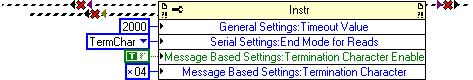
Use these settings
-
Serialize the data into several messages from serial port
Hello
My current LabVIEW project, I want to read data from the serial port and store the (transformed) response in a file.
Since my design model is based arround the Manager of messages queued waiting my serial communication is also build around that. (see this post for my original question).
But now I have the following problem:
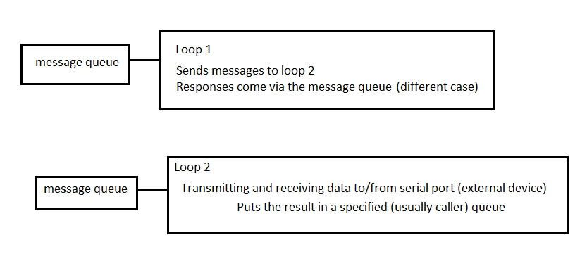
In the loop 1 I put several messages in the queue of loop 2.
Loop 2 processes these messages and sends them to the print queue of loop 1.
Loop 1 gets several messages that need to be combined into 1 string and (with other data) in a file.
Just to clarify:
Loop 1, I have send 3 messages for each connected device. Even though I have a separate file for each device, the response to the messages must be in 1 result string.
(Note on the picture: there are other loops running at the same time you will also need to access the serial port for the port for loop 1 is not an option)
Hope you can help.
A next attempt to download the code
The attached Code is provided as is. It has not been tested or validated as a product for use in a deployed application or system, or for use in dangerous environments. You assume all risk for use of the Code and the use of the Code is subject to the license terms of Sample Code which can be found at: http://ni.com/samplecodelicense
-
Reading and saving data of two serial ports
Hi, I googled similar questions in the forum, but I don't have an answer for my problem so I'm posting it here.
I would read and record data of two balances throgh serial ports. I have a drop down menu in VI, I can choose the availabe ports on my pc. But it is still only one that works. So I only get one data scales them.
I usually get to choose 6 ports, but only one of them works. So I'm wondering if this is something that has to do with my pc or the VI?
I've attached a screenshot of my VI.
Thank you =)
Maybe you are looking for
-
PC is h8 - 1160t, with Intel i7. Graphics card is AMD Radeon HD6670. What is the best way only two as configure/connect installation two monitor?
-
ATV 4 Home sharing not showing upward after 10.11.14 / iTunes 12.3.3
I don't know which update borked... my home iTunes 12.3.3 or El Cap 10.11.14 sharing capabilities. House share used to work before each update. I've tried everything. Does not appear in iTunes, my ATV4 or one of my iDevices. Sharing used to be an opt
-
Re: Buttons on Vista 64-bit of order Satellite A300-1ND multimedia
Hello! My problem is this: I have a laptop Toshiba A300-1ND, and I installed a Windows Vista 64-bit on it. I installed all the drivers from the Toshiba support, including value added package page, which makes the key media work, I think. My problem i
-
"Windows could not complete the installation", Y510P
Hello Just got my new Y510P and realized it's impossible to start Windows. Initially it displays error "Windows cannot parse or process Unattend...» [... \unattend.xml] [oobeSystem] pass... » After reboot he start to display a different message - "Wi