Select the project of the serial port data
Hello world
The project aims to use labview to receive data from a serial port wireless. The serial port will receive two values (X 1 and X 2) every 10 minutes. I want to use these two values as inputs to my formula. How to make the selection? Thank you very much.
Baicy
Scan from a String.
Using the first option and put numbers for zeros so that it shows some kind of significant result.

Tags: NI Software
Similar Questions
-
Sometimes the lost bytes, reading the serial port
Hello!
I'm reading the serial port data (flow rate 57600 baud rate) that works very reliable so that I do not open any other window
or minimize/restore my window of the application during the program is running. Then a byte of incoming data will be lost.
I get a string of 30 bytes each 50 m in most of the cases the first byte is lost, sometimes one in the middle.
This occurs not only on a PC.
Is this a problem of LabVIEW or Windows?
Are there settings that can solve the problem?
Best regards
JK78
I solved the problem.

There was a bug in my program who become visible only if a window has been reduced or restored.
When there are two or more messages in the buffer VISA, the separation of the messages was incorrect.
Array index corresponded to false so that the first byte of the second message was at the end of the first
and so the second message in the buffer seemed incomplete.
In normal operation, the playback loop runs so fast, never both messages are in the buffer.
Thanks for all replies.
JK78
Either way, I work with LabVIEW 2009 and serial interface hardware motherboard. With XON/XOFF flow control
is not possible in my application because all the hex values from 00 h to FFh may appear in a message.
-
How to periodically send various types of data via the Serial Port?
Hello! Everyone
I have to send data to LabVIEW to my device on the Serial Port.
I know how to send data on serial port in LABVIEW, I already have this part.
Now the problem is that I have several types of data I need to question my embedded device, if I want to send the query periodically command.
So lets say that my four Op Codes are the following, which will send four different types of query command to my device on the serial port.
(To be honest only OP_LED and OP_SENSOR is used now)
0, OP_SYNC
1, OP_LED
2, OP_SENSOR
3, OP_FUTURE
Structure of basic package is as follows:
Header (0x2C), Checksum, length of the data (n bytes), Op_Code (1 byte), length (length of Code + data Op)
For OP_LED, I need to send the package as follows:
0x2c 0x02 0x01 0 x 00 0x2F (0x2F being the XOR checksum) (calculation of Checksum part is done and SUB Vi form)
Length of the package this is 0x02
0x01 is Op Code for OP_LED
In the same way
For OP_SENSORi need to send the package as follows:
0x2c 0x03 0x02 0x00 0 x 00 0x2D (0x2D being the XOR checksum) (calculation of Checksum part is done and SUB Vi form)
0x03 is length of packet here
0x02 is Op Code for OP_SENSOR
So, how can I do this periodically in labview, in such sort that period can be adjusted whenever necessary.
Is there something in LabVIEW to do.
I had done the reception and decoding part and working properly.
So I must implement read and write the part of same while loop?
Do not insert in the table if you put data in an array at index 0. Just use array to build.
No need to have Visa to write don't be a part of wire to the wire of reference and error VISA go in the upper part. These wires should go THROUGH the entry VISA.
Don't your checksum requires all the bytes up through data? Righ now, you only put the checksum on data bytes and forget the opcode and length bytes.
Your sending is not the opcode for Opsync or Opfuture. You just send the empty tables. At the same time for the other two, you put the opcode in the data table. All your original opcode in the table build thread. Get the data out of these structures in case item which is supposed to represent the opcode.
xpress_embedo wrote:
Now it works but I have now two problems.
(1) OP_SYNC and OP_FUTURE do not data, but still receive its data on serial port, can I do something here as I have nothing when the table is empty in the structure of the case.
I do not understand this statement. Perhaps my answer above will fix any issue you have here.
(2) how can selection operation Code to be send is done using control façade but real application, this task should be automated to a certain frequency, like OP_LED package must go out to the serial port to 100msec and packet OP_SENSOR must go out to 1000msec, I do this.
Now you agree a little more architecture. I would encapsulate the code that is in the while loop as a Subvi. Then with the hand of your program while loop, use two time Express VI, a game for 100 msec, the other for 1000 msec. When an express VI is true, run the Subvi with a command set waiting for the answer. When the other VI Express is true, have it run the Subvi with the other set of commands.
The device responds with anything when you send these commands? You only send data. I see no VISA Read to be able to recover all the data.
-
Store data from the Serial Port in the buffer and then take action?
Hello! Everyone,
I'm new to LabVIEW and I take assistance from various videos and stuffs available online to get started with LabVIEW.
But I have a duty, therefore needing help.
initially I see some of the tutorial videos and learned about the LabVIEW interface, and does a little project to communicate with the Port series (receiving and sending data).
Happens to my task.
My LabVIEW application will send a few State request packets on my device or control and based on the response packet that I have to display values.
The Structure of package is as
Header, length, Op_Code, data Checksum
There is no terminator as newline or carriage return or anything else.
In C language, I read the data from the Serial Port, and based on the length, I conclude that I got the full package or not, and then by recalculating the checksum value, the integrity of the package is verified and then based on that Op-Code has been sent will be decided.
(I'm dealing with hexadecimal data)
But how can I do this in LabVIEW.
A tutorial or any referece will be useful for me.1. I suggest that you learn to use Shift Registers instead of local and global variables. They are much more efficient (memory and execution speed) and make it much easier to read the schema.
2. you don't need this inside the loop property node. Is there a way to configure a Serial Port to turn off the stop character.
3. you don't need to wait for playback VISA will limit the rate of loop if no data is coming.
4. Once you have the length, you simply read the rest of the entire message and process it at a time. This will make things a LOT faster.
5. you should really do this enum a def type so that you can ensure that all your enum constants have the same values. If you need to add a State later, simply update your enum in the same place then.

-
Using the Serial Port for data acquisition Non-Serial
I searched the forums and can't find anything on this topic.
I saw that it was possible to use the parallel port for e/s digital single and I was hoping that the serial port can be configured the same. It seems all VI VISA only to use the serial port to receive ASCII characters at a given flow rate, but is it possible to simply query the status of the line series at my own speed to see if it is high or low, kind of like a single pin DAQ?
It seems that it would be possible until the serial data are read and controlled by labview, not Windows. Let me know if you have ideas of how to approach this problem, or any comment as to why it is not possible.
Thank you all!
Select the property > settings series > Modem of the line parameters. For example, the State of the CTS is an entry to the pc.
With the help of these lines is a very poor substitute for a scope or map DAQ. The only things you can return is Asserted, Unknown or Unasserted. The range of acceptable signals is important enough. Anything between + 3 and -3 is an unknown state. Your other signals is + / 3 to 15 volts. What type of signals do you really want to capture?
Edit: there is no such thing as a visa so I have no idea of what you actually use.
-
collection of data & graphical CTS (M-24) using the serial port
I work to collect data of a test (M-24) CTS station, using the serial number of the station to the serial port on my laptop.
Looking for information on the vi.
There is no driver for this instrument (I guess you are referring to this: http://www.cincinnati-test.com/sent_m24.php) on IDNET. Therefore, unless someone has already written an and happen to run across this thread, you will need to write one yourself. It is not hard to do, but you will need programming manual. There are a number of resources to help you write one: http://www.ni.com/devzone/idnet/development.htm. Since you intend to make the serial communication, you should also look over this: http://zone.ni.com/devzone/cda/tut/p/id/4370
-
How to read the Serial Arduino data using labview VISA?
Hi =). Im a beginner work reading data series from an arduino but im facing... Lets do it step by step
I built a voltage divider circuit which gives from output
from 0 to 5V. The output of this circuit is sent to a 0 analog input pin
of a Committee of Arduino Duemilanove.(1) Firstly, I connected the cable to connect to my laptop USB the Arduino.
(2) I went to start-> control
Control Panel-> system-> hardware-> Device Manager. Check the Ports (COM
& LPT). In my laptop I can see USB Serial Port (COM4). Now I know only in
LabVIEW that I must read the data series COM 4.(3) to the side of the arduino, here's the code to read changes in voltage
entered to analog pin 0. The last line of 'delay' determines the sampling
Rate of how we want to taste the output of the voltage divider:int potPin = 0; Select the input pin for the output of the voltage divider
int val = 0; variable to store the value from the probevoid setup()
{
Serial.begin(9600) (9600); Opens the serial port, establishes the rate of 9600 bps data
}void loop() {}
Val = analogRead (potPin); read the value of the voltage divider
Serial.println (Val);
Delay (10);
}I slightly modified the basis series reading writing VI... I have
attached the block schema used with comments. Basically, I tried to read
data series, divide by 1023 and multiply by 5 to graphic voltage
variations of the voltage divider circuit. But Im not getting
the correct voltage output values. The value of the tension just keeps go
0 and coming again, as shown in the photo.Could you guys please guide me on what went wrong?
Thank you!
-you read the data, even if there is no data on the port. If 0 bytes are read => «»
-in the case of false, you resources VISA wired for the output of channel tunnel?
-There is no close VISA at the end of the VI resources
-you're not a loop this VI reading bytes
I added an addaption of your VI that you should give a try maybe

-
Using the Serial Port on the HP 50 g graphic calculator
Hello world
I have another question. I want to use the Serial Port on the HP 50 g to connect with another device. The device is called the MFJ-1214PC. What it does is to accept the text and commands through a 9-pin serial Port and converts the text in a Code Morse/RTTY sound audible. It also decodes Audible the Morse Code and RTTY radio signals and displays them as text on your computer. The program that controls the MFJ-1214PC was originally written for an IBM PC for the MS-DOS operating system. The HP 50 g graphic calculator meets the system requirements for the simplest version of the program. I was wondering if there is an MS-DOS emulator written for the HP 50 g, which would allow the HP 50 g to become the computer in this case, or if the program could be rewritten and brought to the HP 50 g. If it could be rewritten, programming language what do you think would be better suited to this type of application (if it is even possible?) or UserRPL, SystemRPL or Assembly. Don't forget that I'm a complete newbie with the HP50g and have never programmed with it yet. I'll include the manual of the MFJ-1214 PC as an attachment so that you won't have to look for him. Thank you in advance for your help!
~ Zekelegge ~.
I understand (from my brief overview) out of the box-MFJ-1214PC, this offer box decoder output series computer. The computer (50g in your case) will have the software to read message series and then convert that to an output for display.
BartDb gave you the right answer.
A serial cable with the correct speed level and reversing lever to manage as well as the 50G has a RS-232 signal to the outside world is the ideal solution.
However, make sure that the output of the decoder box series package can be understood by the 50 g. aud, bits, etc. (you have the set-top box manual, so you'll have to look that up)
the streamsmart is not an aggregator of serial port.
in other words, these connectors DIN of Qty 4 on the front do not accept series rs-232 input and send then to 50 G.
I'm not an expert, streamsmart more info on these boxes is rare to find. The probes are even more rare.
However, I know that the 4 connectors are for the analog-to-digital conversion in the probes. The streamsmart works as a "data logger" in which he sees the input probe, the A/D converted, then sends it to the 50G (or a computer via the USB port).
In addition to the solution of Bart, there was another named Tiwag forum poster who created a serial cable and displayed a schematic representation of the cable. This information can be found here:
to see an example of programming to use the serial port of 50G, you can reference the following hpcalc GPS data collection program.
http://www.HPCalc.org/details.php?id=7105
It is written in userrpl so can be crossed with the reference of users advanced for the translation of the syntax.
It seems that the main routine of concern for the comm to the gps is in the file "GPS >.
-
Can not read the serial port VISA without MAX
Hello
I'm trying to build an application that will interface with a Black Cat Systems GM-10 radiation detector.
The app works fine on my computer (with the full development system OR) but when I install it on another computer, without LabView, the application cannot see the serial port!
I checked that the driver is installed correctl and Windows can see the device, but when I run my program, he can't seem to access the serial ports.
I then tried to install MAX on the second computer, how the application worked well, but as I install this app in other places, I don't really have the ability to install MAX everywhere (software must be autonomous).
Any help would be appreciated!
Z
I would have joined the project file, but the forums seem to not want to allow me to download that big of a file.
What version of LabVIEW are you using? With 8.x, the installer is very able to install the runtime of NI-VISA and MAX. If you are using an older version of LabVIEW, there is an option to include the series VISA support. Install just MAX will do nothing to make the available ports. This is the VISA that does this.
-
level of tension for the serial port sbRIO
What are the levels of RS - 232 votage on sbRIO serial ports? Signal levels might be: 3.3 V, ± 5 V, ± 10 V, ±12 V and ± 15 V? ±12 v what I often see for a direct connection to the serial port of a PC.
Hi Matthew,
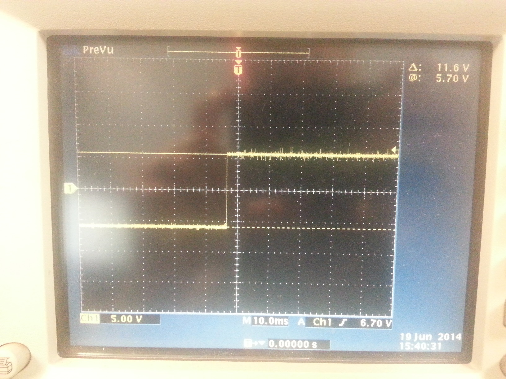
The signal levels to the sbRIO-9605/06/23/26/33/36 are ±5V. I took a quick screenshot of TX W.R.T. GND. Tensions in the data sheet the standard ±5.4V (typical) loading with 3 k and a minum of ±5.0V. The RS-232 standard can accept a pretty big swing however (-3V to-25V) and (+ 3V to + 25V) for two levels of logic. The screen was shot I took with a unloadeed line so the voltage levels appear to be higher than most.
The transceiver set used is the MAX3243.
-
The VI "VISA set up the Serial Port" will only work at 9600 baud
I wrote a Serial Port RS232 RW.vi monitor of ' "which works for most. The problem is that it will not meet the alternative port configuration settings... For example: the default RS232 serial port configuration is:
(COM1, 9600 baud, 8 data bits, 1 stop bit, no without parity)
As a test, I use a Null Modem cable to connect to my LabView Com1 port to another PC running RealTerm Serial Port Monitor... Using my "RW.vi RS232' newly designed with the port settings of (COM1, 9600 baud, 8 data bits, 1 stop bit, no without parity), I can send and cannot receive data back throughout the day no problem...
However, if I configure the port "RW.vi RS232" all other configurations, such as (COM1, 2400 baud, 7 data, 1 stop bit, odd parity bits)... He will not take the expected risks and continues to operate @ 9600 baud rate etc.
Then, I changed the settings default "RS232 RW.vi" (2400,7,1, Odd)
He still refuses to derogate (COM1, 9600,8,1, no...)
I also went in the Device Manager of Win XP on the system of LabView and configured manually Com1 2400,7,1, Odd
and yet,... work at the "RS232 RW.vi" @ 9600,8,1, none
Everyone can test my VI in the car and see if they have the same problem of not being able to see the new changes in the Port configuration settings... other than (COM1, 9600,8,1, no...)...?
FYI... Unfortunately my LabView runs on Version 6.0, you may need to up-conversion of the attached vi
Instead of simply appreciate the comments, you need to implement.
Having closed VISA inside the loop is definitely the problem. And Crossrulz is 100% correct about the problem being that the serial port gets zero to default baud rate after the closure of the port. Here's the proof.

Note that while may have set the port settings manually in the Device Manager, these parameters are reviewed by the pilot VISA. If you look in the measurement and Automation Explorer under devices and Interfaces > serial and Parallel, you'll see the default settings using the VISA driver. If you change this setting, your program will work as desired. But this is not the appropriate fix. The correct solution is to get the VISA close out of the while loop.
The port settings are established in this order.
1. by Windows device drivers.
2. by the VISA driver as set in MAX. Since you are using VISA, these settings will be automatically replace #1.
3. by the port settings, you set programmatically in your LabVIEW program.
-
Read the Serial Port in case of break in series
Hello world
I want to create a VI who will write a series, write interruption, then wait for an interrupt series to be received and if it is received, read what's on the serial port. However I can't the VI to detect that an interruption of the series took place. I looked at and followed what was done in the "Detect the Event.vi Break" example in examples of Labview. The microphone that speaks to the VI sends a break of 13 bits (approximately length 57us), as expected, proved by the use of an oscilloscope but Labview is not contagious. I have attached the VI in question. It is used as a subvi in a larger program. I'm missing something or doing something wrong?
I do not know. 230 400 is a very fast pace. The UART in the PC isn't really in the game, but the EasySync USB/serial box is what is the factor. USB is part of the communication may be adding a few complications. You may browse the EasySync detailed technical data to see if they talk about it.
I would certainly try a very long break first. If it works, then start working backwards to small jumps. If a long pause does not work, then you know that perhaps the problem is elsewhere.
-
How use the serial port read and display the text but not scroll off the screen?
I'm new-ish/return user fan of Labview and trying to change the example VI "Advanced serial write and read VI" is the part of the dev suite 2012. I need to use the string box for ALL of the text from a serial port, always adding and just roll off the screen when the actuals come to the serial port.
What actually arrived more than bytes (or no bytes AT ALL!), during reading time text, current rolls out of the box in the chain. Even when receiving 0 bytes, screen is removed. I'm not very familiar with the locations of functions and even worse to understand obscure references to functions, so please keep very basic answers so I can follow.
Just to be clear, I need window of the chain behave as HyperTerminal does always displays the data and it is not pushed by window arbitrarily.
Thank you
Steve
A long shot.
Is that what you want?
-
How to set the number of packages to be send per second on the serial port in labview
Hello.
I need to send data to the serial port such that each data packet must be sent at a rate of 4 packets per second? How can it be done?
Thanks and greetings
What defines a package?
You just need to have a while loop with a timer waiting for 250 milliseconds surrounding your VISA writing the function.
-
read the serial port management using the SRM Protocol
Hello
I have a gas analyzer that communicates with the PC via the serial port.
This is the "Industrial VarioPlus SRM".
I have attached a PDF file that describes the communication protocol.
I'm trying to decode the data that are sent from the parser, but I can't do it.
I have attached the vi in which I made some effort.
Any help is appreciated, at least for a single value in the data stream.
Thank you.
Maybe you are looking for
-
How to connect the TV to Satellite L300-209?
Hello I have laptop Satellite L300 Searies-209 and I need to connect the LCD Sony TV The Outbut is inbut HDMI and VGAWhen I connect the wire nothing happen in the LCD TV If anyone can help me please help me in this problem
-
Decimate an array of meaningful size to 1 GB of data and apply the filter
Hey guys,. So I used a high-precision laser Interferometer to collect data to frequencing 10 MHz, which will lead to a 1 GB of raw data files. I converted this position given to speed for parsing data. But I still have a file of 1 GB with billions of
-
Impossible to rebuild the boot.ini
I have a computer infected by the virus from system tools. I was about to make the procedure of McAfee to clean off when I met the msg of bad boot.ini with: \system32\hall.dll I see that this is a problem common - and followed the instructions to sta
-
100% CPU usage when playing online.
Original title: 100% CPU utilization CPU USAGE XP MEDIA CENTER SP3 100% WHEN ONLINE GAMES IS NORMAL ALSO PC STARTS TO MAKE BIG NOISE. SWEET STARS CAN GET REALLY LOUD
-
Blocked (or almost) to "Press the ESC key for Startup Menu" - hardware error!
Hello My daughter has a laptop HP 625 (product code WS786EA #AKS, windows 7) is no longer starts. I tried a lot but have now run out of ideas on how to fix it (or see what error) When I power on, it is blocked for a long time on the HP logo screen, s