Shunt Cal 9237 operation
Hello
I'm looking to make a cal with the 9237 derivation. I built a simple FPGA vi which seems to work - I can change the sampling rate and perform a cal lag. However, when I activate the shunt cal switch, the output doesn't does not change. I noticed in the stitching of the SC Schematic of wiring. I connect these somehow? (No explanation is given as to what they mean I see). My understanding is that the 100 k ohms resistor internal to the Board of Directors and I did not connect anything to the outside.
Any ideas?
Thank you!
Hello
Wayne.C is right about the SC to connect to your sensor. Below, I have provided a link to the specification document NI 9237, references, page 10 (figure 3).
http://www.NI.com/PDF/manuals/374186e.PDF
-Jake B.
Tags: NI Hardware
Similar Questions
-
Access 9236 shunt cal with scanning mode?
How allow us calibration shunt with scanning on the module 9236 quarter bridge strain gasoline
We are very happy with the release of Labview 2009 and RIO 3.2 because most of the cRIO modules now supported the scan mode.
We want to use the interface in scan mode with the quarter bridge strain Guage 9236 module, but we must be able to access the features of Shunt calibration. With the FPGA interface, you acquire a set of data. Then allow you the shunt calibration and gain a second set of data. Then you compare the two to get to a scalar value using some equations. This eliminates lead resistance in your calculations, which can be less than ignorable in certain circumstances.
Thank you
It was easy. I just hung out and left down the constant IO then right mouse clicked on it and all its I/O write properties come. Very cool. All too easy to be crio programming, lol.
-
load cell 9237 + full-bridge: load cell_null_off_shuntcal.vi - error 200077
I try to use load_cell_null_off_shuntcal.vi with load cell (Honeywell model 31, not amplified). I'm using LabView 8.6, cDAQ-9172 and NI9237. Entries: excitation10V internal; mV/V 2.1492 (calib. bin); weight 10 lbs max. resistance bridge 350 ohms (Honeywell specifications); 9237 internal shunt resistance 100 kohm; map of shunt R4 (default setting). Selected "offset null" and "shunt cal.
Error-200077 occurred to Shunt calibration perform DAQmx
. VI:1 (bridge) or the possible reasons:Measurements: Requested value is not a supported value for
This property.Property: I. Bridge.ShuntCal.GainAdjust
You asked:-61.980405e3
Valid values begin with: 500.0e - 3
Valid values ending with: 1.500000
If "shunt cal' green button not selected, no error. Setting the gain should be about 1. Subvi DAQmx PerformShuntCalibration (bridge) .vi contains "Call library function node" which is locked (?).
Any ideas?
What is the location of item correct shunt for a full-bridge load cell? Change this location does not eliminate the error.
Hello, YTC,.
The problem is most likely in your external connections of the NI 9237 and the load cell. As mentioned in NI 9237 Operating Instructions and specifications, page 9, SC + SC - pins must be connected to the terminals of the resistance specified in the .vi of Shunt calibration perform DAQmx (bridge) (in the case of a full bridge, it would be R3).
Let me know if you still have problems with your calibration.
-
9237 with deck full load cell: support cell_null_off_shuntcal.vi survey error 200077
Normal
0fake
fake
fakeEN-US
X NONE
X NONE/ * Style definitions * /.
table. MsoNormalTable
{mso-style-name: "Table Normal";}
MSO-knew-rowband-size: 0;
MSO-knew-colband-size: 0;
MSO-style - noshow:yes;
MSO-style-priority: 99;
MSO-style - qformat:yes;
"mso-style-parent:" ";" "
MSO-padding-alt: 0 cm 0 cm 5.4pt 5.4pt;
MSO-para-margin-top: 0 cm;
MSO-para-margin-right: 0 cm;
MSO-para-margin-bottom: 10.0pt;
MSO-para-margin-left: 0 cm;
line-height: 115%;
MSO-pagination: widow-orphan;
font-size: 11.0pt;
font family: 'Calibri', 'sans-serif ';
MSO-ascii-font-family: Calibri;
MSO-ascii-theme-make: minor-latin;
MSO-hansi-font-family: Calibri;
MSO-hansi-theme-make: minor-latin ;}Hello
I'm trying to use the example
load_cell_null_off_shuntcal.VI with a scale of full-bridge (Honeywell
Model 31, not amplified). I'm using LabView 8.6, cDAQ-9172 and NI9237. The
load cell is connected to the pins 2,3,6 and 7.Entries for the front side of the VI
are: excitation10V internal; mV/V 2.1492 (calibration sheet); weight max 10
lbs; resistance bridge 350 ohms (Honeywell specifications); 9237 shunt internal
100 kohm resistance; map of shunt R4 (default setting). I chose
"Do not offset null" and "shunt cal.This is the error I get:
Error-200077 occurred at DAQmx
Do a calibration Shunt (bridge) .vi:1 or the possible reasons:Measurements: Requested value is not
support for this property value.Property:
AI. Bridge.ShuntCal.GainAdjustYou asked:-61.980405e3
Valid values begin with: 500.0e - 3
Valid values ending with: 1.500000
If the "shunt cal.
green button is not selected, there is no error. I understand that the Gain
Change value should be approximately 1, whereas I get is much larger. The Subvi DAQmx PerformShuntCalibration
.VI (bridge) contains a "Call library function node" which I did not
find out how interrogate.Someone else has experience
with this error? Do you have any advice on:1)
How to 'see' the calculations being
carried out inside the "call library function node"?2)
What the correct shunt element
a full-bridge load cell location is? (although changing this location only)
does not eliminate the error, I can't find this info).3)
What can I do wrong with
my entries to cause this error?Thank you
Claire.
Hi Claire,
You must physically connect the SC of arm of the bridge terminals (normally R3). The terminal is not provided for the connection of external resistors.
See the example
C:\Program NIUninstaller Instruments\LabVIEW 8.6\examples\DAQmx\Analog In\Measure Strain.llb\Cont Acq strain samples (with calibration) - OR 9237.vi
-
Calibration shunt 9235 with 9144 in Scan Mode
Hey everybody,
I use two 9144 s and a 9074 and I am trying to create a routine calibration of shunt for 12 9235 s (4 per chassis). I found this article on how to shunt calibration with the 9144 and a 9237, but it does not work:
http://digital.NI.com/public.nsf/allkb/12017868777480AE862579BA004F0877
This is the error I get:
Error 65723 appeared to node (arg 1) property in the Shunt Cal 9235's.vi
Possible reasons:
CompactRIO: This module cannot be configured when the engine of the controller is in its current mode.The thing I don't understand is that the modules on the 9074 calibrate correctly, but when I try to calibrate a channel on one of the 9144 s, I get this error. I couldn't find much about this error, I was wondering if someone could help me and point me in the right direction.
I have attached my code. It is relatively simple, and I don't see where the problem would be. I have to manually set the mode of the 9144 something than what it is currently (i.e. Active configuration)?
Thank you for your help,
Seth
Your system may start in Active mode by default. This mode does not allow to set the properties of your ECAT 9144 chassis. the chassis must be in configuration mode to enable the derivation property. See attached changed VI.
DirkW
-
calibration of strain using Signal Express measurers
Hello
The first time asked. Thanks in advance.
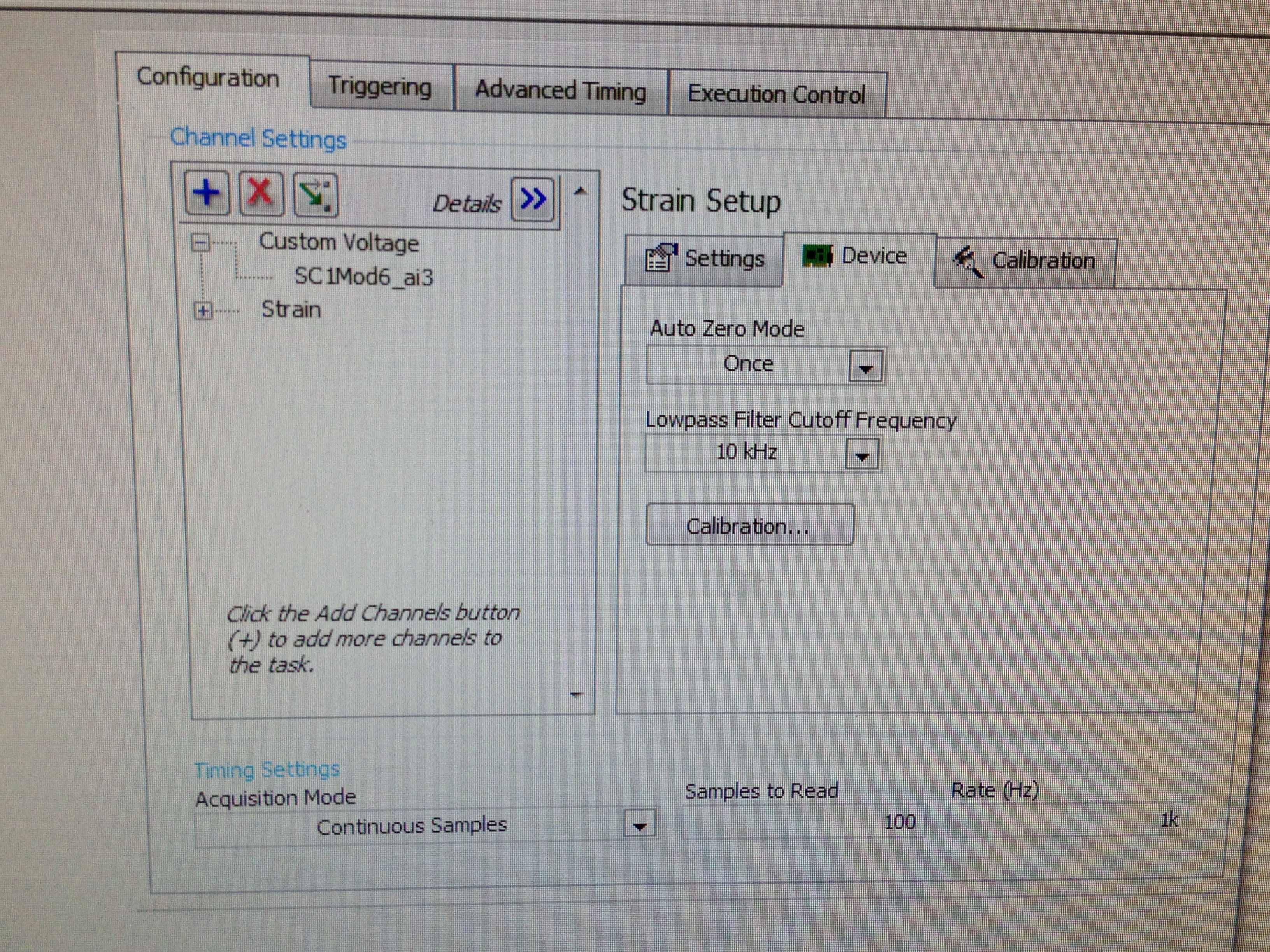
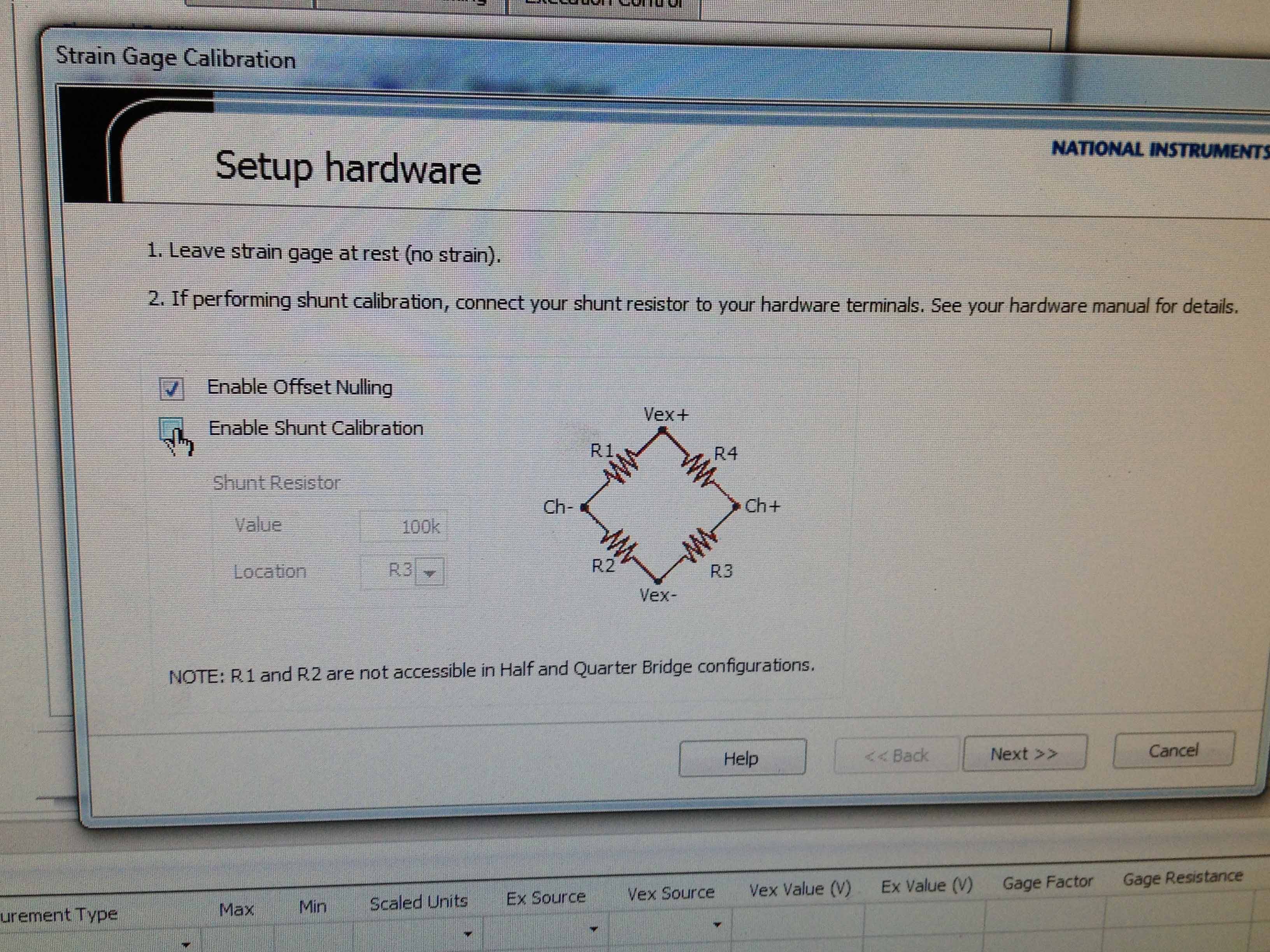
I use NI DA system to record the strain of a strain gauge 1/4 350 odm. The connection string would be extensometer---> SCXI-1314 (Terminal)---> SCI 1520 (block 2). I connected the cable to the S - P + and PIN the SCI QTR 1314. The value of the strain appear in LABVIEW EXPRESS. Now, I need to calibrate the extensometer (OFFSET REMOVAL and CALIBRATION of SHUNT). I'm stuck... I have two specific questions:
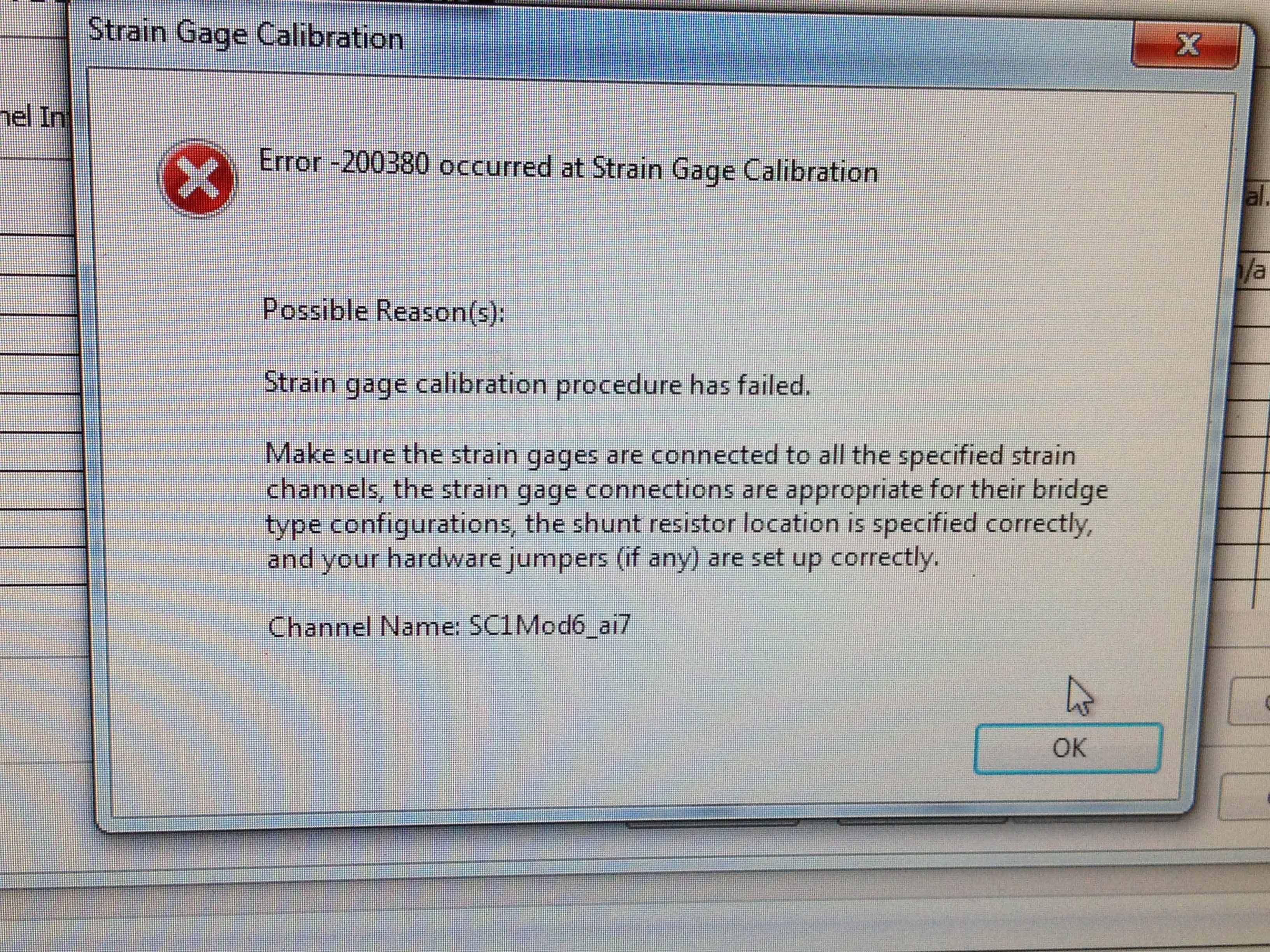
1. when I just check 'Offset the removal' in 'calibration' tab error-200380 orrcurs. Can you guys help out me?
2. I noticed that there are specific pins for the SCXI-1314 shunt calibration. If I wanted to shunt calibration, must I change my wiring, so that the resistance of odm 100 k can be included in the circuit?
Thank you very much.
In your first post, you have the cable signal since the pledge is going to S- My first suggestion is to move your thread to signal S - s + if you don't have it already done. When 1/4 hanging bridge you only have access to R3 and R4 which are on the + next to the bridge. This high an error on your gain stage is usually a wiring problem or you maneuver the arm hurt in the bridge. In the calibration Assistant spend R4 R3 and see what happens.
How connected your pledge?
Of your pledge, you should have 3 wires. Vex + (red) on a tab of the pledge and shunt cal and GIS (tied together) on the other tab of the gauge. See my attachment to a vision of how I wired my system. Other colors, the screenshot of your wiring diagram looks like it should work. The difference being, ma sig + is green and the shunt is brown; where your of seems to be white and black. Anyway, double check your pledge and make sure that leads back to your terminal block are where they should be. In the 1314 default shunt resistors are all 100 kilohms unless something has changed in your system, you should be fine.
You can attach a copy of the file .seproj or tab 'Settings' from your screenshot strain gage configuration window. Things like factor value excitement and resistance will affect your calibration and output.
-
Frequency counter measurement crashes when you're away point zero (NI USB 6343, error-200284)
Members of the Forum,
I have problems with a measure of the frequency on a DAQ Mulitfunction of NI USB 6343 X series. I use the meter 1 (door axis for frequency signal, PIN to DGND 82 77). The couple HBM T10F flange that I use (powered by a power supply of 24V) emits a signal of frequency between 5000 and 15000Hz with 10000Hz being the zero point. Couple flange has a capacity of 5kN.m (15000Hz = 5kN.m; 5000Hz = - 5kN.m).
I have been using the VI attached for a few months now without any problems. Now, the VI works fine as long as the couple remains inside a few hundred Hz of the zero point. However, when the frequency increases further reading couple begins to freeze and finally I get either of these two errors:-200279 or-200284 related samples is not not available. I noticed that the light on data acquisition close compromise during these periods of frost.
Here is an example step by step my problem using cal shunt of the flange of the couple:
1. I have run the VI and couple bed properly around 10000HZ (Active light, indicator light ON)
2. I have apply the excitation of 5V to the shunt cal and frequency climbs to about 50% of the ability to couple brackets (as it should)
3. as soon as I remove the excitement 5V playback freezes and the light on the acquisition of data.
4 if I apply the 5V once again, until the timeput occurs, the led turns on and the acquisition of data reads the signal correctly.
This type of problem would be more DAQ-related or is it the flange of the couple itself.
Thanks in advance,
Mike
Solved.
I did some troubleshooting this morning and it turns out that the vibrations of the system had not tightened a screw that was connector to the stator flange torque causing a bad electric signal of the torque flange itself.
Everything works fine again.
-MB
-
Hello world
According to the statement, NOR for the verification of the Pxi4330 procedure, I need "Disable calibration shunt for the channel by using the property node DAQmx Channel, you can find custom I/O" DAQmx - data palette purchase LabVIEW. "'" ' Select the analog input"General properties" conditioning of signals ' bridge ' Shunt Cal "activate property of Shunt Cal. "but I can't select this property that I want to say there is no property such as?
What is everyone knows what the problem is? I lost 3 hours to solve this stupid problem, still can not find it.
When I choose the General Properties property, analog, node there are two options that are not the answer.
Please help me on this
Thank you
Hi Eric,.
You have an SMU-4330 installed on your system? There are MANY properties of different devices, and to avoid confusion of the properties that do not apply to you, DAQmx tries to hide the properties that are not applicable to all devices in your system. If you don't have an installed SMU-4330 (or a simulation of SMU-4330), then the property you are looking for appear by default. To find it, you have two options:
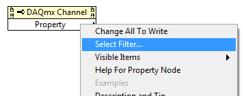
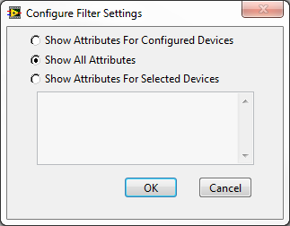
Option 1: turn off the property node filtered by right-clicking on the channel property node, by choosing "Select filter...". "and then selecting"display all the attributes:
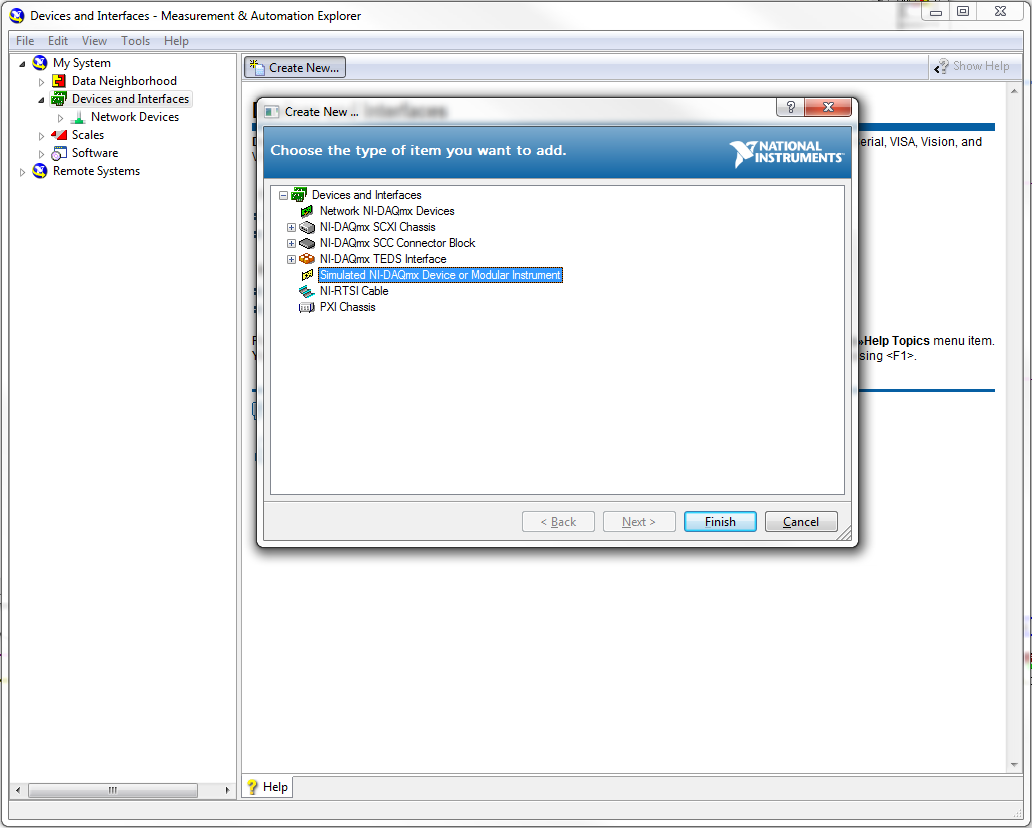
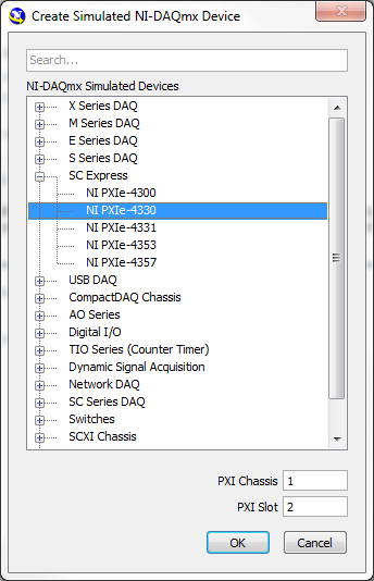
or Option 2: install a real SMU-4330 or simulated in your system. You can install a device simulated through the program of Measurement & Automation Explorer (MAX):
-
"Bridge shun cal.vi" shunted the setting of the value?
I copied the "bridge shun cal.vi" LabView example "Acq gauges bridge samples (with calibration) .vi", to include in a strain measuring .vi I'm working.
My equipment consists of an SCXI-1001 chassis, modules of 1520 and 1314.
That means the acronym for setting the value of "Shunted"? Resistance value of triage (in ohms, I supouse)?
And it's less important to me, but think it may be interesting for others: how to choose between the calibration shunt resistance is or B?
Thank you
usuario
Hi user,.
You are right when you say 'shunt resistance' in VI stands "DAQmx perform Shunt calibration (bridge)" for the value of shunt in ohm resistance. As you can see on page 4 of the SCXI-1314 manual, the two shunt calibration resistors A and B are have a value of 100 kohm. In addition, page 4-28 the SCXI-1520 user manual specifies that they are are in style RN-55 (standard 1/4 W).
Choosing to respect so shunt calibration resistance A or B, the latter manual mentions on page 3-4 that "shunt calibration switches A and B are parameters of control of software that allow or activate or deactivate the shunt calibration resistors in order to form win calibration." In most cases, you do not explicitly switches shunt calibration check, he makes instead of software driver to automatically adjust them for you during the shunt calibration procedure automated. However, if you want to explicitly control the witches of calibration, you can write an application program which controls the shunt calibration switches.' and returns the user to Chapter 4, principle of operation, for more information.
I hope this helps.
Kind regards
-
need to know if the NI 9237 - no compenstation such temperature on bridges and shunt calibration
need to know if the NI 9237 - no compenstation such temperature on bridges, also, I need to know if she calibration shunt.
Hey invzbl_rkl,
The NI 9237 - can do both remote sensing and Shunt calibration. You can see the details on how to connect the bridge in the USB-9237 user guide and more details about compensation in the article attached Developer Zone on measurement of strain.
Specifications and NI USB-9237 User Guide
http://digital.NI.com/manuals.nsf/WebSearch/B218E7E6DDB1D4518625738600784930Strain with gauges
http://zone.NI.com/DevZone/CDA/tut/p/ID/3642 -
Original title: Software Assurance
We have the assurance of software on the operating system server & CALs client server. Our agreement expires in June 2013. Do we need to exercise our upgrade to the licenses before 2012 June?
Hello
Thanks for asking this question to Microsoft Community.
I suggest you check the Microsoft Software Assurance Web site for assistance.
http://www.Microsoft.com/licensing/software-assurance/default.aspx
Software Assurance FAQ:
http://www.Microsoft.com/licensing/software-assurance/FAQ.aspxIn addition, you can contact support by calling team: 800-936-3500.
Hope this information helps.
-
Calendar Server responds with 403 Forbidden' operation CalDAVWriteEntityQueueableOperation.
With the latest version of Mac server (5.1.5 on OS X 10.11.6), when I try to migrate a large calendar via a client computer, it takes a long time and then I get an endless series of
The server responds with an error.
Access to the "[name of the cal event]' in '[the calendar name]' account"[account name]"is not allowed.
The server responded:
"HTTP/1.1 403 Forbidden.
operating CalDAVWriteEntityQueueableOperation.
[Go offline] [Back to the server.
errors. I have to leave something heavy press enter for a few hours to get rid of all the errors.
Migration of the small calendars to the server (by importing data in iCal on the calendar of the hosted account) works for most (it may be a mistake or 2).
I found a suggestion of years ago on another Board that permissions can be screwed to the top and use this Terminal command:
sudo chown-r _calendar:_calendar/Library/CalendarServer/Documents
However, this suggestion was for the 10.6 Server and may no longer apply.
Any thoughts?
Today, I had the idea of trying to download the calendar from the same computer that is serving the calendars. Should be faster and better (and the same OS!)!
So, an account on it hosting Mac and started the import process, which seemed to go more smoothly, but then seemed the same thing happening: most of the CPU has been get taken up with various activities related to the calendar and then after a while, it started spitting out errors, but they were slightly different. There are too many mistakes all move just above. Also, try to add more events to this calendar also fails.
Now, they say:
The event "[name of event]" was rejected by '[Server]' because the maximum number of resources has been reached.
Is there a limit to the size if a calendar?
I do something wrong or is this a limit of the software?
-
Wavy jagged singal of 9237 at no load condition
Dear forum users and employees of OR,.
I would be grateful to you if you can solve my problem. My specimen is a simple piece of plastic 1 0.25 inch rectangular cross section with a length of 8 inches. I'm trying to measure the deformation (with the help of use general TML, Japan 1 mm gage length extensometer) in the sample by hanging dead in the sample weights. I am able to strain using the cDAQ 9178 chassis, NI 9237 module with accessory NI 9944 quarter bridge. For a given weight (so the applied load becomes a static), signal (output voltage) must remain constant independent of time. In addition, I also expect that when no load is present on the sample, the acquisition system data above should show constant, but the deformation of almost zero output over time. What is my problem only after offset removal and shunt calibrated correctly with the help of the wizard of LABView DAQ, the above data acquisition system shows a strain of output wavy stair of significant variation between maximum and minimum, even when the sample is at no load condition (the sample is simply placed on the table). In addition, even after loading the sample with a certain amount of dead weight, rather than get a constant signal, I always get a strain of output wavy stair (with more scale position zero load) over time. Please help me get a constant output signal for the data acquisition system above with and without load on the sample.
Thanking you
KSRKM
-
NEITHER 9237 quarter bridge absolute accuracy
Given a NI 9237 bridge completion Module with NI 9944 accessory Terminal strain gauges and 120 ohms with GF = 2.11, how calculate we precision of strain?
I was told that the absolute accuracy for bridges of quarter is given by
Absolute accuracy = (Gain error * reading) + (error offset * range) + noise + half bridge watchkeeping tolerance tolerance.
Since I'm on the NI 9944, watchkeeping tolerance would be 500 uV/V (given by OR R & D). The tolerance of half bridge is given in the manual OR 9237 being 1.2 mV/V.
(1) it has no value of 'Noise' of entry for bridges on watch in the NI 9237 manual; We use only the sound of half-bridge?
(2) if I use a sample rate of 1,613 kech. / s (the rate guaranteed valid sampling for the NI 9237 module) and my system is always in his 1st year of use, always is my gain error 0.05%? It is worth noting that 0.05% applies to the 50 kech. / s ; If the gain error does not apply to my low sampling frequency, how can I find the error of gain?
(3) if my maximum/minimum deformation measures around 600 EU (microstrains), how can I change my values "Reading" and "Range" in the equation for absolute accuracy above, if they need to be adjusted?
(4) why the absolute accuracy for a quarter-bridge set up does not include the half bridge tolerance?
(5) is the equation for the conversion of precision of voltage precision for quarter of a bridge, of the strain
 , where U is the precision of the voltage given by the equation of absolute accuracy above.
Example of calculation using the values assumed for quarter-bridge:
Error error/gain Offset = 0.05%
Reading distance / = 25 mV/V
Half bridge noise = 1.6 mV/V * 3
Half bridge tolerance = 1.2 mV/V
Tolerance of watchkeeping = 500 uV/V
Absolute accuracy = (V/V 0.0005*.025) + (0.0005*.025 V/V) + ((1.6e-6) * 3 V/V) + (1.2e - 3 V/V) + (500-6 V/V) = 25 mV/V +/-1.73 mV/V
Accuracy of the strain =-4(V/Vex) / GF (1 + 4 (V/Vex)) = - 4 * (25 mV/V +/-1.73 mV/V) / (2.11) * (1 + 4 * (25 mV/V +/-1.73 mV/V))
How to simplify this precision of strain to get a reading + / range of precision?
Thanks for any help.
(2) if I use a sample rate of 1,613 kech. / s (the rate guaranteed valid sampling for the NI 9237 module) and my system is always in his 1st year of use, always is my gain error 0.05%? It is worth noting that 0.05% applies to the 50 kech. / s ; If the gain error does not apply to my low sampling frequency, how can I find the error of gain?
This applies at a rate of 50 kech. / s. lower data rate can have up to 0.20% gain additional error reading. This can be found on page 24 the unit operating instructions and specifications document
You get to know how to calculate what percentage of Reading (Gain error) I'd get according to what sampling frequency use? Otherwise, I guess I could use the error of gain of 0.20% in the worst case scenario.
Yes, I so calculate the error of Gain for the worst case scenario (0.2%)
(5) is the equation for the conversion of precision of voltage precision for quarter of a bridge, of the strain
, where U is the precision of the voltage given by the equation of absolute accuracy above.Yes, I think it's the correct equation.
It is more a matter of math - since you will be in the form of a reading + / a range (for example 25 mV/V +/-1.73 mV/V), do you know how I simplify or interpret the accuracy of strain after its replacement by the U-value?
Accuracy of the strain =-4(V/Vex) / GF (1 + 4 (V/Vex)) = - 4 * (25 mV/V +/-1.73 mV/V) / (2.11) * (1 + 4 * (25 mV/V +/-1.73 mV/V))
Just reuse the worst cases to calculate positive and negative values on 1.73mV.
-
With the help of a shunt in 3, 3V application milliohm resistance.
I'm measuring low currents in an application by using a USB6009 wireless sensors.
I expect in normal operation of the device-2uA and successfully measured on the lower part of the appliance with a 250 Ohm resistor.
It was with a USB6008. Now, we would like to use a calibrated shunt standard (.001ohm) and a USB6009 to get data more closely the case of actual use being able to see
150 - 350 ms transitions of the circuit detector field cycling on and outside (necessary to the higher sampling frequency) and we hope to see real activity not to have several millaohm draw to a 250 ohm shunt.
The noise of the 6009 certainly .5mv in the 1V range. I thought, (perhaps wrongly) I could accurately see microvolt voltage level data with a system of differential.
First of all, maybe, that's my problem. My experiement is below.
I have a resistance level of shunt.001 http://www.rc-electronics-usa.com/current-shunt.html ohm (series)
In my first experiement, I had the device (powered by 3, 3V CR232) with the current shunt close the low side of the battery, terminals attached to AL0(+-)
The dynamic range of the measurement was set at 800nA to 10uA
I then see millavolt noise on the weather of the line that the shunt is not connected or not, basically no data.
I then tried with 1.5Kohm resistance pulling on lines AL0(+-) to a GND contact on the 6009. Same result.
Then, I took a laboratory known to 5V power supply and attached a resistance in series with the shunt 1.5Kohm. AL0(+-) through the shunt.
I figured I'd see 3.33... AU on shunt in this configuration, but the saw just le.300 mV ripple on the line which is a much higher current than it should be.
Recommendations on the conduct of these small current measruments? I think buying a TI SOIC or someone might be a good solution / or just a simple old op amp for this tension.
I know that there are amps op there specifically for the current shunts. I'm sure that TI has good as well as Analog Devices.
Maybe you are looking for
-
Question of ground Multi of thermocouple
I have a Keithley 2750 with 7708 card in the first slot. I have no problem getting the readings, but when they arrive, I want to index them based on their channel, which theoretically should be using 0 and 1 with the index command. If this is not pos
-
File name includes one or more invalid characters.
'File name includes one or more invalid characters.
-
How to restore items that you have deleted from the Recycle Bin
I accidentally deleted permanently items in my basket that I NEED to recover, how to make their return for free?
-
Foglight APM - how to create a rule on the parser to hit the base?
I was creating a couple struck analyzers with certain criteria. What should I do when the relevant criteria of Hit parser to appear alarm Foglight. I found the question: http://en.community.dell.com/techcenter/performance-monitoring/foglight-apm/u c
-
Feed READER on BlackBerry Playbook
Hello, I am developing an application that includes an an RSS news reader, I would like to know if you know an example that works on the BlackBerry Playbook. Thank you very much!