Simple PID regulation
Hello
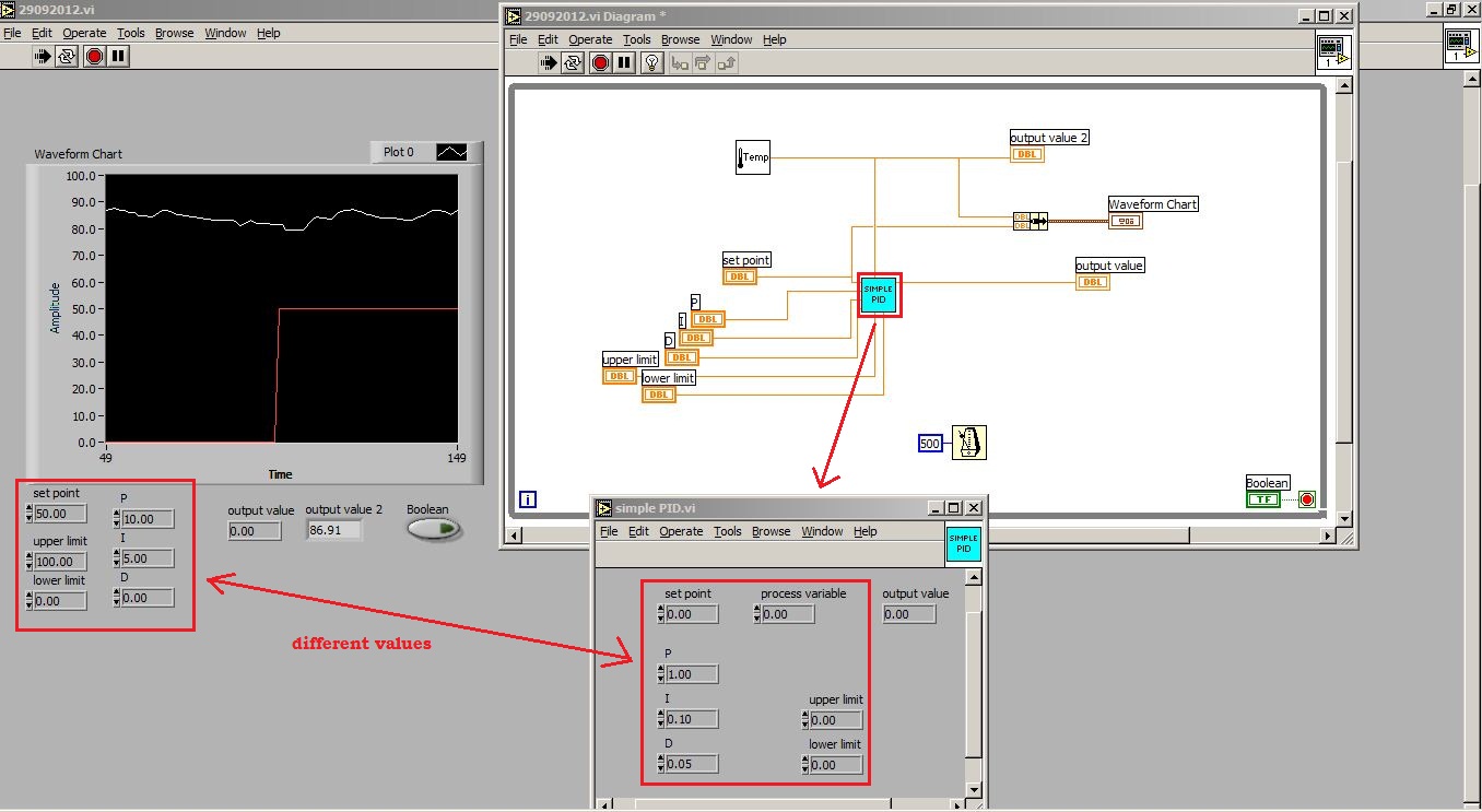
I use an old version of LV, LV 6i to be exact. Now I'm building a control temperature for simple PID control of a room. I use as my NI PCI-6024E data acquisition card. But, in the middle of trying to get the right program, I stuck to the PID regulation. I use the .vi "simplePID" and connect everything that is necessary, the limits of high and low, the parameters (P, I and D), set point, take Subvi 'Temp'.vi, and connect to the variable process and exit the .vi 'simplePID' to a chart.
The problems occurred when I run the application, the temperature did give lectures as usual and I set the setpoint and limits and also settings. But it seems that the "simplePID".vi don't not responds to these values. As the program is running, I clicked on the "simplePID".vi and see that the value of the settings inside there is not changed to the values that I have previously set. Why is happening. I'm missing something important.
I have attached photos and my VI for your reference. Thanks in advance.
What do you mean by Reentrant is on the right execution tab?
I checked it and its already "ticked" and I checked the Reentrant and try to run the VI, still no response from the simplePID.vi.
Tags: NI Software
Similar Questions
-
Modbus, writing in the registers by PID regulator
Hello
Can you please help... I'm new here
I try to use a registry read, send the value to a PID vi, then write in a register.
I've attached an example of using a temperature regulator.
I get errors whenever I try to connect using clusters, clusters, etc..
My material and comms are all good, I have values and all gauges reading ok, but it seems I can't work on how to manipulate the data through a vi of PID.
Your help is very appreciated.
Thank you
1 rearrange your functions so that your reading of data occurs before your writing of data. You can do 1 2 3 4. Right now your code run step 3 before step 1 and impossible to know where should go steps 2 and 4.
2. your writing log has an entry called registry where your worth is going. There is an entrance to U16. Your PID provides a DBL. You need to read the manual of the device know how to code the PID output floating point number into an integer. It may be a simple by multiplying by a factor of scale and he rounded to an integer.
3. your Modbus Read is for several records. You will get a table 1 d of readings, but it will not be 1 element. You can use the table to Index, and then together with setpoiint wire to feed in the gauge of multi-aiguille. Since you data will be an integer U16, you may need to perform a scaling to convert an integer in all that but it represents the temperature.

4. don't forget that you must connect your process in the PID function value.
-
PID regulator takes advantage of the transfer function of the model sys
Hello
I need to find a controller for my system...
I have my system as transfer function model and I want to find the pid of the gains of this system by using its transfer function!
All block in labview 8.5 to do this step?
Concerning
Hello
Maybe this link will come close to the feature you're looking for:
Analytical design of PID VI
http://zone.NI.com/reference/en-XX/help/371894E-01/lvctrldsgn/cd_pid_design_pal/
This function was introduced in LabVIEW 8.5 in the Control Design and Simulation Module. There is a limitation, because this process analysis based on one or more transfer SISO (single Input Single Output) functions. The help article above comes from aid in 2010. Below, I've included the 8.5 reference:
-
How can I set a deadband for PID regulation
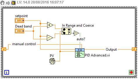
When I use a PID. VI to set pressure, when the PV nearby OAS, I want the PID.vi hold its output, but I have no idea to set the parameters of dead zone! (can not find the definition of dead zone)
An engineer PLC said that the dead zone is a common parameters PID, but idon't know not how to configure in labview pid!
Help, please, thank you!
You've already written that you have to do. A possible implementation is simply "freeze" the output of the PID controller. Use the "advanced version" of the screw of PID (normal or with automatic adjustment in case of need).
-
PID regulator - ECP rectilinear model 210
Hello world! I'm working on a PID controller for a system of one-basket (ECP model 210) in LabView. However, I don't think I properly use the vi of PID. Trying to get the position of the plow changed by the set value in the PID, but the system fluctuates only. If anyone can offer advice, I would be very happy.
Thank you!

Hi so1id,
Check your winnings, it is possible that you have your P gain set too high
Kind regards
-
The 12v DC motor PID regulator
Hello world
I want to order a motor to power DC 12v by using the PID control 8.2 toolkit.
-a closed-loop control system
-using a DAQ model: NI USB-6008
-How to control of motor speed DC 12v with PID control
Im stuck to get pid.vi and I wanted to know what the problem is.
pls help me on my problem, if can pls an example VI for me
Thank you!
Well, there are a lot of things you need to do this, the software LabVIEW being only a part. First, most of the DAQ cards will be not enough power source to actually power a motor, especially a USB6008, so you will need a form any driver/power of the amplifier. For closed loops, you will need feedback to tell you what the rotation of the engine is usually a wheel split with a LED and a sensor (if it is a school project or hobby a source you could look at is an old mouse wheel). With these two you so a way to drive the motor and then detect its motion. Then you can get the idea to PID, which takes the feedback (regardless of the sensor to find you using the) scaling so that it matches that you use and apply to one of the PID equations to match the target value.
-
I designed a pressure regulater (itself is a while loop) to run in a loop for example, I used a PID controller. Right now this regulater works well for the first iteration of the loop for. But from the second loop for, it didn't work anymore. I noticed there are a number of cycles in the PID controller, I don't know is there relationship with her or not. Is it possible to adjust it and let it work continuely in a loop.
Thanks in advance.
I think that you can solve your problem by simply connecting the time loop iteration counter (terminal blue 'i') through a = 0 (equal to zero) node at the entrance to reset PID function. What I think that you see who is on the second iteration of your for loop exit PID is from where it stopped when you have completed the first for loop iteration, and you can fix this by resetting the service PID once per loop iteration for.
-
Regulator PID very slow to reach the value Point and zeros process Variable when it should not
Hello
I am using a PID controller to regulate the emission of a filament current in an ion gauge, but I'm running into several problems.
The first and less important, are the controller of PID VI takes at least 5 minutes to get the current where it needs to be. Is it possible to speed this up?
The second and more important, are that the PID controller tends to zero the process variable before you start the process of getting the close process of the target value variable. This can be seen in the attached VI: I write 5.8 volts voltage filament - something I did at the beginning to try to get the controller PID for the process close to the target faster - value variable but when the PID controller starts to do his thing, he kills the tension before anything, rather than rise of 5.8 V.
The attached VI is a single which has these problems. VI actual ion gauge controller I've written has the same problems, but in a form even more frustrating. I have a while loop set up for the filament voltage to where it should be (using a PID controller) first and foremost, then a loop of data acquisition, which also includes a feedback loop in the form of a PID regulator to maintain the filament voltage. When the second PID controller starts to run, it concentrates the tension that the earlier had set, taking another 5 + minutes to reach the point where we can take data and giving us 5 minutes of false data in the process!
Does anyone know why PID controllers are behaving like this, and what can I do to fix/work with this behavior?
Hello
It seems that PID VI will always be 0 for the first iteration. You can, however, use the advanced PID VI and set up the first iteration in manual mode. After subsequent iterations, you could then define this automatic mode and there will be a transition smoothly. I think this will give you the desired behavior.
-Zach
-
Hello world
I have worked on a project with labview since a few months now and I have reached a point where I need help.
Basically, this next part of my project requires me to drive a linear actuator to apply a force to the end of a tree, with a load cell between the actuator and the tree, giving me the real force applied.
I need to use a PID controller to maintain a constant specified weight on the end of the shaft, which in itself should be simple, but I have a problem with the way in which the actuator is driven.
The actuator is powered by a H-bridge which has 3 separate entrances to drive the cylinder:
direction = high/low 5v logic 0v low high
break = high/low 5v logic 0v low high
Speed = pulse width modulation
My plan was to use a PID regulator to adjust the PWM in H-bridge by adjusting its cyclical relationship between 0.10 0.90 (slow) (fast), then using basic functions of comparison between the set value and the process variable to control the direction and break logic. So, for example...
I want it to apply 5kg on the end of the shaft
my set point is 5 and the variable is 0, so labview applied logic senior management (to go ahead) and low logic at the break (to pass) and the PWM is adjusted to focus about to set.
I cannot get this to work however and I was wondering if there was a better way to do it?
I understand that it might seem unclear, so I hope that I explained well enough!
Thank you very much
HCook
hcook wrote:
The task of WOB speed, that is out of the PWM of the bridge: keeps telling me that the specified resource is reserved and will not work after my first race. This has something to do with the PID does not?
May affect the PID does not. Which DAQmx functions return the error? My guess is that it's the DAQmx Timing, which is probably not necessary. The task must already be configured for continuous samples in the project or measurement and Automation Explorer.
hcook wrote:
Also, when I run the program in manual mode, where I move the actuator manually by and adjust the weight based on the load cell signal, I get an error when I adjust the operating factor. He informs me that the PWM must complete a full cycle before the duty cycle can be adjusted. Now, the rate at which im changing the duty cycle manually are no where near the same speed a PID can adjust and it is why I am having the same problem in automatic mode.
What is your frequency PWM? Your loop rate must be lower than that to ensure that you do not get this error. At the present time that you use the loop at 100 Hz, so if the PWM is less than that, and you use a cursor (which can generate a large number of new values quickly when you move it) to control the market factor, you may see this error.
What is the purpose of DAQmx task accomplished in this loop?
-
Hi guys,.
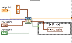
Im a software using advanced LabVIEW PID and hourly programming. But as my gain change, the output does not accordingly with my gain. For example:
Error = 10
Gain = 10
Output = 100
Then
Gain = 0, 01
Output = 100 supposed to be output = 1
Looks like transfer smoothly? I couldn't tell.
Yo have any idea why? The VI of "PID Gain schedule example" change accordingly with the error output. But mine is not. I hope you guys could help

Not the Gain annex vi does not change your output according to the entry it will select all of the gains that you want to use. In a certain type of profiles, we will have to use a different set of earnings, so in these cases, you can have a different set of gains and which apply accordingly. For your business simple PID must be suffucient.
-
PID control with big delay in the process variable
Hello
My goal is to control the temperature via a valve and heat exchanger. I proceeded variable (temperature) measured from a hose. This temperature should be raised a few degrees with a heat exchanger. So basically I need to order a valve that allows the water to flow through the heat exchanger to raise the temperature to the desired level.
My original plan was to use a base PID regulation to operate the dispenser. However, it is about 0.5 to 1 minute of delay time in the temperature probe after I opened the valve, which increases the temperature. This leads to a situation where the PID regulation valve fully open during this period (trying to get the temperature rise). Then once the temperature begins to rise it fires quite quickly. PID begins turning the tap off almost immediately, but because of the time delay in the sensor, the temperature exceeds seriously. This led to severe oscillation and at worst unstable processes. I tried to adjust the PID control to "predict" the timer to close the valve in advance to minimize the excess, but failed.
I would appreciate if anyone has any ideas how to make this type of control with Labview PID functions. I also wonder if there is a better type of control procedure for this scenario as a PID control?
-Lars
This is a very common situation in the heating control, and generally PID can be adjusted to make it work. How do you do the tuning? If you do it by trial and errors, you have little chance to succeed. For a slow process with time delay, I like to use the method Cohen Coons, or similar open Ziegler-Nichols-loop method. The idea is that you temporarily remove or disable the PID. Set the valve in a fixed position and wait for the temperature to stabilize. Then, change the setting of the valve and record temperature at regular intervals data until the temperature is stable again to a new value. Use these data to get the initial values of PID using the equations provided by the tuning method you choose.
-
Manual of PID for transfer Auto smooth
Hello
I am using the PID command for a pump to ISCO syringe with manual Steplessly in automatic control, but I can't seem to make it work.
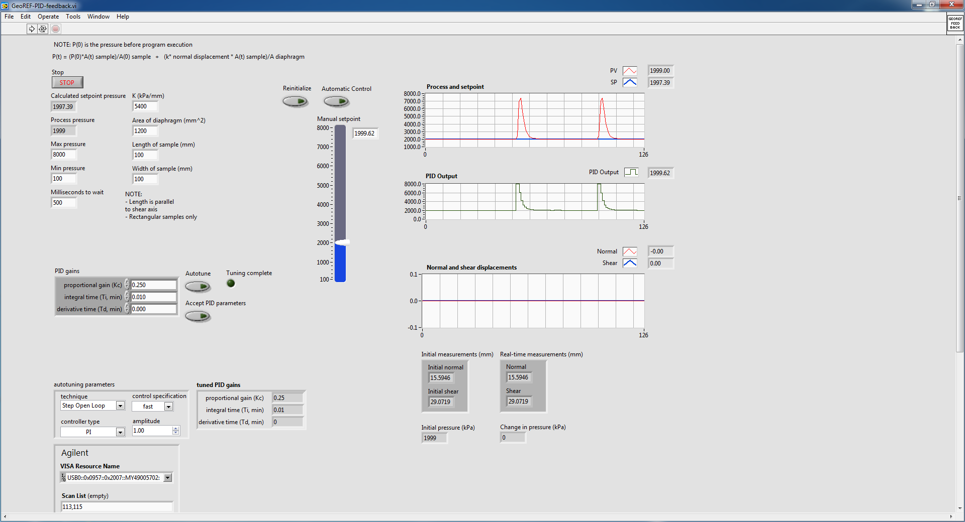
This shoot-syringe has an entry and exit pressure and is used to apply a force to keep the vertical movement of a constant of the sample. The amount of applied pressure is related to vertical displacement by an equation that appears in the attached VI. This VI aims to apply a variable force according to the displacement of the sample in order to try to keep moving 0.
Here is some general information on the pump that I use:
The pump is autonomous and can independently maintain pressure regardless of the LabVIEW PID controller. The pump only takes pressure of LabVIEW controls and maintain this pressure until another pressure control (I think that the pump integrated into the controller itself is a regulator PID.)
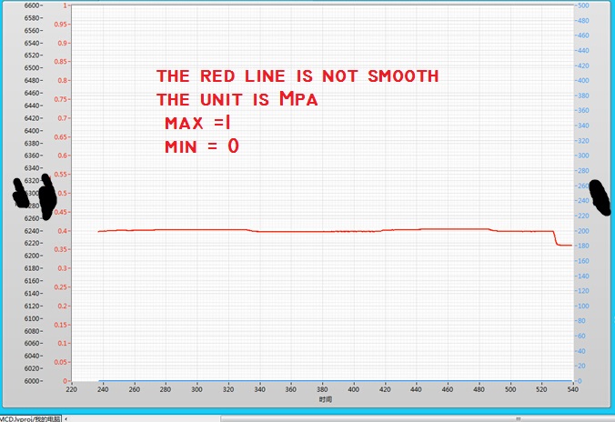
The problem I have is if I start the VI with the pump at a constant pressure (using the hand control with advanced PID VI) and crossing the wire to automatic control, the advanced PID VI immediately shows the pump to adjust the pressure up and then slowly bring it down to the steady state. This happens even if the hand control pressure is stable and identical to the auto set pressure. This following image details what I'm talking about:
The pump is in steady state, as shown in the diagram of pressure and the value in manual initially and then toggled mode on automatic control (designating the huge bump). I did it twice to show what happens when I go back. Manual automatic is without suddenly, because I used a local variable to constantly change the manual set temperature.
I did some troubleshooting and experiment and here are some of the results that I found:
1. when going from manual to automatic control, PID regulator sets the maximum pressure and then slowly bring it down to the set value
2 when it is cold from the VI in automatic mode with true to reset, the PID controller sets the pressure at a minimum and then slowly bring it up to the set value. This occurs even if the value of the original process is close to the set point (feed the actual value in the PID controller before execution also does not help.)
I also tried to play with the gains of PID in VI and found that if I turn off the 'I' and parameters "D" (together the two to 0), I no longer suffer from the huge bump, but the PID controller can bring the real set point value as there is always a lag.
I don't know if this is a result of bad PID tuning, but after the initial bump in the transition between manual and automatic, the PID controller seems to be able to maintain the correct pressure well.
The reason why I am using a PID controller rather send the pump controls (since it can independently maintain pressure) is because it is much smoother.
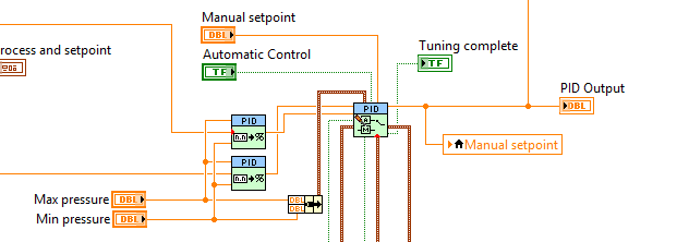
In the attached VI, there are a few side screws that are called that are specific to the pump and the LVDT used for detection of vertical movement. I do not think that they have an effect on why I don't get a transfer smoothly without jerking, so I only put comments to explain what they are doing.
I found another thread in forum with a similar question, but none of the solutions posted it seemed to have helped me. Here is the link to this thread:
http://forums.NI.com/T5/LabVIEW/PID-manual-to-auto-bumpless-transfer/m-p/3180609#M920098
Thank you.
Best regards
Victor
Your topology is not quite how we recommend that you make the transfer smooth. Can you do something like this?
Who will do manual setpoint pressure (units) and you need to update your gain, but it should follow. What is an option?
-
Hello
I'm trying to implement the PID loop, but face some problems.
Entry:-the engine in terms of PWM feedback fixed duty cycle and variable frequency.
Output:-is set to frequency and vary the duty cycle.
Observation is regardless of setpoint motor is running in the range defined by PID output range.
Please help solve this thing.
Attachment:-exit running Vi & Vi also rasthaus.
Hi Nitin,
so limit you the output of PID to a very small range range - and then you wonder, why the PID regulation is not outside this small beach of work?
Output:-is set to frequency and vary the duty cycle.
BTW. Why do you establish exit [1700, 1900] when you want to a duty cycle as output value? What kind of cyclical report uses values such as '1800 '?
-
I have a problem with the simulation in Matlab 6.5 and LabVIEW for PID controllers
I have a problem with the simulation in Matlab 6.5 and LabVIEW. I have a few methods for granting regulators PID in MATLAB to go but not of LabVIEW. Degree of international teams of two transfer but when I passed to the fourth degree is no longer working. We have changed the formula to calculate the parameters for the fourth year and gave me some good values for assignment of Matlab, but when I put on LabVIEW are not resolved. the formulas are available in PDF format and are. Please help me and me someone if possible. Thank you
Lim.4 generation in comparison methods and the MATLAB program settings are for the service of transfer to the second degree.Hello Lascarica,
I noticed that you are using the screw of PID. Gains on these screws are based on TIME instead of GAIN. You should be able to build a PID regulator and vary the gains and then compare the results.
-
Hello
Can anyone help. I am currently doing a project for College. Basically, my plan is to use labview to control a temp of DP watlow controller to turn on a heater off the coast. I want only basic as set functions of preforms and read the temperature and possibly graph temperature. I will also put in place a regular thermostat and relay to switch on and switch off the device and use it again the PDD to monitor and graph of this temperature. My project is basically to graphically display the benefits of PID regulation.
Now, here's my problem. I'm pretty much a perfect beginner when it comes of labview and programming. I downloaded Labview instrument for the DP controller drivers, but I have no idea how to use. I got the connection from my laptop to the watlow via internet but I have no idea on how to get on the cat of my watlow labview. When I opened the drivers of instruments is just a load of Subvi and I don't know what to wire to the place where, or what to use to get a simple button on the front panel by increasing or decreasing the set temperature.
Any help would be appreciated to massivly
Thank you
Hi, Declan,
Yes, they are the right drivers. I assume you are using LabView 8.0 or later version. Just to help you get started, here is the link which explains the fundamental band of instrument drivers.
Internally, the VI in an instrument is organized into six categories.
(1) ' initialize VI"establishes the communication with the instrument and is the first driver of the instrument calls VI
(2) "set screws" are software routines that configure the instrument to perform specific operations. After calling these VI instrument is ready to take the step.
(3) ' command screw action/Status' the instrument to perform an action or to get the current status of the instrument or pending operations
4 "data" screws from the instrument of transfer or date
(5) "utility" VI run various auxiliary operations, such as reset and self-test
(6) ' close' close VI ends the connection of the instrument software. It's the last pilot instrument called VI.
There is a help function (?) the top tablet of your block diagram window, if you click on that and put your cursor on the VI it tells you the function and what it takes to be connected in VI. This should be enough to get you started.
There are also a few examples to the finder OR example-> entry material / output-> instrumentation drivers-> labview plug-and-play (if you can't find them please install the instruments from hereaggilent) who should give you an idea of how works driver programming and instruments. This should be enough to get you started. I'll try to find you some examples that are related to your project.
Also if you are in the United Kingdom and needs help with learning LabView programming you can call 01635 523545, and they can organize courses for you.
Best regards
Maybe you are looking for
-
Am I missing some Apple loops loops? I can't find a strike simple triangle or a scan of a tambourain (chime). I need one of these for a project. Any suggestions? Thank you!
-
Cannot send mail in verizon iPhone 6
I have an iPhone on day 6 and cannot figure out how to get my verizon account to send mail. I can receive mail without problems, but when I try and reply or send a new email I get an error message "the user name or password is incorrect" but not beca
-
How can you correct error code 800 F082F I get when trying to install SP1?
How can you correct error code 800 F082F I get when trying to install SP1?
-
A current version of running when you try to install Silverlight.
Original title: Silverlight hate vista: vista hate silverlight? I tried for a week to get silverlight to run on vista. I went to download view all silverlight that I remind you I did that during the fight a week and I have 8 downloads the client silv
-
BlackBerry BlackBerry Blackberry in India LEAP Leap care Protection Plan?
Hello I try to use Blackberry Bond Support because I try more click on 'BlackBerry Care Protection Plan' view but always found that "not found the requested URL was not found on this server." I'm looking for that, in India, this plan applies to the B