The 12v DC motor PID regulator
Hello world
I want to order a motor to power DC 12v by using the PID control 8.2 toolkit.
-a closed-loop control system
-using a DAQ model: NI USB-6008
-How to control of motor speed DC 12v with PID control
Im stuck to get pid.vi and I wanted to know what the problem is.
pls help me on my problem, if can pls an example VI for me
Thank you!
Well, there are a lot of things you need to do this, the software LabVIEW being only a part. First, most of the DAQ cards will be not enough power source to actually power a motor, especially a USB6008, so you will need a form any driver/power of the amplifier. For closed loops, you will need feedback to tell you what the rotation of the engine is usually a wheel split with a LED and a sensor (if it is a school project or hobby a source you could look at is an old mouse wheel). With these two you so a way to drive the motor and then detect its motion. Then you can get the idea to PID, which takes the feedback (regardless of the sensor to find you using the) scaling so that it matches that you use and apply to one of the PID equations to match the target value.
Tags: NI Software
Similar Questions
-
Modbus, writing in the registers by PID regulator
Hello
Can you please help... I'm new here
I try to use a registry read, send the value to a PID vi, then write in a register.
I've attached an example of using a temperature regulator.
I get errors whenever I try to connect using clusters, clusters, etc..
My material and comms are all good, I have values and all gauges reading ok, but it seems I can't work on how to manipulate the data through a vi of PID.
Your help is very appreciated.
Thank you
1 rearrange your functions so that your reading of data occurs before your writing of data. You can do 1 2 3 4. Right now your code run step 3 before step 1 and impossible to know where should go steps 2 and 4.
2. your writing log has an entry called registry where your worth is going. There is an entrance to U16. Your PID provides a DBL. You need to read the manual of the device know how to code the PID output floating point number into an integer. It may be a simple by multiplying by a factor of scale and he rounded to an integer.
3. your Modbus Read is for several records. You will get a table 1 d of readings, but it will not be 1 element. You can use the table to Index, and then together with setpoiint wire to feed in the gauge of multi-aiguille. Since you data will be an integer U16, you may need to perform a scaling to convert an integer in all that but it represents the temperature.

4. don't forget that you must connect your process in the PID function value.
-
Hello
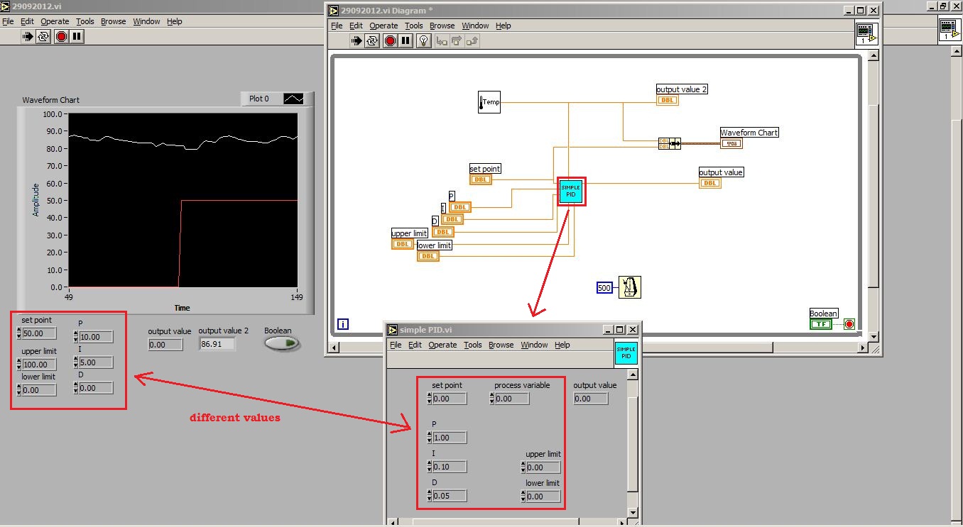
I use an old version of LV, LV 6i to be exact. Now I'm building a control temperature for simple PID control of a room. I use as my NI PCI-6024E data acquisition card. But, in the middle of trying to get the right program, I stuck to the PID regulation. I use the .vi "simplePID" and connect everything that is necessary, the limits of high and low, the parameters (P, I and D), set point, take Subvi 'Temp'.vi, and connect to the variable process and exit the .vi 'simplePID' to a chart.
The problems occurred when I run the application, the temperature did give lectures as usual and I set the setpoint and limits and also settings. But it seems that the "simplePID".vi don't not responds to these values. As the program is running, I clicked on the "simplePID".vi and see that the value of the settings inside there is not changed to the values that I have previously set. Why is happening. I'm missing something important.
I have attached photos and my VI for your reference. Thanks in advance.
What do you mean by Reentrant is on the right execution tab?
I checked it and its already "ticked" and I checked the Reentrant and try to run the VI, still no response from the simplePID.vi.
-
I designed a pressure regulater (itself is a while loop) to run in a loop for example, I used a PID controller. Right now this regulater works well for the first iteration of the loop for. But from the second loop for, it didn't work anymore. I noticed there are a number of cycles in the PID controller, I don't know is there relationship with her or not. Is it possible to adjust it and let it work continuely in a loop.
Thanks in advance.
I think that you can solve your problem by simply connecting the time loop iteration counter (terminal blue 'i') through a = 0 (equal to zero) node at the entrance to reset PID function. What I think that you see who is on the second iteration of your for loop exit PID is from where it stopped when you have completed the first for loop iteration, and you can fix this by resetting the service PID once per loop iteration for.
-
PID regulator takes advantage of the transfer function of the model sys
Hello
I need to find a controller for my system...
I have my system as transfer function model and I want to find the pid of the gains of this system by using its transfer function!
All block in labview 8.5 to do this step?
Concerning
Hello
Maybe this link will come close to the feature you're looking for:
Analytical design of PID VI
http://zone.NI.com/reference/en-XX/help/371894E-01/lvctrldsgn/cd_pid_design_pal/
This function was introduced in LabVIEW 8.5 in the Control Design and Simulation Module. There is a limitation, because this process analysis based on one or more transfer SISO (single Input Single Output) functions. The help article above comes from aid in 2010. Below, I've included the 8.5 reference:
-
Where can I find the credit of the Attorney general and the Apple E-book class regulations?
I was advised that I have a credit on my account, but I can't find this information in my account from anywhere. Help!
You did iBook purchases during the period covered by the regulations?
Did you sign in the iBooks store to see if there is a credit on your account?
See your credit balance - Apple Support iTunes
By the end of 2012 Mac minis, macOS? Watch, 38 mm silver AL, Watch BONES 2.2.2; iPad 2 Air & iPhone 6 + iOS? Apple Airport Express
-
750 - 150xt envy: envy 750-150xt provide only pci - e 6pin connections and that's all the 12v.
New
Envy of 750-150xt/500w power supply only PCI-e 6-pin drop points. No molex. I would like to add my card usb 3.0 at envy that requires 4-pin molex and 5 volts. All PCI-3 pins are 12v or ground. No source of 5 volts. Any suggestions? I spent 6-8 hours phone with HP and no one seems to understand the question. Please give me some advice.Hello
Tap into a SATA power connector open using a molex to SATA Adapteror use a SATA to molex splitter. NewEgg.com offers plenty of choices that should meet your needs.
Thanks for posting on the forum.
-
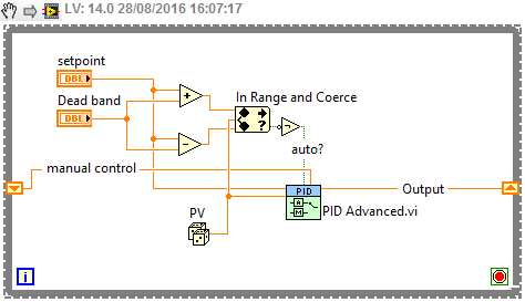
How can I set a deadband for PID regulation
When I use a PID. VI to set pressure, when the PV nearby OAS, I want the PID.vi hold its output, but I have no idea to set the parameters of dead zone! (can not find the definition of dead zone)
An engineer PLC said that the dead zone is a common parameters PID, but idon't know not how to configure in labview pid!
Help, please, thank you!
You've already written that you have to do. A possible implementation is simply "freeze" the output of the PID controller. Use the "advanced version" of the screw of PID (normal or with automatic adjustment in case of need).
-
PID regulator - ECP rectilinear model 210
Hello world! I'm working on a PID controller for a system of one-basket (ECP model 210) in LabView. However, I don't think I properly use the vi of PID. Trying to get the position of the plow changed by the set value in the PID, but the system fluctuates only. If anyone can offer advice, I would be very happy.
Thank you!

Hi so1id,
Check your winnings, it is possible that you have your P gain set too high
Kind regards
-
Structure of the event - controlled motor not variable
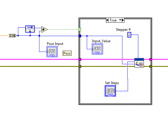
I have a state machine that includes certain structures of the event. These event structures are used to control stepper motors using an Arduino Mega microcontroller. I'm using labview in 2012.
The entrance to one of the events is the variable "pour the entry. I want to use it to control the motor speed and direction.
If I control the motor as shown in the attached image Working.jpg, then the motor functions correctly. If I fix the motor to the steps variable # then the engine moves at the speed set in the right direction depending on whether the entry "pour" is positive or negative.
However, I want to control the speed of the engine, not the number of steps, with the variable "pay Input". I checked that the values read by the indicator image INPUT_VALUE works do not are of the same order as the specified values, working, by using the "Set Speed". When I connect the value of the entry to the spindle speed of the motors of the Arduino (not_working.jpg) icon, the engine is running, apparently indefinitely at maximum speed. I don't understand why there is a difference in motor behavior between the value provided by these two methods at the entrance to the speed of the motor. I am confused by the present and don't know where to go from here.
The structure of the event somehow behaves differently when taking a value from outside the structure to this data inside? or y at - it something to do with the opening of the structure on its first loop?
I have also attached my vi together, even though she may not be the easiest to follow and requires an arduino Mega to run.
Carlr wrote:
I have a state machine that includes certain structures of the event. These event structures are used to control stepper motors using an Arduino Mega microcontroller. I'm using labview in 2012.
The entrance to one of the events is the variable "pour the entry. I want to use it to control the motor speed and direction.
If I control the motor as shown in the attached image Working.jpg, then the motor functions correctly. If I fix the motor to the steps variable # then the engine moves at the speed set in the right direction depending on whether the entry "pour" is positive or negative.
However, I want to control the speed of the engine, not the number of steps, with the variable "pay Input". I checked that the values read by the indicator image INPUT_VALUE works do not are of the same order as the specified values, working, by using the "Set Speed". When I connect the value of the entry to the spindle speed of the motors of the Arduino (not_working.jpg) icon, the engine is running, apparently indefinitely at maximum speed. I don't understand why there is a difference in motor behavior between the value provided by these two methods at the entrance to the speed of the motor. I am confused by the present and don't know where to go from here.
The structure of the event somehow behaves differently when taking a value from outside the structure to this data inside? or y at - it something to do with the opening of the structure on its first loop?
I have also attached my vi together, even though she may not be the easiest to follow and requires an arduino Mega to run.
You have a very inappropriate design of "state machine" - even if you do not have same event in more than one of your structures of the event (in addition to time-out), looks that get some of your treatment to go forward until you get something very specific (and in which none of your other user events are being processed).
I strongly suggest that first set you design of State machine - perhaps follow producer/consumer Design Pattern (events) rather than having everything in a loop, the way you have. If you keep everything in a loop, you should consider redesign so that you at least allow events to deal with rather than stay in a loop for an indefinite period!
In any case, in the case where work, you send variable "Set Speed (steps per second)" for engines step by step write vi. But otherwise, you're feeding 'Entry for' value - are they the same? And to let you know, you send only command "write" step by step when the input value to be paid.
It's a big mess! For starters, look at the attached picture, get rid of your structure of the event that has "for the entry" and replace it with what I showed in the picture. (In fact, all your event structures can / must be replaced with a similar logic.) Does not need the event structure in all this, you're just more complicated it must be!
-DP
-
Problems when you try to move the 3 stepper motors
Hello
I have problems when I Isaiah to compile a 3 stepper motors control program.
I have 3 steepest motors and controller (3 SMCP33 + SMCP33-EVA) nanotec.com, they also provide an example of Vi to control a motor that works successfully, but problems happen when I try to adapt the program to try to start the 3 Motors. The final application for this is going to be a Cartesian robot XYZ so finally I need to program coordinates to move the 3 Motors.
I am new to LabVIEW, so what I do is try to adapt the nanotec example to order 3 engine as follows.
-J' I assign each engine a different address, doing so that I can run each engine separately. But when I try to run 3 programs at the same time, they work but all moving them the engine (the first that has been run).
-If I try to make a sort of sub - VI is the same thing, only one motor is driven.
-Moreover, I get a warning when I try this, I have attached a screenshot of this.
I have attached the Vi and texture it to improve my description.
I woul be grateful if someona can help aport.
Kind regards.
Thanks for posting the original. By comparing the two screws immediately gives an indication of what might happen.
In the picture you posted you circled two places where you changed the address of the reader. In the Example.vi - Nanotec address of the player is connected to about 14 seats. So when you try to run the other engines in your modified program, the 12 places, you have not changed the address of the player are always preset to motor 1.
What you need to do is to divide the example VI in at least three parts. The first part initialization. The next part moves the engine. The last part ensures that the engine is stopped and made any required another stop. Each party becomse a separate Subvi. Each Subvi has the address of the reader as input. The initialization and shutdown parts are placed before and after a while loop. The movement parts are inside the loop. You can use three of each sub - VI for the three engines or a Subvi combined with subVIs move three to manage all three engines.
I can't say what approach might be better without knowing more about how you plan to order the engines - one at a time or all three at the same time, what kind of feedback is used, how management mistakes and other topics.
Lynn
-
Regulator PID very slow to reach the value Point and zeros process Variable when it should not
Hello
I am using a PID controller to regulate the emission of a filament current in an ion gauge, but I'm running into several problems.
The first and less important, are the controller of PID VI takes at least 5 minutes to get the current where it needs to be. Is it possible to speed this up?
The second and more important, are that the PID controller tends to zero the process variable before you start the process of getting the close process of the target value variable. This can be seen in the attached VI: I write 5.8 volts voltage filament - something I did at the beginning to try to get the controller PID for the process close to the target faster - value variable but when the PID controller starts to do his thing, he kills the tension before anything, rather than rise of 5.8 V.
The attached VI is a single which has these problems. VI actual ion gauge controller I've written has the same problems, but in a form even more frustrating. I have a while loop set up for the filament voltage to where it should be (using a PID controller) first and foremost, then a loop of data acquisition, which also includes a feedback loop in the form of a PID regulator to maintain the filament voltage. When the second PID controller starts to run, it concentrates the tension that the earlier had set, taking another 5 + minutes to reach the point where we can take data and giving us 5 minutes of false data in the process!
Does anyone know why PID controllers are behaving like this, and what can I do to fix/work with this behavior?
Hello
It seems that PID VI will always be 0 for the first iteration. You can, however, use the advanced PID VI and set up the first iteration in manual mode. After subsequent iterations, you could then define this automatic mode and there will be a transition smoothly. I think this will give you the desired behavior.
-Zach
-
need suggestions on the way to a position on a motor control with current continuous
Hi, I'm a newbie with labview
I'm doing a position on current motor control continuous. I use a USB 6259 to generate an output voltage and acquire the angular position of a coder.
I enclose my system of proaction
How can I transform into a feedback system, with a given reference signal?
Thank you
The "cascade dc motor speed regulator" example uses the Control Design and Simulation Module, and it is thought to control a motor which is simulated. Since you have to acquire data from a real system the standard while loop is correct.
With respect to the operation of PID control, you can take a look at the following examples:
-
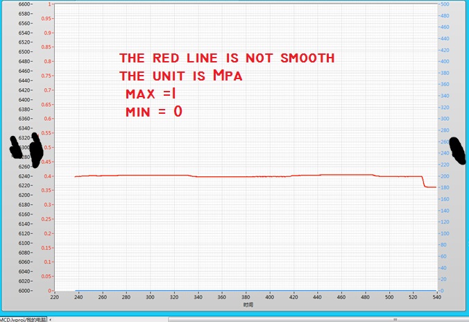
PID control with big delay in the process variable
Hello
My goal is to control the temperature via a valve and heat exchanger. I proceeded variable (temperature) measured from a hose. This temperature should be raised a few degrees with a heat exchanger. So basically I need to order a valve that allows the water to flow through the heat exchanger to raise the temperature to the desired level.
My original plan was to use a base PID regulation to operate the dispenser. However, it is about 0.5 to 1 minute of delay time in the temperature probe after I opened the valve, which increases the temperature. This leads to a situation where the PID regulation valve fully open during this period (trying to get the temperature rise). Then once the temperature begins to rise it fires quite quickly. PID begins turning the tap off almost immediately, but because of the time delay in the sensor, the temperature exceeds seriously. This led to severe oscillation and at worst unstable processes. I tried to adjust the PID control to "predict" the timer to close the valve in advance to minimize the excess, but failed.
I would appreciate if anyone has any ideas how to make this type of control with Labview PID functions. I also wonder if there is a better type of control procedure for this scenario as a PID control?
-Lars
This is a very common situation in the heating control, and generally PID can be adjusted to make it work. How do you do the tuning? If you do it by trial and errors, you have little chance to succeed. For a slow process with time delay, I like to use the method Cohen Coons, or similar open Ziegler-Nichols-loop method. The idea is that you temporarily remove or disable the PID. Set the valve in a fixed position and wait for the temperature to stabilize. Then, change the setting of the valve and record temperature at regular intervals data until the temperature is stable again to a new value. Use these data to get the initial values of PID using the equations provided by the tuning method you choose.
-
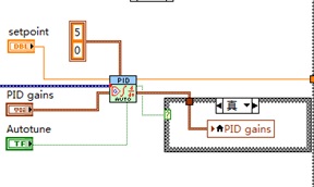
I have a problem with the simulation in Matlab 6.5 and LabVIEW for PID controllers
I have a problem with the simulation in Matlab 6.5 and LabVIEW. I have a few methods for granting regulators PID in MATLAB to go but not of LabVIEW. Degree of international teams of two transfer but when I passed to the fourth degree is no longer working. We have changed the formula to calculate the parameters for the fourth year and gave me some good values for assignment of Matlab, but when I put on LabVIEW are not resolved. the formulas are available in PDF format and are. Please help me and me someone if possible. Thank you
Lim.4 generation in comparison methods and the MATLAB program settings are for the service of transfer to the second degree.Hello Lascarica,
I noticed that you are using the screw of PID. Gains on these screws are based on TIME instead of GAIN. You should be able to build a PID regulator and vary the gains and then compare the results.
Maybe you are looking for
-
How can I change where firefox stores the logs?
I run 'Fox on a flash drive, because it allows me to keep my history, bookmarks, etc. all together while using ' Fox on several different computers. I learned recently that Firefox was leaving newspapers on the hard drives of each computer, that I ra
-
Mac crashes when you click docking station
Yosemite 10.10.5 running. Intermittently, when I click on an icon in the dock, my iMac is suspended for anywhere from 10 seconds to a minute or more. Repairing permissions, zapping the PRAM and reset SMC do not help. Any ideas?
-
I want to create communication between two laptops by Bluetooth series
Hello I'm trying to accomplish communication series between two laptops via a Bluetooth connection. The two laptops are NOT portable Toshiba, but they work together the Toshiba Bluetooth Stack For Windows. They have both also use the default Bluetoot
-
Hello Is there an STD for the coding on test bench? So we have some coding guidelines to follow? Thanks in advance Biki
-
I have vista and I spent the last three hours, trying to solve this problem. I concluded that I needed to uninstall Java and of course it uninstall not because of error 1719. I found an incredibly detailed by a microsoft tech message, but none of t