size_t numerical control by GUI
I'm getting some CVI behaviors for 32-bit application and 64-bit. Specific, I want to build the application so that I only need re-compilation for each output of 32-bit or 64-bit. One of them uses integers signed and not signed in entrance and exits in the GUI. I would like to first of all operating system data type directly in the GUI, but ssize_t and size_t types are not available in the interactive tools. So I create a GUI for 32 - bit
-using as digital input (hot)
-using digital as outputs unsignedInt (indicator)
After the loading of the GUI depending on the hand, I change the attributes of data type control:
-the program "recall" function Committee dependent integers from the OS as option
-SetCtrlAttribute (mainp, PANEL_INPUTVALUE, ATTR_DATA_TYPE, VAL_SSIZE_T);
-SetCtrlAttribute (mainp, PANEL_OUTPUTVALUE_1, ATTR_DATA_TYPE, VAL_SIZE_T);
-SetCtrlAttribute (mainp, PANEL_OUTPUTVALUE_2, ATTR_DATA_TYPE, VAL_SIZE_T);
I get no error in compilation. As expected, nothing really changes for 32-bit debugging i.e. or errors. And when running 64-bit debugging it starts also without mistakes (obvious). And it goes beyond the limit of 32-bit of 2 ^ 31.
Now, I try an alternative: I set the GUI for 64 - bit with example data types int64 and unsigned int64. When data types are changed after the loading of the IUR depending on the hand, I get no fatal errors:
-For the first line for the digital input: the attribute passed is not valid (error - 46).
-For the second and third lines for outputs digital: invalid control ID (error - 13).
- And subsequently, all three figures disappeared from the GUI.
These error happens when I run it in 32-bit as 64-bit.
The disappearance of the controls look like somewhat like explained before. However, the GUI is new and build CVI2010.
(http://forums.ni.com/t5/LabWindows-CVI/edit-numeric-control-of-type-int64/m-p/1411662#M50699)
Q1: Is there a limit on the construction of the GUI with int64?
Q2: Is there a solution where I can use VAL_SIZE_T and VAL_SSIZE_T when the GUI is generated manually?
I use:
Windows 7 x 64
CVI2010 (10.0.1)
Kind regards, Jos
Hi Jos,
The runtime error is caused by the fact that these controls do not exist in the expert group. You can see more clearly, what happens if, after you save the file, you close the window, and then reload the file. You will notice that the two controls will be missing.
Controls are not saved when using the 64-bit data types is the IUR is configured to use the CVI 8.1 format. You can see in the lower right window of the user interface editor. Because 64-bit in the user interface controls data types were not been introduced prior to version 8.5, these controls cannot be included in a 8.1 UIR.
We have already identified this scenario as a major flaw in usability: when you save the IUR in an older format, the CVI should show you a warning telling you all the controls or other features, that were not saved after save in the old format. This has been fixed in a future version of the CVI, but, until then, it's something you have to look out for.
To save the file to the CVI 2010 format, you must only select file > save as... and select 2010 than the version in the list "Save as type".
Luis
Tags: NI Software
Similar Questions
-
Hello
I am doing a program in Teststand combined with cvi and I have 3 problems:
1. I have a program on Teststand this is GUI runs in CVI, in this interface graphic I have 2 buttons and I want each button to run a different sequence in TestStand.
2. How do I make sure the MISTLETOE will remain open and visible, and TestStand will run sequences, I told her in the "background".
3. where can I find a guide for TS_ in CVI functions?
Thank you
Kobi
You can look at the following example to see how to develop a CVI GUI:
Dynamically control a GUI of LabWindows/CVI through several TestStand steps
What is a call from a GUI CVI sequence, you want to use the application manager, as shown in this document:
Loading program from a file of sequence in a TestStand operator Interface
You will find a guide for ts_ functions by opening the function for the simple function Panel and right-click in the box of ablank.
-
LabVIEW digital control does not raise an event changed value when the button entry is hit
I used to be able to type a value in a numeric control of LabVIEW, then press 'Enter' to trigger an event "changed value". Then at some point, this no longer works. I have to click elsewhere to trigger the event of value has changed. The up and down arrow keys work always, but just typing a number then press enter does not work. Is this a configuration settings got accidentally changed? Help, please!
-
change digital controls of type int64
Hello
in my UIR, I changed the data type of a numeric control to int to an int64. Unfortunately, I'm not able to increase the maximum... 2 ^ 63 should give a number in the order of 9 x 10 ^ 18.
However, if I enter the CNC 1E18 ' Maximum:' my value is changed back to 2147483697. This is much like a 31 bit value, not 63 bit...

What else I need to do to enable the 64-bit numbers is displayed?
Thank you!
(PS: CVI2010)
This will be corrected in 2010 SP1. The reason the scientific notation works for non-int64 data type is because CVI stores these numbers as doubles. For example, if the control data type is integer, and the user types "2e2", we use strtod who convert to 200.0. However, we do not use strtod int64, data types because the double data type has only 53 bits in the mantissa, so any number which is entered which is greater than 2 ^ 53 may lose precision.
In order to make the numbers entered in the work of scientific notation for types of data int64 in SP1, it will use strtod if there is an 'e' or 'E' in the string. This allows the user to use scientific notation, but the number may be different from what has been entered if the number is greater than 2 ^ 53. This behavior will be documented.
-
How to set the default value for the digital control on front panel?
How to set a default value for a numeric control of LabVIEW 2009 Front Panel? I have several input values that are actually configuration settings I want to settle with the default values of zero. I want them to be the values displayed when the façade first appears until the code is executed.
I really want to use the Minimum and Maximum limits by default for this because I still want to be able to define acceptable limits for values.
I would not be able to specify a default value of zero for these entries?
Enter the desired value, then "right click...... of default data of value to operations. Save the VI.
-
How to detect the event mouseclick-control
I am trying to relax the max property Z on the scale of a graph of intensity to be changed from the front panel. In the VI attached, I use an increment/decrement control and just detect a value change event (without taking into account the value of the control). It works very well, even if it's a bit of a hack.
I want to make them much more functional. My main question is this: How can I detect an event 'control-click '? I intend to use this event to change the max of graphic intensity by a factor rather than an additive value.
A second quick question: on the numerical control, is there a way I can get rid of the number in the display space and leave only the increment/decrement buttons?
Thank you
Allan
Are you talking about the button increase/decrease on a digital control? I thought you had Boolean separate to increment and decrement. It's hard. You can't be the PlatMods when using a value change event. You will maybe make your own controls inc/dec and update a digital indicator rather than use a digital command.
-
Dear friends
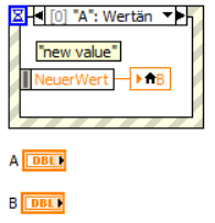
I have two digital controls in the front. Now I want to program numerical controls such as when I changed one of them another imposition of a change.
for example in the VI attached when I put 'A' 1 'B' must be automatically 1 to and when I changed 'B' 1 to 5 'A' should be replaced by 5 automatically.
Cordially Valentin
Hi VS,.
That's what it seems that for a value change event "A":
BTW. is it so hard to spell my name correctly?
-
I want to update the digital control by pressing a button
Hey,.
I'm in Labview 7.1
So I have a problem that seems like it should be very simple, but I have questions.
I want to increment a digital counter when the user presses a button to save their data, but labview allows only a digital output counter and not all take to the.
I want the variable a numeric control so that the user can increment/decrement it themselves if they feel the need to revive or ignore a number of test.
All solutions?
Thank you

-
In the code below, how is I've updated the generated random number GUI? I can't use a static method, because I may need more than one instance of the user interface and each instance must have its own unique output displayed. I can't combine the two class together because I want to serialize the controller, but NOT the GUI.
How the controller can change the GUI after the random number was generated?public class Controller{ public void makeNums(){ // creates random numbers at random times } } public class Gui{ private Controller control; public Gui(Controller control){ this.control = control; openGui(); // this method creates all the components of the GUI control.makeNums(); } }It is pretty trivial:
public class Controller{ private Gui gui; public void makeNums(){ // creates random numbers at random times } public void setGui(Gui gui) { this.gui = gui; } } public class Gui{ private Controller control; public Gui(Controller control){ this.control = control; openGui(); // this method creates all the components of the GUI control.makeNums(); control.setGui(this); } } -
Layer control sets in the objects of EDA
We use AutoVue in a process to review the design of Library objects because they are created. We have a lot (10,000 inhabitants) of these elements to be considered and would like to make the experience of the user as simple as possible. One of the heavier parts of the review process is to change the visibility of the layers. All these objects have a common set of layers (even the names and the order). We are trying to determine if there is a way to simplify the visibility of the layer. Here are a few thoughts we have and are looking for suggestions and alternatives.
Option 1
We know that multiple layer sets could be created where each defined controls the visibility of a set of layers. Sets of layers could then be stored in a file of markup. We know that the markup.map file control the relationship between the object being viewed and the file mark. We could change / programmatically update this file for each of the objects have in the same markup file. This seems to be the kind of a hack and has a number of holes that don't make it not very desirable.
Option 2
We know that the user interface can be changed according to the user. We believe that if we could create any menu items or need icons that set the visibility for the points of view of the users, it would make the process much more elegant and less tedious. Several questions come to mind in this option. The user interface can be modified to add additional menu or icons selection? An icon or a menu item to set the visibility of the layer? The method by which is running AutoVue allows to control the ultimate appearance and options that are available to the user? If we were to pursue this option, is there a recipe already in place that can guide us in the process?
All responses are greatly appreciated.Hi Charlie,
Please specify each of your EDA files have the same set of layers with the same names in the same order - it is crucial if you want to try to address the issue in a program or a batch way.
As we talked about earlier today in a separate thread, Option #1 (creating a single markup with saved views file and linking this markup to several core files) can cause problems. As you know, when AutoVue is not integrated with a DMS/PLM, the rate of increase is managed on the server AutoVue in the file markups.map... and then this file is ASCII and can be changed (not recommended), don't forget not that the mapping depends on exactly where it was opened the base file to and what protocol is used to open this file. So, if the same file can be opened in 2 different ways (for example once there of the computer of the user and once from a web URL), the markup will not automatically be bound at the same time. Option #1 can be too unpredictable.
This is why I would recommend Option #2. I will ask the experts to chime if they disagree, but I think that what you want to achieve is possible via the AutoVue API and can be broken down into 3 parts:
1. write the code base to turn specific layers
2 packing this code as a 'VueAction' custom so that it can be called as a menu item or custom toolbar
3. customization of the graphical user interface to expose this point of menu or toolbarPart 1 (code of activation/deactivation of specific layers) should be relatively easy. The AutoVue API includes a class called "com.cimmetry.core.PAN_LAYER", which represents a layer in a file (including ADM files). With the API, you can:
-The list of layers in the file running (VueBean.getLayersState)
Toggle layers as required (PAN_LAYER.setState (PAN_LAYER. STATE_ON) or PAN_LAYER.setState (PAN_LAYER. STATE_OFF))
Re-apply all of the layer update (VueBean.setLayersState)Part 2 (construction of a custom VueAction) is a little more complex, but it is explained very well in the new API Programmer's (http://download.oracle.com/docs/cd/E22156_02/otn/pdf/E22092_01.pdf) supplied with AutoVue 20.1.0 Guide. I recommend you to read the pages 20-22 and 30-35. You want to take the code from part 1 and package in the 'performer' of your custom VueAction method.
Part 3 (customization of the GUI) should also be relatively easy and are discussed on pages 62-68, the Setup Guide and Configuration (http://download.oracle.com/docs/cd/E22156_02/otn/pdf/E22093_01.pdf).
But rather than just saying 'read the docs', we now also provide an example prepared in advance of a customized with AutoVue 20.1.0 VueAction Client/Server deployment (I think that it is an optional component during installation). If you have included the installation, you will have the \examples\VueActionSample of your server installation folder. You should be able to use it as a reference to add your own custom in the applet VueAction.
There is another part that I had not included. In our separate thread earlier today, I think you mentioned you wanted only does not provide this customization of GUI for some users. If you want to control the GUI based on the user/group/role/etc, it's possible, but it will be to you to determine the user/group/role/etc and the applet JVue of script accordingly (i.e. dynamically the cmdlet to set the GUIFILE script parameter, or use the JVue.setGUI method).
Hope this helps at first.
Thank you
GrahamEDIT: If you prefer to automate the configuration of the layer as soon as the file is loaded - rather than having it as a custom menu or toolbar item - you can do that as well and it is much easier. In this case you always go through part 1 and write code to set the desired channels and implement you it as a 2nd applet as described in Oracle KM notes 754612.1 (https://support.oracle.com/CSP/main/article?cmd=show&type=NOT&doctype=HOWTO&id=754612.1).
Published by: user638792 on April 5, 2011 20:23
-
Hey everybody
at first, I'm sorry for my grammar, I usually do not use the language.
I have a problem with the pages. I want to create a clean list but I can't find the options. My list so far:
I have.
1.
one)
(("Here's the problem: I would like to have '" aa "), then '(bb)', 'cc') and so on.
Is it somehow possible to draw up a list that includes this numerical control? I've tried the ball from the text: 'aa')-> always aa) appears in the level, but I want to aa), bb), cc),...
At least I tried without character (the first of the list, before the bullet of text), but here I had to write each aa), (...) own at. I also had to press the tab key still, it was quite annoying and time-comsuming. Then maybe there's another way?
Thanks in advance for your help
Mary
(The short answer is that neither v4.3 Pages ' 09 or v5.6.1 offer a category number of aa), bb),... etc. But we can produce the following using vector work in the police and size the same as the surrounding list items. It is just as painful and long, but once done, both of the programs mentioned Pages offer a similar set of controls for the addition of new chips for custom image:


In the list above, only the aa) and beyond are image chips.
The aa)... images are vector Helvetica pt 14 text created in the designer of the affinity and exported as an image Photoshop (.psd) for the selection of text with transparent backgrounds. They are of uniform sizes because I just needed to change the letters and then export the selection. Each new list item requires clicking on the small arrow in the area of the current Image of Pages above and then clicking on Custom Image and select a new image in Photoshop.
-
Update a table in a loop with a table, not a single value
Hey everybody,
I'm new to the Forum, but I do LabVIEW for almost a year now. I work to make my code much more simple, but I encountered a problem that I can't seem to overcome.
Say I want to graph a numeric control. I'm updating the digital control to 5 and 5 graphic updates. Whenever my loop is executed, the 5 is reloti. Easy to see that the updates fast loop, my FP will have too much processing time. How to pass control to an array and only draw table each, for example, 10 iterations of the While loop? I thought using the 'i' in the While loop and a structure case (use is equal to? 10 as the true to update case). That doesn't really seem to be the answer... Any help is appreciated.
Hi, Mr. Bass,.
Thank you for your post and welcome to the forums of NOR.
If you want to update every 10 iterations, for example, you can use "Quotient and remainder" LabVIEW function found in the palette of the digital - divide the number of iteration by 10 and check the rest, if it is equal to zero then you're on the 10th, 20th, 30th, etc the iteration. You can then use a case structure and write your chart in the case of true, with the condition is true, if the remainder is zero.
Let me know how you go with this method.
Thank you
-
Hi eveybody,.
I have problem with my programm...
I would like my case "scenario_en_cours" is enabled or disabled and if it is 'off' to change on different tabs.
Can someone help me please?
Kind regards
You need only a structure of the event. Generally, several creates more problems than it solves. The producer sends messages via the queue for the consumer by saying the consumer what has happened, for example, a change in the tab. You cnause the structure of the event for what whether the use changes on the front panel, buttons, tabs, string or numeric controls, as well as other things. For your program for most of the buttons and the tab control will have event. You don't care when the value of the slope changes but you want to read and other controls when you press the button of the ramp.
Lynn
-
update values in the cluster on front panel
I'm sure I'm missing something obvious, but how a cluster on the Panel before updating its values? Synchronous display does not work as I expected, that should be.
REF. the attached example: I want the values of the numerical control façade to update cluster when they are modified. The numeric value is increased by 1 and then adapted to the cluster and the indicator shows the correct value. I, however, want the control to be updated, so that it shows the increase in the value for the digital and will be this value during the next run of the VI. Is there a way to do this?
ajolson wrote:
OK, I found a way to do this, but would like to confirm that it is a good practice. Once the value increases, I wire the cluster to a local variable in the cluster and it updates for the next time the VI are executed.
What is a good way to do it?
If your cluster must have control over the FP, then update with a local variable is fine. You can get into trouble if you read & write in multiple threads by using this method, though. .
-
Store the new values in the table in the new row so that the 'old' remains in the previous lines
Hello
I am a student of genius embedded. I did a VI where I change the values of digital controls, and it saves it as a table.
I want to store the pair of new values in the new row of this table.
I have attached a VI where I can change the values of numeric control, as well as the number of lines from another control. But when I change the values, all values in the output table change including values in the previous row. I want these lines to be unchanged and that new line to update.Need help.
If I understand correctly, you want to always 4 models. If so a 2D table will do the trick (see annex VI), otherwise crossrulz' solution should work.


Maybe you are looking for
-
Thunderbird, the screen has been more or less separated half - half superior containing e-mail messages that have been received and any new ones coming in more than half used to hold on the right hand side Rrply before Archive Junk remove with e-mail
-
What is included in "preferences" when you synchronize your computers using Firefox 6?
Preferences are included in the sync feature?Toolbar settings?Plug in settings?Preferences is simply too broad a term, I prefer that when I sync one of my computers toolbar look the same, alike in the menus, etc.
-
Satellite 1800-514: D - link G650 + PCMCIA card - cannot install drivers
I finally decided to add wireless to my old Satellite 1800-514, but when I try to install the card, reports of windows that my drive does not contain the correct driver. I downloaded the latest drivers from the website of Dlink but I get exactly the
-
vidio freezes aseconde or two power on and off
can't watch vidios or chat live .vidio freezes every 15 to 20 seconds
-
I want to use the digital books in the library. When I try to use the link below to get the media player update security, as soon as I got to the page, I get a a get several times the same error - Internet Explorer has encountered a problem and must