Space vector PWM Labview (3-ph)
Hi all
I have a simple concept of triangular reference PWM. The program is simple in labview in Matlab Simulink.
I need someone to help me if I want to draw SPACE VECTOR PWM. The attached VI is just a reference for you.
How the calculation would be if I want to trace the reference voltage as vector.
Thank you
Tags: NI Software
Similar Questions
-
Hello
I use the getting started with NI 951 x Modules in the series C and LabVIEW tutorial and I can't seem to make it work. I followed step by step and when I clicked on run on the front, I got the following error. Error code: 70028
Linear displacement during the definition of the position [] on the test Section.
The resource is not large enough to perform the specified operation.«"" "String of full appeal:»»"»
nimc.getLastErrorOnInterface.vi
nimc.fb.straightLineMove.startStraightLineMove.coordinate.modeAbsolute.0.vi:1
Straight line move 2. VII didn't create a 3-axis coordinate space and tutorial for two calls. I tried to remove one axis and by using only two, but that did not work. My diagram looks the same as that of the example except that I seem to have only a SINGLE coordinated in my system (notice down left the wire connected to the position [] has only one box coordinated instead of two as in the example). I tried to leave and the recreation of the coordinate axis and the VI with the same result. Am I missing something? It seems that my coordinate system appears in table 1 x 0 instead of a table 1 x 3 or something?
I tried to restart the cRIO and start a whole new project, essentially from step 1 excluding the installation of the software on the cRIO. Please let me know if you have any advice or have had the same problems. Thank you
-
How to generate a vector under LabVIEW?
How to generate a vector as n = 0:Ts:T in LabVIEW with the need for the mathscript node and with out of the loop?
Focus on the ramp VI model. It is located in the treatment-> Palette generation of Signal of the Signal.
-
Matrix multiplication: line 1 d vector * vector 3-3
I tried to implement the matrix multiply: vector line 1 d * 3 - on - 3 vector in Labview, such as [1 2 3] * [1-2-1; 3 2 4; 5 7 8].
But it does not seem easy to do.
If I use the feature matrix-transfer table table of vector line 1-d matrix, he was always transferred to matrix column 1 d vector.
In my view, it is also not convenient initialize a 1 d array line too.
I am new to Labview, someone here could help me?
Thank you very much!
Huati wrote:
"Leave the vector as a simple table 1 d." -whatever that means? Table can multiply?
Use theAxB.vi mathematics of «...» Linear algebra Palette".»
For example, the following code performs ' V' x matrix ' and 'matrix vector x. See the online help for more details.

-
Hello
Before I ask my questions, I want to describe my problem:
I would use VeriStand on a PXI system for simulation only. The simulation includes different types of sources such as Maltlab-Simulink-models, MultiSim SPICE models and code LabView for FPGAS-programming. Simulink models are available as a dll-file, generated with 'Real-Time-Workshop' and 'Simulation tool Kid. " They need to generate heavy duty, calculated by the modulation of the vector space and model the performance of a special converter. The MultiSim model will be transformed via a special VI in LabView code. I can generate code VeriStand (--> NI VeriStand--> Generate tools...). The PWM duty cycles of this dll matlab above are for LabView FPGA code entry. This will be the entrance of the gate of the tansistors of the MultiSim-model. Means, space vector modulation generates tension of the door and get the FPGA code to the ports of the inverter model.
I am new in programming with VeriStand and LabView. I don't know how I can handle this. But NEITHER says it's possible. So my questions are:
Is it possible to use VeriStand with more than one device Costum and simulate as a whole simulation. How can I associate different files.
If this isn't the case, that I have to build a LabView Vi, where all the different sources of models are included.
Is a walkthough or a user guide available, that I can use to fix my problems.
I hope you can help out me. I need it for my bachelor thesis very fast. Thank you for your attention.
Best regards Andre
Here is a document describing how to create compiled LabVIEW templates and import them into NI VeriStand:
http://www.NI.com/white-paper/12785/en
The following link is a more general page describing several model and their support environments in NI VeriStand:
http://zone.NI.com/DevZone/CDA/EPD/p/ID/6488
Some additional modeling environments are supported, but not necessarily listed here since this is a growing list. In addition, since NEITHER created a strategy of open model interface called NI VeriStand model framework, it would be possible to connect new types of sources of model in NI VeriStand without too much work. Then the mapping tool, you found, makes the magic of easily to configure the connections of logical data between models. You can also easily transfer each model to the individual processor cores, which contributes to the speed of calculation for system-level simulations.
-
Garmin Vector pedals USB ANT + in LabVIEW
Hello
I would like to read the data of the vector Garmin pedals in LabView. For this, I would use the Ant + Garmin USB Stick.
I read a lot of similar topics in the Forum. But there was no real solution. Is there someone who works in the same topic or someone who already has a solution?
I also read on a Toolbox ANT +, but I don't know where I can find.
Any idea would be appreciated.
Thank you
-BRHi BR,
I have a solution for this problem, as I am the developer of the tool that you mention.
Communication with the pedals of Garmin Vector 2 using an ANTUSB-m is possible, we tested here at the office.
Unfortunately our website is currently undergoing a large redevelopment so it's not complete with all the information, but you can check it out here. There is still a little work to do on the site, so please have some patience when looking for things.
You can also find details on the Web site if you have any questions.
See you soon,.
Darren.
-
In time real PXI-1031 does more work with labview. "Not enough disk space to perform the backup.
The labview real-time project was working until a few weeks ago and the only error that is displayed on the PXI is this error message.
"NEITHER Configuration Manager: not enough disk space for the backup" everything before that looks like it starts very well. Recently, I removed the hard drive and remove the 4 GB network log file because it seemed to me that a file of 4 GB on a fat32 file system was probably the cause of the problem. After that it the project worked when I tested it, but others in my lab said it was broken again the next day.
Any help would be greatly appreciated because I don't know all that equipment.
I found that I had "reset IP" set to "yes" in the bios that seemed to be causing my problem because I changed it to no and it seems to work perfectly now. Sorry that it took so much time to understand and I feel like a fool.
-
by using labview co-simulation, how to control the PWM market factor in multisim
I am new to the use of Multisim with LabVIEW using co-simulation. I would like to ask if there is a PWM component in Multisim, which can have its cycle have to be controlled using LabVIEW? I have an algorithm in LabVIEW that returns the duty cycle values between 0 and 1, representing the percentage of duty cycle.
How can I control the PWM market factor in Multisim using LabVIEW co-simulation?
Thank you very much
SPECTRUM
Hi spectrum,
In Multisim, find items based on functionality, there are some PWM models in the database. Take a look at this knowledge base if you don't know how to search for parts:
http://digital.NI.com/public.nsf/allkb/7309A5CABC677296862577ED006EC99E
Also, take a look at this knowledge base:
http://digital.NI.com/public.nsf/allkb/EF391C48CF71AE4F862571B900644F84
This article shows you how you can get Mutlisim and LabVIEW to co-simiualte:
http://www.NI.com/white-paper/13663/en
I hope this helps
-
Hi all
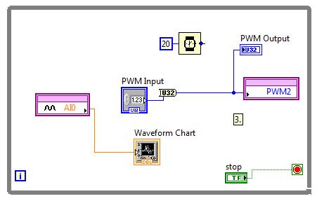
I'm trying to generate PWM with Laminary LM3S8962 signals.
At first, I thought that always the entrance of the PWM output is the ratio between the width of the pulses.
I connected to AI0 PWM2 and run this VI:
By changing the value "PWM Input" AI0 strangely varies
Hi Neil84,
Thanks for posting on the Forum of National Instruments.
Just to add some information about PWM with LabVIEW Embedded for ARM. Set you the divider in the properties of elementary school of e/s of the project? Here is some information pulled using LabVIEW:
«The PWM frequency is the inverse of the period PWM.» A 16-bit system clock divider controls the frequency. For example, if the system clock is 50 MHz, the lowest possible PWM frequency is about 760 Hz. If you need a lower frequency, predivide based on the system clock of time PWM. To change the predivider, click the basic I/o node in the Project Explorer window, and then select Properties. This property affects the dating: 0/1, 2/3, 4/5. For example, if you set the output frequency 4, you also set the output frequency 5 because the two outputs share a common time base. "
Thus, with a 50 MHz clock and a 16 - bit divider, you would get 50 MHz/2 ^ 16 = 762, and therefore the lowest frequency you can achieve (using the value of the divisor of 64) would be around 12 Hz. You set this value of divisor of the project for the e/s specific PWM.
Let me know if this clears up things or if you have additional questions.
Kind regards
-
Implement the Std::Vector < < Point2i > > Std::Vector in dll wrapper for LabVIEW
Hi, I'm writing a wrapper dll that using OpenCV function. I had been sucessfully implement Std::Vector
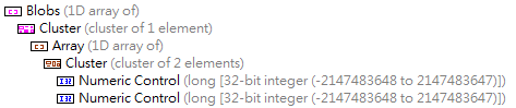
by referring to "An array of clusters to a dll C sending". And now, I want to implement the Std::Vector<>
> who is a lot like table 2D but each line items may be different. In LabVIEW, I attribute a range of cluster of the dashboard cluster of 2 I32 elements, structure which is shown below:
I think it has the same functionality as Std::Vector<>
> in C++. So I plug this data on the "Call library function node" structure and generate C code that indicated below:
/* Call Library source file */

#include "extcode.h"

/* lv_prolog.h and lv_epilog.h set up the correct alignment for LabVIEW data. */
#include "lv_prolog.h"

/* Typedefs */

typedef struct {
    int32_t elt1;
    int32_t elt2;
    } TD4;

typedef struct {
    int32_t dimSize;
    TD4 elt[1];
    } TD3;
typedef TD3 **TD3Hdl;

typedef struct {
    TD3Hdl elt1;
    } TD2;

typedef struct {
    int32_t dimSize;
    TD2 elt[1];
    } TD1;
typedef TD1 **TD1Hdl;

#include "lv_epilog.h"

void funcName(TD1Hdl arg1);

void funcName(TD1Hdl arg1)
{

    /* Insert code here */

}
Then, I write this code show below in dll wrapper:
void funcName(TD1Hdl Blobs) { vector < vector> blobs; // Distribute contents of blobs to Blobs from LabVIEW MgErr err = mgNoErr; size_t arraySizeInBytes = Offset(TD1, elt1) + sizeof(TD2)*blobs.size(); // Determine row size err = DSSetHSzClr(Blobs, arraySizeInBytes); if (err != mgNoErr) return; (*Blobs)->dimSize = blobs.size(); for (size_t i = 0; i < blobs.size(); i++) { arraySizeInBytes = Offset(TD3, elt) + sizeof(TD4)*blobs[i].size(); // Determine col size of each row err = DSSetHSzClr((*Blobs)->elt[i].elt1, arraySizeInBytes); if (err != mgNoErr) return; /*......................*/ } } When I call LabVIEW dll, the program get interuption(i.e shutdown) on line where I want to determine the size of each row.
Could someone give me some suggestions on this subject or promote another application of this requirement?
Thank you very much.MgErr funcName(TD1Hdl Blobs) { vector < vector> blobs; Labeling(image_binary, blobs); // the prototype of this function is: Labeling(Mat &binary, Vector Personaally I've usually done like this. Already, the tar of DSSetHSzClr() indicates if there was something wrong and that the handle cannot really become NULL to call this function.
To be entirely correct and safety integrated, you must do more than that. But as long as you assume that the incoming picture is always smaller that the outgoing Board will be (usually it be 0 items when you enter this function, but if you reuse sort table in the diagram, by storing it in a registry change for example, this may not be true more) this will be enough.
-
I want to control the speed and direction of a motor continuous using labview with pwm
I want to control the speed and direction of a motor (essentially a toy motor) continuous generating a PWM signal in labview. I'm using L293d motor and exit DAQ-9472. Can I do this without the help of any microcontroller but only a simple labview code and the DAQ 9472 output
There are many examples on how to generate a PWM on one in the buffer, or on a counter, but that does not support this card. A 8 a cDAQ chassis also a BNC connector that can be used as a counter as well. These examples can be found in help > example Finder in LabVIEW.
Also be aware of your current limiting. This card can drive a decent amount of current, but it has its limits. You'll want to put an inline meter to see what is current and see how far you get to it.
-
Run the Code Labview program on VN8970 vector material
I would like to ask if anyone has ever tried to run the Labview Code on the material vector in Standaone Mode,
The VN8970 have a PC as material and I would use as my hardware target.
Labview programming would go toward, creating / establishing a controller which output is POSSIBLE only.
Necessary sensor data is on the BUS CAN even output going to the CAN-BUS network.
The vector hardware box 8970 should run with the Labview code inside and be just like a car engine controller, just a BOX knot...
Can anyone shade some light on this topic because it is very difficult to collect all the required bits.
Vector support won't help with that because that intends it to sell their own software, which does not fit this need.
Far as I can tell the VN8970 has an ATOM processor or a core-i7 on board and running something called vector CANoeRT.
From the VN89xx Manual:
"The family of interface VN8900 offers a stand-alone mode that allows you to measure without any other PC user.
To this end that a request can be configured in the canoe, which is then written to the NVM of the VN8900. After a reboot, the configura-tion is loaded and the measure began independently. »
Canoe uses a programming language called CAPL. My understanding is that the code of the CAPL is downloaded on the series VN89xx materials and run directly on the device without the need to be connected to a PC.
In other words, I don't think there is a way to get a LabVIEW code to run on a VN8970.
The vxlapi.dll that is used here is intended to be used on a Windows operating system. You can use it to control the VN8970 similar to the other vector material, but not in standalone mode. I don't know what OS runs on the material of VN89xx but I doubt you'd be able to install a LabVIEW run-time engine on it.
I think your only option to run a VN8970 in stand-alone mode is to buy a canoe license that allows you to do and learn how to write the CAPL.
-
LabVIEW IMAQ: How to release a one-shot cushion of space
Hello
We use IMAQ version 14.5.0.
We have management problems of the buffer that IMAQ uses to store acquired images.
We are releasing a device of linear scan at very high speeds (~ 145 000 lines per second) using an external clock sent via the RTSI cable pulse.
In our LabVIEW program, we set up a list of ~ 200-element buffer and set the parameter of "Continuous?" to "One-shot", so that pads spaces will successively be filled by the camera and no data is lost. (We can't use "Continuous" or else the data is lost)
Then, we enter into a software loop where each iteration:
1. the device receives impulses clock ~ 200 to align the images ~ 200 (lines) to fill the list of buffers.
2. the computer retrieves images buffer ~ 200 sequentially and records the data elsewhere.
So we want to be able to fill repetitive the same list of buffer. The problem is, after the first iteration of the loop, "One-shot" buffer spaces are filled and may not be disclosed to the following iterations. So we end up 'extract' the images first ~ 200 over and over again, which of course is not useful.
We tried to release buffer using "Extract IMAQ buffer VI" spaces, by entering "-1"to "stamp out"." But nothing helped.
We looked at using "IMAQ dispose" of completely destroy the images and clear memory space buffer, then using "IMAQ Create" to make fresh buffer space memory. But we will have to do in each iteration of the loop - this is not practical, because we want to use the capabilities of the camera's high-speed.
Is there a method to "erase" a space of "One-shot" buffer for subsequent iterations?
A test version of our code is attached. Sync_Camera_v3 is the main VI.
I deeply appreciate someone has suggestions to our situation! Thank you.
-
Hello everyone.
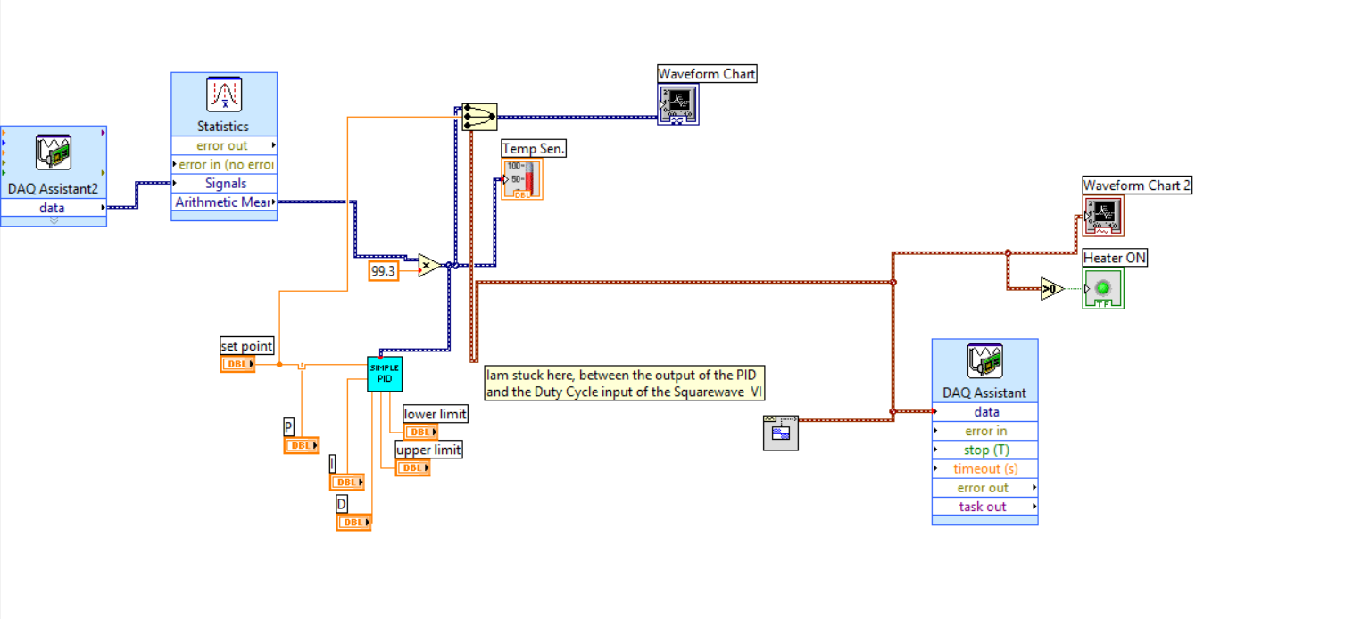
IAM working on a temperature of Labview control program that uses a controller of PDI, a radiator, a read thermocouple temperature.
IAM able to read the sensor and I think that I managed to implement the PID as well.
What I have to do now is to convert the output of the PID in a Cycle of use appropriate in % to enable/disable-energize a Solid State Relay for the power supply of heating.
To generate a square wave, I thought using the Waveform.VI of the place. (see image below)
The output for the PID is in the range 0... 5 v so I guess I do this output to scale in a way?
Thanks in advance for any help,
Best regards
Michael
I have not seen that VI PID single within a certain time, and if you have access to the PID toolkit (now included with versions of LabVIEW non-Base) you must use that one instead. In both cases, however, the limits of output are set by entries in the VI - in your case, the 'threshold' and controls 'Cap '. Change these so they are 0 to 100 and then use the output of the cyclical report.
-
Space required on target RT for LabVIEW Control design and Simulation
Hello
I want to run a DLL file on an RT target using LabVIEW Control design and Simulation, but I'm not sure of the required amount of RAM on the RT-target. My RT-target options are respectively cRIO 9002 and cRIO-9004 with 32 and 64 MB of RAM. Is this a sufficient amount of RAM to run the simulation? ¨¨
Thanks in advance
This will depend on the size of your dll, the size of the rest of the code, you can create other necessary drivers/modules, memory use when your application runs, etc.
9002 and 9004 have not a lot of RAM on them and the minimum software installation to run a control application Design & Simulation (CD & Sim) will take around 22Mo of it (the majority of RAM available to the 9002). It would be possible to run your application on these two controllers if you keep it small but it will depend on what you want to do.
Maybe you are looking for
-
remove the search box from about: newtab page
So, basically the same problem here: https://support.mozilla.org/en-US/questions/998430?esab=a & as = aaq With the exception of two major differences: 1. the solution provided in the above URL does not work. I tried to create the file in the appropri
-
How to get back to normal. F11 does not work. Don't have the bar menus or dock.
I went to the display of full backups. Now, I can't go back to the normal screen size. I don't have tools, menu bar or dock. Cannot click on anything. F11 is not working with Mac Snow Leopard.
-
Once connected to VPN, no noise and the display returns to Legacy Version
Hello I'm having a problem with my Windows XP Home Edition lose an output audio and returning to its display go back to a previous version. Scenario:-J' have VPN connect to my network to work and then remote desktop for my work machine.-After the clo
-
Office Professional 2007 - installation Windows XP
Bought the new Office Professional 2007 and installed on my laptop. Installation went smoothly, but am unable to activate due to an error message telling me I have an invalid product key. I uninstalled and installed twice with no success. Tried activ
-
Do you have Sony Z3 d6603 supports quick load 2.0 or 3.0