LabVIEW PID PWM controller
Hello everyone.
IAM working on a temperature of Labview control program that uses a controller of PDI, a radiator, a read thermocouple temperature.
IAM able to read the sensor and I think that I managed to implement the PID as well.
What I have to do now is to convert the output of the PID in a Cycle of use appropriate in % to enable/disable-energize a Solid State Relay for the power supply of heating.
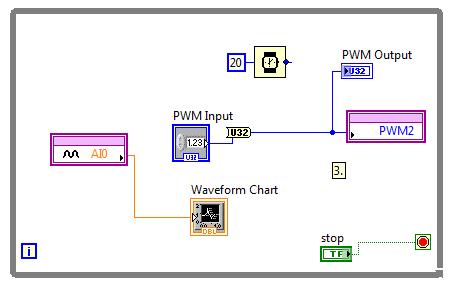
To generate a square wave, I thought using the Waveform.VI of the place. (see image below)
The output for the PID is in the range 0... 5 v so I guess I do this output to scale in a way?
Thanks in advance for any help,
Best regards
Michael
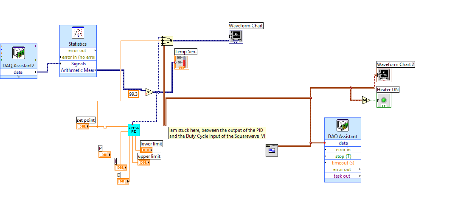
I have not seen that VI PID single within a certain time, and if you have access to the PID toolkit (now included with versions of LabVIEW non-Base) you must use that one instead. In both cases, however, the limits of output are set by entries in the VI - in your case, the 'threshold' and controls 'Cap '. Change these so they are 0 to 100 and then use the output of the cyclical report.
Tags: NI Software
Similar Questions
-
LabView PID control with PWM output and ramp / soak.
-
Hi all
I'm trying to generate PWM with Laminary LM3S8962 signals.
At first, I thought that always the entrance of the PWM output is the ratio between the width of the pulses.
I connected to AI0 PWM2 and run this VI:
By changing the value "PWM Input" AI0 strangely varies
Hi Neil84,
Thanks for posting on the Forum of National Instruments.
Just to add some information about PWM with LabVIEW Embedded for ARM. Set you the divider in the properties of elementary school of e/s of the project? Here is some information pulled using LabVIEW:
«The PWM frequency is the inverse of the period PWM.» A 16-bit system clock divider controls the frequency. For example, if the system clock is 50 MHz, the lowest possible PWM frequency is about 760 Hz. If you need a lower frequency, predivide based on the system clock of time PWM. To change the predivider, click the basic I/o node in the Project Explorer window, and then select Properties. This property affects the dating: 0/1, 2/3, 4/5. For example, if you set the output frequency 4, you also set the output frequency 5 because the two outputs share a common time base. "
Thus, with a 50 MHz clock and a 16 - bit divider, you would get 50 MHz/2 ^ 16 = 762, and therefore the lowest frequency you can achieve (using the value of the divisor of 64) would be around 12 Hz. You set this value of divisor of the project for the e/s specific PWM.
Let me know if this clears up things or if you have additional questions.
Kind regards
-
modulation toolkit for labview for embedded controller PXI-8106
Hello
I have an on-board controller: 8106 PXI OR PXI 5661 and 5671. He came with DAMA RFSG but not the Modulation Toolkit (TM). Now I cannot access some screws RF Toolkit as NI DAMA close.vi etc. I opened a code that uses this DAMA close.vi and since I donot have probably MT, I can't run since the claim code to choose the path!
I checked for the TM in the start menu-> all programs-> national instruments-> modulation but in vain. Also, I opened MAX and under "Software", I could find DAA, pilots RFSG etc but not the Mt.
When I checked online it says I have to buy the cd/dvd of MT. If I do, how I run on my controller? What are my other options?
PK
Hello
I think I solved the above problem. I had to install the RFSG and ACD for labVIEW. For some reason, the equipment was delivered to me with DAMA and RFSG, but only for C. This part was misleading because I saw on my National Instruments system but not the DAMA DAMA and RFSG vi. Also spectral measurement Toolkit (SMT) has not been installed. SMT is a MUST for the good functioning of the RF VSA. After you install the required drivers and tool boxes, I am able to run and use the VI completely.
Thanks for your support Abhishek.
PK
-
I want to control the speed and direction of a motor continuous using labview with pwm
I want to control the speed and direction of a motor (essentially a toy motor) continuous generating a PWM signal in labview. I'm using L293d motor and exit DAQ-9472. Can I do this without the help of any microcontroller but only a simple labview code and the DAQ 9472 output
There are many examples on how to generate a PWM on one in the buffer, or on a counter, but that does not support this card. A 8 a cDAQ chassis also a BNC connector that can be used as a counter as well. These examples can be found in help > example Finder in LabVIEW.
Also be aware of your current limiting. This card can drive a decent amount of current, but it has its limits. You'll want to put an inline meter to see what is current and see how far you get to it.
-
need help with an order first level using LABVIEW PID control process.
As the program begins to run the PV value also increase when it reaches the SP is not settledown instead it stops.
Have you tried on the NEST? There are a bunch of examples here on the forum
-
PID controller compatible LabView
Hi all
We have built an oven of automated test. It was decided that it is cheaper and more convenient to use a pre built the PID controller, however
our task is to set the temperature of the oven by using LabView code, so the PID should communicate with the computer.
I would be really grateful if you could give me a little advice if these controllers exist and where they are or it could be easier to use the box of DAQ + OR PID
box tools + with external power supply + heating element power transistor.
PS just to note, temperature range is not very high (20-200 ° C)
All the best
Alexander
Hi Alexander,.
When you talk about PID controller, there are two options:
1 software based controller PID (you can develop using the LabVIEW PID toolkit)
2. regulator based material PID... If you choose to have a PID of hardware in service, you must ensure that it can be used with LabVIEW, I know that what is your concern...!
For most of these PID regulators (hardware) are an instrument of series (RS-232, RS-485 or MODBUS based) and which can be easily integrated with LabVIEW... no tool is necessary, but all you need is VISA functions or MODBUS library.
-
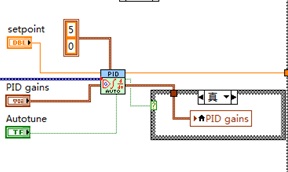
I want the controller PID Autotuning
I have a project of flow using on LabVIEW PID control.
So I want the controller pid autotuning and if possible then with manual and automatic mode switchable.
Pls see if someone can help me.
-
slowly decreasing oscillation for PID
In my project, now I am facing a very interesting problem, and I would like to ask the opinion of others.
I control the temperature of a phyiscal object using the LabView PID toolkit, with good results, I set my controller manually using the Ziegler-Nichols closed loop adjustment rule. The process value (PV) reaches the set point (SP) quick (about a year and a half period time and swing left), and I've reached the ultimate accuracy (deviation around SP) fast enough.
However, I realized that in fact, in my experience, a swing slowly decline would be beneficial at the beginning of the process because of certain physical phenomena.
I guess I should use some kind of hourly? For example, I would that my control system having an oscillation decreases with only 5% of amplitude in a period time.
All tips are welcome!

Kind regards
I think that the right adjustment of the values, you could get the controller for you to do. Try to increase the proportional gain - but do not forget that with the LabVIEW PID, which will also affect the gain full and derived, then you may need to set those too. You know, Ziegler-Nichols tuning approach, that there is a proportional gain during which you get stable sustained oscillations, so looking for a proportional gain below the ultimate gain which allows you the degrowth in oscillations that you want.
For more info on math, try a search on "rate of decay PID. Conventional tuning methods aim ratio of disintegration of a quarter - each successive swing has an amplitude of 1/4 of the previous swing. Looks that you want your controller tuned for a greater ratio decomposition, where each successive swing has an amplitude of only slightly lower than the previous.
Alternatively you could overlay a swing decaying about to set. This might be easier.
Gain scheduling is used when you want the different PID gains according to the set point. From your description, I think not hourly is a solution to your problem.
-
Gain setting NI LabVIEW RIO assessment Kit online.
Hello
I'm interested in using the evaluation package NI LabVIEW RIO for the implementation of a PID controller. I want to know if it is possible to adjust the gains PID controller implemented on this kit without putting an end to the operation in real time? If, for example, if the controller controls the speed of a motor continuous, can I adjust the LabView PID gains without having to stop the kit?
Umar.
Hi Omar,.
You ask about functionality to AutoFix or just tuning the PID manually? Whatever it is, you should be able to capture your PID non-stop kit.
-
How can I set a deadband for PID regulation
When I use a PID. VI to set pressure, when the PV nearby OAS, I want the PID.vi hold its output, but I have no idea to set the parameters of dead zone! (can not find the definition of dead zone)
An engineer PLC said that the dead zone is a common parameters PID, but idon't know not how to configure in labview pid!
Help, please, thank you!
You've already written that you have to do. A possible implementation is simply "freeze" the output of the PID controller. Use the "advanced version" of the screw of PID (normal or with automatic adjustment in case of need).
-
Manual of PID for transfer Auto smooth
Hello
I am using the PID command for a pump to ISCO syringe with manual Steplessly in automatic control, but I can't seem to make it work.
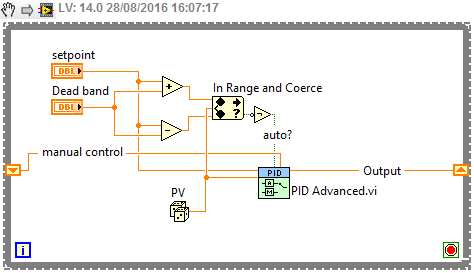
This shoot-syringe has an entry and exit pressure and is used to apply a force to keep the vertical movement of a constant of the sample. The amount of applied pressure is related to vertical displacement by an equation that appears in the attached VI. This VI aims to apply a variable force according to the displacement of the sample in order to try to keep moving 0.
Here is some general information on the pump that I use:
The pump is autonomous and can independently maintain pressure regardless of the LabVIEW PID controller. The pump only takes pressure of LabVIEW controls and maintain this pressure until another pressure control (I think that the pump integrated into the controller itself is a regulator PID.)
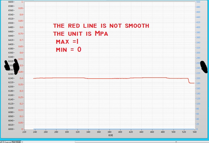
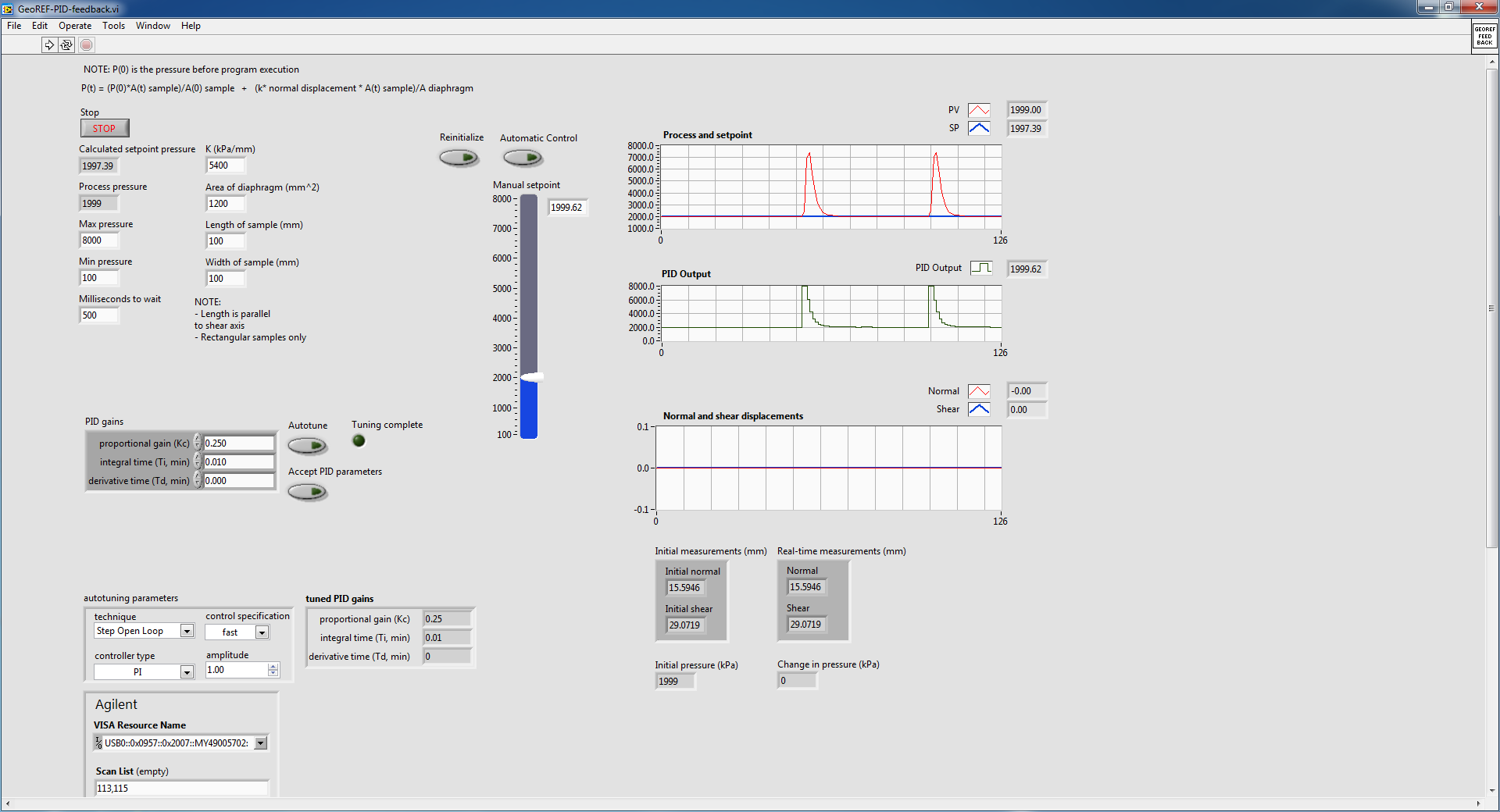
The problem I have is if I start the VI with the pump at a constant pressure (using the hand control with advanced PID VI) and crossing the wire to automatic control, the advanced PID VI immediately shows the pump to adjust the pressure up and then slowly bring it down to the steady state. This happens even if the hand control pressure is stable and identical to the auto set pressure. This following image details what I'm talking about:
The pump is in steady state, as shown in the diagram of pressure and the value in manual initially and then toggled mode on automatic control (designating the huge bump). I did it twice to show what happens when I go back. Manual automatic is without suddenly, because I used a local variable to constantly change the manual set temperature.
I did some troubleshooting and experiment and here are some of the results that I found:
1. when going from manual to automatic control, PID regulator sets the maximum pressure and then slowly bring it down to the set value
2 when it is cold from the VI in automatic mode with true to reset, the PID controller sets the pressure at a minimum and then slowly bring it up to the set value. This occurs even if the value of the original process is close to the set point (feed the actual value in the PID controller before execution also does not help.)
I also tried to play with the gains of PID in VI and found that if I turn off the 'I' and parameters "D" (together the two to 0), I no longer suffer from the huge bump, but the PID controller can bring the real set point value as there is always a lag.
I don't know if this is a result of bad PID tuning, but after the initial bump in the transition between manual and automatic, the PID controller seems to be able to maintain the correct pressure well.
The reason why I am using a PID controller rather send the pump controls (since it can independently maintain pressure) is because it is much smoother.
In the attached VI, there are a few side screws that are called that are specific to the pump and the LVDT used for detection of vertical movement. I do not think that they have an effect on why I don't get a transfer smoothly without jerking, so I only put comments to explain what they are doing.
I found another thread in forum with a similar question, but none of the solutions posted it seemed to have helped me. Here is the link to this thread:
http://forums.NI.com/T5/LabVIEW/PID-manual-to-auto-bumpless-transfer/m-p/3180609#M920098
Thank you.
Best regards
Victor
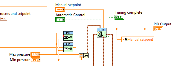
Your topology is not quite how we recommend that you make the transfer smooth. Can you do something like this?
Who will do manual setpoint pressure (units) and you need to update your gain, but it should follow. What is an option?
-
Command PID made al control of DC motors
Hola a todos
Alguien me could asesorar con el uso del PID toolkit there that manera lo puedo more al control of 2 DC motors, con doble cuadratura encoders
Buenos dias, Diego,
SIGA el enlace para descargar el PID Toolkit. Any pregunta por favor póngase in contacto con nosotros.
LabVIEW PID and Fuzzy Logic Control Toolkit 6.0 - update for LabVIEW 8.0 - Windows
http://Joule.NI.com/nidu/CDs/view/p/ID/603/lang/en
Carefully,.
-
Hi guys,.
Im a software using advanced LabVIEW PID and hourly programming. But as my gain change, the output does not accordingly with my gain. For example:
Error = 10
Gain = 10
Output = 100
Then
Gain = 0, 01
Output = 100 supposed to be output = 1
Looks like transfer smoothly? I couldn't tell.
Yo have any idea why? The VI of "PID Gain schedule example" change accordingly with the error output. But mine is not. I hope you guys could help

Not the Gain annex vi does not change your output according to the entry it will select all of the gains that you want to use. In a certain type of profiles, we will have to use a different set of earnings, so in these cases, you can have a different set of gains and which apply accordingly. For your business simple PID must be suffucient.
-
PID control with big delay in the process variable
Hello
My goal is to control the temperature via a valve and heat exchanger. I proceeded variable (temperature) measured from a hose. This temperature should be raised a few degrees with a heat exchanger. So basically I need to order a valve that allows the water to flow through the heat exchanger to raise the temperature to the desired level.
My original plan was to use a base PID regulation to operate the dispenser. However, it is about 0.5 to 1 minute of delay time in the temperature probe after I opened the valve, which increases the temperature. This leads to a situation where the PID regulation valve fully open during this period (trying to get the temperature rise). Then once the temperature begins to rise it fires quite quickly. PID begins turning the tap off almost immediately, but because of the time delay in the sensor, the temperature exceeds seriously. This led to severe oscillation and at worst unstable processes. I tried to adjust the PID control to "predict" the timer to close the valve in advance to minimize the excess, but failed.
I would appreciate if anyone has any ideas how to make this type of control with Labview PID functions. I also wonder if there is a better type of control procedure for this scenario as a PID control?
-Lars
This is a very common situation in the heating control, and generally PID can be adjusted to make it work. How do you do the tuning? If you do it by trial and errors, you have little chance to succeed. For a slow process with time delay, I like to use the method Cohen Coons, or similar open Ziegler-Nichols-loop method. The idea is that you temporarily remove or disable the PID. Set the valve in a fixed position and wait for the temperature to stabilize. Then, change the setting of the valve and record temperature at regular intervals data until the temperature is stable again to a new value. Use these data to get the initial values of PID using the equations provided by the tuning method you choose.
Maybe you are looking for
-
How etc. except chapters on a dvd?
share on dvd is possible but that? where and how can I learn how to make the menu and chapters etc. in the help and nothing about this. Thank you
-
External monitor closes on my Satellite A30
Hello I have a problem with the Intel extreme graphics double display driver. Whenever I have attach an external monitor (projector, screen...), it works very well for a while and then quits. Usually, but not always, restart computer help (laptop Sat
-
Do not disturb can be dangerous
Ago one Sunday morning, several months, I put the function do not disturb in my iP6 to 9-12 to hold the phone ringing during mass. Time funtion game (ON / OFF) was not the day of the week, weekend..., so I assumed it was a time of game that was set
-
I have a Pavilion G7 CNF1132K7T has an i3 processor and I have an i7. It is poosible with current motherboard?
-
I am running XP and I can't use my keyboard and Device Manager is empty.
I am running XP and I can't use my keyboard and Device Manager is empty. I also have problems with my other computer also running XP and it will only start in safe mode. I tried to restore, and when it restarts it still will not start normally. Help,