Space coordinate in LabVIEW
Hello
I use the getting started with NI 951 x Modules in the series C and LabVIEW tutorial and I can't seem to make it work. I followed step by step and when I clicked on run on the front, I got the following error. Error code: 70028
Linear displacement during the definition of the position [] on the test Section.
«"" "String of full appeal:»»"» I didn't create a 3-axis coordinate space and tutorial for two calls. I tried to remove one axis and by using only two, but that did not work. My diagram looks the same as that of the example except that I seem to have only a SINGLE coordinated in my system (notice down left the wire connected to the position [] has only one box coordinated instead of two as in the example). I tried to leave and the recreation of the coordinate axis and the VI with the same result. Am I missing something? It seems that my coordinate system appears in table 1 x 0 instead of a table 1 x 3 or something? I tried to restart the cRIO and start a whole new project, essentially from step 1 excluding the installation of the software on the cRIO. Please let me know if you have any advice or have had the same problems. Thank you Tags: NI Hardware Space vector PWM Labview (3-ph) Hi all I have a simple concept of triangular reference PWM. The program is simple in labview in Matlab Simulink. I need someone to help me if I want to draw SPACE VECTOR PWM. The attached VI is just a reference for you. How the calculation would be if I want to trace the reference voltage as vector. Thank you I don't know if it's a question of LabVIEW, or just a more general question, but in any case I'm stuck! A piece of equipment that we have just received the laboratory is a Geokon LC - 2 x 16 data logger , which is used to read in 16 (vibrating wire type) meters of the strain. Unfortunately, data acquisition comes with its own proprietary software, I still love to avoid if possible. The reason is that I have a lot of different pieces of instrumentation and I wish I had all the coordinates in LabVIEW for various reasons, but basically I just have more control and customization in this way. In all cases, Geokon software must be running in order to execute the Datalogger (caused by excitation of the strain gauges, communication, etc.). This software communicates with the data acquisition via a COM port. My hope was that I could just use LabVIEW to listen for traffic on that port and I was able to analyze the data as it came out of a "backdoor" to this type of solution. Once I have given, I can do what I need to do in LabVIEW and avoid other software entirely. Here's the problem though: If the software Geokon is connected to this specific COM port (i.e. COM 3), no other software can connect to this port simultaneously. I tried with LabVIEW and same Hyperterminal, or to not seem to work. Someone at - it an idea on how I could go about this? Cory, The manual for this contains all ASCII commands for configuration/control instrument. Should you need to create your own LV driver. I don't know how to use the method (PDDrawPageOrCosObjectToBuffer) in the Mac environment. Use the method of PDDrawPageOrCosObjectToBuffer of Acrobat SDK from DC () in the Mac environment, I want to get a screenshot of the PDF in the bitmap to the screen. A description of PDDrawPageOrCosObjectToBuffer () in Acrobat DC SDK API references, but I do not understand how to use the method. Please tell me this use. If there is a code example using PDDrawPageOrCosObjectToBuffer (), I'm happy. Hello My code is finally working with PDDrawPageOrCosObjectToBuffer. I hope it helps someone: void releaseBufferForCG (void * / * info * /, const void * data, size_t / * size * /) { Free ((void*) Data); } CGImageRef CAcrobatBitmapCreator::ConvertToBitmap (const PDPage & i_rPDPage, ASFixedMatrix & i_rTransform, int & i_rBitmapWidth, int & i_rBitmapHeight) { Get the rect in user-space coordinates update ASRealRect updateRectReal = {0,0,0,0}; ASFixedRect boxFixed; PDPageGetBBox (i_rPDPage & boxFixed); updateRectReal.top = ASFixedToFloat (boxFixed.top); updateRectReal.left = ASFixedToFloat (boxFixed.left); updateRectReal.right = ASFixedToFloat (boxFixed.right); updateRectReal.bottom = ASFixedToFloat (boxFixed.bottom); Convert the fixed transformation matrix to real ASRealMatrix transformReal = {0, 0, 0, 0, 0, 0}; transformReal.a = ASFixedToFloat (i_rTransform.a); transformReal.b = ASFixedToFloat (i_rTransform.b); transformReal.c = ASFixedToFloat (i_rTransform.c); transformReal.d = ASFixedToFloat (i_rTransform.d); transformReal.tx = ASFixedToFloat (i_rTransform.h); transformReal.ty = ASFixedToFloat (i_rTransform.v); ASRealRect destRectReal = {0, i_rBitmapHeight, i_rBitmapWidth, 0}; l, r, t, b Prepare the buffer for drawing https://forums.adobe.com/thread/1850089 This first call to PDDrawPageOrCosObjectToBuffer is only used to get the size of the buffer. ASCab flags = ASCabNew(); ASInt32 bitsPerChannel = 8; ASUns32 bufferSize = PDDrawPageOrCosObjectToBuffer (i_rPDPage, CosNewNull(), ASAtomFromString ("DeviceRGB"), NULL, NULL, bitsPerChannel, flags, 9, NULL, & transformReal, & destRectReal, & updateRectReal, NULL, 0, (NULL); char buffer = (char *) malloc (bufferSize); Memset (buffer, 0xff, bufferSize); Draw in the buffer ASCabPutBool (flags, kPDPageUseAnnotFacesStr, true); ASCabPutBool (flags, kPDPageDrawSmoothTextStr, true); ASCabPutBool (flags, kPDPageDrawSmoothLineArtStr, true); ASCabPutBool (flags, kPDPageDrawSmoothImageStr, true); bufferSize = PDDrawPageOrCosObjectToBuffer (i_rPDPage, CosNewNull(), ASAtomFromString ("DeviceRGB"), NULL, NULL, bitsPerChannel, flags, 9, NULL, & transformReal, & destRectReal, & updateRectReal, buffer, bufferSize, (NULL); Convert buffer CGImage // 1. Remove the 4 bytes of padding at the end, in a new buffer. size_t bytesPerRow = (i_rBitmapWidth * 3); bytesPerRow = (bytesPerRow % 4 == 0? bytesPerRow: bytesPerRow + (4-(bytesPerRow % 4))); size_t bytesPerRowForGC = i_rBitmapWidth * 3; size_t bufferCGSize = bytesPerRowForGC * i_rBitmapHeight; char * bufferForGC = (char *) malloc (bufferCGSize); Memset (bufferForGC, 0xff, bufferCGSize); for (int lineIndex = 0; lineIndex)< i_rbitmapheight;=""> { char * destGCPtr = bufferForGC + (lineIndex * bytesPerRowForGC); char * srcPtr = buffer + (lineIndex * bytesPerRow); If ((srcPtr + bytesPerRowForGC)<= (buffer="" +="" buffersize)="" &&="" (destgcptr="" +="" bytesperrowforgc)=""><= (bufferforgc="" +="" buffercgsize)=""> { memcpy (destGCPtr, srcPtr, bytesPerRowForGC); } on the other { break; } } // 2. Create a CGImage using the new buffer. CGDataProviderRef provider = CGDataProviderCreateWithData (NULL, bufferForGC, bufferCGSize, releaseBufferForCG); Buffer are ions released this reminder Space color CGColorSpaceRef = CGColorSpaceCreateDeviceRGB();
CGImageRef finalImage = CGImageCreate (i_rBitmapWidth, i_rBitmapHeight, bitsPerChannel, bitsPerChannel * 3. bytesPerRowForGC, color, space kCGImageAlphaNone, provider, NULL, / / decode (of remapping the colors) true, / / interpolate (pixel smoothing) kCGRenderingIntentDefault); CGColorSpaceRelease (colorspace);
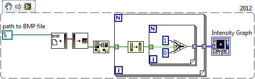
CGDataProviderRelease (provider); Free (buffer); FinalImage return; } David Creating and adding an annotation to a tour page Hello I write a plugin that will add a FreeText annotation normal to a page, near the top right corner of an existing link annotation to indicate the destination of this annotation to link page. My existing code works fine in most situations: I create a PDAnnot using PDPageCreateAnnot(), passing its bounding box, set its content by using the keys PDTextAnnotSetContents, RC CosDict, DS and DA, then add it using the PDPageAddAnnot() function. The situations that I have a problem with is when the page is turned (pages are usually scanned in and then turned as required), similar to the problem that is described in this discussion: http://forums.adobe.com/thread/851038, namely that the annotation is also shot, such that it is created in user-space coordinates. I set the pdAnnotNoRotate flag and it seems to work properly (apart from the location is still the user coords), until my desire of users to move or resize the annotation, as the bounding box with the sizing handles displayed always shot with the page and the only clickable part is at the junction with this box and the annotation. It may be a bug in Acrobat. Suffice it to say, pdAnnotNoRotate don't help me much. To remedy this, I have now to transform the bounding box to hold account of the page rotation using a combination of PDPageGetDefaultMatrix(), ASFixedMatrixInvert() and ASFixedMatrixTransformRect(). This concludes the correct bounding box, except that now I don't know how to rotate the contents of the annotation in the same way. I can't find the key turn mentioned in the thread linked to above, and the definition of the matrix on the appearance stream requires that the annotation has made an entry in the key to the AP, which is not after the creation from scratch. Create my own flow of appearance seems like a terribly difficult task when I really want to use the appearance by default anyway, just turned. My questions are: can someone tell me which section of the PDF reference covers the aforementioned key of 'Rotation '? If not, can I get a flow of appearance by default to add annotation and running? The key to the AP seems to have filled after that my job has run, because if I browse the PDF structure using preflight, new annotation indeed doesn't have a flow of appearance in the key to the AP, but this isn't immediately after creating or adding to a page. Perhaps there is another method to add an annotation properly rotated to the page? Thank you, Andrew I had the time to look at this issue again today and fixed the problem by setting the dictionary entry turn on the annotation to the same value as the rotation of the Page; the framework encompassing was calculated using the matrix by such default as mentioned in my original post. This demonstrated the annotation with the appropriate rotation. The key turn mentioned here does not seem to be documented (at least not in section 12.5.2 reference PDF - Annotation dictionaries), but I guess it's quite safe to use because it's the method that acrobat uses to place a FreeText Annotaion rotated correctly on a tour page. I am sure also that the NoRotate flag bit has not been set because of the problems mentioned above. It is not too much trouble to recreate annotations If the page is turned. In time real PXI-1031 does more work with labview. "Not enough disk space to perform the backup. The labview real-time project was working until a few weeks ago and the only error that is displayed on the PXI is this error message. "NEITHER Configuration Manager: not enough disk space for the backup" everything before that looks like it starts very well. Recently, I removed the hard drive and remove the 4 GB network log file because it seemed to me that a file of 4 GB on a fat32 file system was probably the cause of the problem. After that it the project worked when I tested it, but others in my lab said it was broken again the next day. Any help would be greatly appreciated because I don't know all that equipment. I found that I had "reset IP" set to "yes" in the bios that seemed to be causing my problem because I changed it to no and it seems to work perfectly now. Sorry that it took so much time to understand and I feel like a fool. Conversion of coordinates to screen coordinates of part of LabVIEW Hi all. I have a reminder of .NET that returns percentages of screen which I want to convert them into LabVIEW Panel coordinates. The goal is to have an indicator move to the right in the LV Panel coordinates when the .NET event fires. The management of the events is supported, but I have a problem with the math converting the percentage of the screen in an accurate position on a glass of LV. The first thing I did is to multiply the percentage by the resolution of the screen, but I'm stuck on how to take the screen pixel data and understand where it is compared to the part of the LV. I'm sorry if this was not the message more clear, I'll try and clarify any questions if I can. Thank you very much for your support. By specifying the screen coordinates in printf using LabView RT 2009 According to the 2011 help in LabView documentation 'Printf (Manager of LabVIEW function)", the character of the conversion of 'q' is supposed to refer to a point. The actual help text is "q Point (passed by value) as %d, %d, representing the coordinates horizontal, vertical. It is a valid conversion for LabView RT 2009 character? If so, then someone has an example of using these characters to print at line 10, column 1 on the console? I tried a lot of combinations like: printf ("% dqTest Row", (10.1)), etc. LabVIEW Real-time has not intrinsically a "console" - it has an "output stream. There is no API added to allow you to jump all over the console in native mode (don't cross the streams) - you can't even do it with the functions of Manager of LabVIEW (literally, it prints a point in this place of pixel, not text). Now, I tell you this, but if you happen to have a target with a video memory (like a PXI system, certainly NOT a cRIO or PCP) and you happen to know the address of where the video memory is on your Of course, I don't condone this and it is certainly NOT taken in charge (and only works on targets based on the PharLap with a video console), but there is a lot of fun. -Danny Hello everyone is it possible to tell me how I can make program in labview that take black and with image pixels and give the coordinates of black or white pixels again to me. It depends on the image and the module LabVIEW available to you. LabVIEW can open bitmap and png files and convert them into tables: if it's really a monochromatic (depth of 1 bit) you get a table 2D boolean, T for white, F for black. Just look at the index of the item to its details (don't forget that LabVIEW does not use the order of rows and columns, so you must transpose and reflect the table). If you have a 24 bit bitmap, the table will contain the color in hexadecimal synthesis (000000 for black, FFFFFF is white and so on); Yet once, you simply check if the element of the array correspond to your requirements and get its index. With the vision that you module con open other pictures and perform advanced on them without convert them into tables. Anyway, you can just type the extension of your image using LabVIEW and see what you get. Here is a code snippet to open a monochromatic image LabVIEW IMAQ: How to release a one-shot cushion of space Hello We use IMAQ version 14.5.0. We have management problems of the buffer that IMAQ uses to store acquired images. We are releasing a device of linear scan at very high speeds (~ 145 000 lines per second) using an external clock sent via the RTSI cable pulse. In our LabVIEW program, we set up a list of ~ 200-element buffer and set the parameter of "Continuous?" to "One-shot", so that pads spaces will successively be filled by the camera and no data is lost. (We can't use "Continuous" or else the data is lost) Then, we enter into a software loop where each iteration: 1. the device receives impulses clock ~ 200 to align the images ~ 200 (lines) to fill the list of buffers. 2. the computer retrieves images buffer ~ 200 sequentially and records the data elsewhere. So we want to be able to fill repetitive the same list of buffer. The problem is, after the first iteration of the loop, "One-shot" buffer spaces are filled and may not be disclosed to the following iterations. So we end up 'extract' the images first ~ 200 over and over again, which of course is not useful. We tried to release buffer using "Extract IMAQ buffer VI" spaces, by entering "-1"to "stamp out"." But nothing helped. We looked at using "IMAQ dispose" of completely destroy the images and clear memory space buffer, then using "IMAQ Create" to make fresh buffer space memory. But we will have to do in each iteration of the loop - this is not practical, because we want to use the capabilities of the camera's high-speed. Is there a method to "erase" a space of "One-shot" buffer for subsequent iterations? A test version of our code is attached. Sync_Camera_v3 is the main VI. I deeply appreciate someone has suggestions to our situation! Thank you. Find the child's location in the coordinate space of the parent I created a map of the counties of Montana. Each county is an MC inside separate the largest parent movie clip (allcnt_mc). When the user clicks on a County, I would like to focus this country on the scene and the zoom to its measurement. The hard part has said the parent (allcnt_mc) where the tween to. Given that each individual County is a child of the parent, they have their own coordinate space with reference to the parent. Is there a way I can query the location (x, y) of a child in the coordinate space of the parent? With this issue, I could calculate the distanct between the point of current regulation of the parent and the child, indicating the distance that the parent will have to move to focus on the scene. I tried to use localToGlobal but could not understand how to use it. var pt:Point = new Point (parent.child.x, parent.child.y); PT = parent.localToGlobal (PT); PT now has the parent.child coordinates in space of the parent coord. Space required on target RT for LabVIEW Control design and Simulation Hello I want to run a DLL file on an RT target using LabVIEW Control design and Simulation, but I'm not sure of the required amount of RAM on the RT-target. My RT-target options are respectively cRIO 9002 and cRIO-9004 with 32 and 64 MB of RAM. Is this a sufficient amount of RAM to run the simulation? ¨¨ Thanks in advance This will depend on the size of your dll, the size of the rest of the code, you can create other necessary drivers/modules, memory use when your application runs, etc. 9002 and 9004 have not a lot of RAM on them and the minimum software installation to run a control application Design & Simulation (CD & Sim) will take around 22Mo of it (the majority of RAM available to the 9002). It would be possible to run your application on these two controllers if you keep it small but it will depend on what you want to do. Choose and place using labview and or vision acquisition Hello world I'm doing a project studying on Vision guided pick and place of a robot (abb) industrial. I would like to know the steps involved in the creation of the block. I locate the object, move his webcam cooordinates. Then made a pattern match, and would send the cooordinates to the microcontroller. then from microcontroller for control of robot... then the industrial robot should choose the object and place it in a predefined area... I would be extremely grateful if you guys can help me because I am new to LabView. Thank you Pradeep.M What you describe is quite complex, but here are a few tips. The key is to establish a correlation between the coordinate system of the robot to the coordinate system of the camera. I guess that the camera is statically located above the pick-up area? I move the robot at each corner of the frame to its choice position vertically and note the position of the robot at these locations. These 4 points in space will be correlated to X, coordinates of pixels in the camera image. Basically, you need to write a sub - VI with entries being pixel X and is coordinated and coordinates output being the robot. Writing a test application saying the robot to get pixel location to any X, Y in the framework to test your Subvi. If this does not work, then you need to set up a correspondence to the model. You probably want to do a geometric pattern match. Take a look at this example: http://zone.ni.com/devzone/cda/epd/p/id/5555 You will need your pattern match algorithm to return both the coordinates for your robot, and the orientation of the tool needed for good pick up the object (if the pick-and-place robot tool requires to be in a specific direction). If it's basically up to you will convert the object X, Y and rotation angle in the framework that you receive correspondence from model to any coordinate system, the robot uses. The placement algorithm could be simply an adjustment of orientation to the object being investment and then investment positions could be an array of coordinates of robot which you browse after each pick. Be sure to implement security mechanisms in your algorithms so that the robot can never go somewhere outside of a safe range of coordinates. Allot of extra RAM for LabVIEW Hi all I'm out of memory trying to compile a great personality FPGA VI. LabVIEW generates an error and crashes when it reached the limit of 4 GB memory while generating intermediate files (specifically step 3/5). I have 8 GB of RAM installed on the laptop. I know that only 4 GB can be used by LV 32 bits, and it doesn't have a 64-bit version of LV FPGA. Does anyone have a solution or workaround for this? Decreasing again the size of my VI is not an option. I wonder if it is possible for compiling Xilnix itself of tools to access more memory? Mitch I don't think that would compile a project that includes only the FPGA VI. My project includes only the items that are needed to build the bitfile: DMA FIFO read & write, a global variable sub VI and two other sub screws, which are used in the FPGA VI. In my view, that a key issue, it's that it handles many groups that are up to 64 elements each. I took care not to include functions that take a lot of space on the FPGA, avoided constraint, etc., but the large paintings are an essential component. Yes, the Xilnix program itself is short of memory. If I remember correcly, the compiler showed the error message "a Xilnix request has run out of memory...". "and he said that 4 GB of RAM has been reached. I get to the conclusion that I have to wait for a 64-bit version of LabVIEW FPGA to be released (with a 64-bit compiler) to build the VI in the desired way. LabVIEW Communication Design Suite (size of the installation) Hello Can someone tell me how much space Labview Communication Design Suite (trial version) requires for installation and for how long can I use evaluation version of Labview Communication Design Suite. Thanks in advance. Hi Joseph,. The required disk space are in the readme file. These requirements will not change if you are just evaluating the software. The evaluation standard for all software period of NOR is 7 days, but can be extended for another 45 days as described by this KB. Since arriving in a new home, my printer wireless not working wireless Original title: prnter wireless Questions I have a wireless all-in-one lexmark x 4650 printer. Currently, we moved and had to changed internet service providers and now my printer does not print wireless... what should I do to get the printer to pic I am infected with the rustock.d virus, like a way to remove this thing without having to buy a specific product to do. Free running ANG HP Deskjet F4283 does not not on new MacBook Pro Hello I have a HP Deskjet F4283, I have used successfully and without any problems on my previous MacBook. I have recently replaced the computer with a new MacBook Pro, installed the software of the printer, but for some reason any that it does not w I am eager to implement the ability to send faxes via my computer instead of going to the fax machine, located in another room. This fax machine is a network printer/fax - Sharp B402SC MX to be precise. I tried to go through the steps with the netwo Hello IAM using dell inspiron n5010 Lapop who came from Windows 7 Home Basic... I could not find my product key during that... later I installed trial windows 7 ultimate... so far I'm used it... now, I would like to install pre installed win 7 Home b
The resource is not large enough to perform the specified operation.
nimc.getLastErrorOnInterface.vi
nimc.fb.straightLineMove.startStraightLineMove.coordinate.modeAbsolute.0.vi:1
Straight line move 2. VI
Similar Questions
#include

//calculate the stage's center
var stagecentx:Number=stage.width/2
var stagecenty:Number=stage.height/2

function tweento(e:MouseEvent):void{
     // the first two variables are referncing the county that was most recently clicked on
     var calledx:Number=allcnt_mc[xmlData.row.NAME[e.currentTarget.ivar]].x;
     var calledy:Number=allcnt_mc[xmlData.row.NAME[e.currentTarget.ivar]].y;
     // these variables represent the current location of the stage
     var allcntx:Number=allcnt_mc.x;
     var allcnty:Number=allcnt_mc.y;
     //  I'd like to then tween the allcnt_mc to the location of (calledx,calledy)
     //  but in the coordinate space of allcnt_mc
Maybe you are looking for