Specific setting Thermocouple Type block diagram
Hi all
I have an example VI that I play with. I would like to remove the thermocouple on the front screen selector and just set the DAQmx block as a K-type entry, because I K types. How can I do this?
Or all simply right click on the device and select 'change to Constant '.
You can learn a lot by clicking on objects and options display.
Tags: NI Software
Similar Questions
-
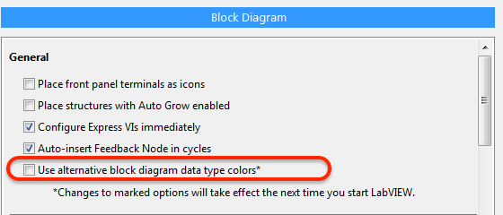
Use the colors of the alternative type block diagram data?
Options window 2016 LabVIEW to offer this new option:
The help file, however, is not the document, and I have been unable to find anywhere in the options window where the data type of alternative block diagram colors could be defined.
Any explanation would be welcome.
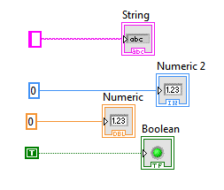
I drop everything possible, but decimal color seems to be certainly changed, and it seems that the real colors have changed, too. I'm color blind, so am not sure if the other fundamentals have changed.
Option:
Option ON:
-
In LabVIEW 2010, I have a Def Type control i.e. a Cluster with several other controls within the Cluster. Apparently, the references to the controls in the block diagram are based on the order that the controls have been added to the Type definition command. The side effect of this is that if a control is removed from the command of Type definition, many of the done Variable reference in the block diagram or now either broken, or worse still, refer to wrong control in the Type definition. These problems are quite difficult to find and fix.
Comment: If you create a control of Type definition and make a Cluster. Now add any controls to the Cluster in an order, let's say A, B, C, D. Their types does not matter. Now use the Type definition in one or more controls on the front panel. In the block mark references to controls inside the Type Def would control on FP. Now return to the Type definition and remove the command B of the definition of Type. Now, lots of errors appear. Broken links. But worse still, you see old references to B that now refer to C and old references to C are now referring to the old references to D and D are removed altogether, etc.. This side effect is much more errors, broken links and misreferences than expected otherwise.
How add and remove controls anywhere in a Cluster in a Type definition, at will, without creating a whole bunch of errors in program, broken links and misreferences for controls in the Type definition that have not changed?
-
Is any way to put a VI that I placed on a palette in the menu functions to create a copy of it self when I place it on the block diagram?
My example is as follows. I create a palette for a messaging configuration. The 'send message', 'message' and so forth will work normally with just called when necessary. But 'Create queues messge' must be specific for each instance, because I'm going to create a different number of queues each time I use it. (See system messages in queue OR for the "Continous Measument and Logging" model).
So every time I drag and drop that VI (Create message Queues) in the palette, I want that it ask me where I want to save the VI.
Is this possible?
See you soon
Henrik
There is always the file-> new... that opens a new window. You can have your models in this window by putting them somewhere (I can't remember where at the moment).
-
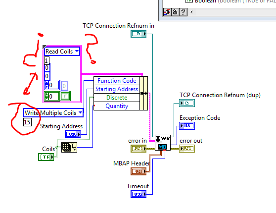
What this block diagram?
Match a VI Modbus Library. But I have because if the block is configured to write multiple coils in the coils because reading is set to 1?
All this work?
Sorry if the question is a beginner.
In this block diagram, 'Coils Read' and 'Write multiple coils' are enumerated values (or possibly ringtones of appeal, which is not serious for the purpose of this explanation). Enumerations assign names to numbers, to make them easier to read. The coils Read command is set to 1, the command to write multiple coils has a value of 15. You don't need to worry about this number, however, because the enumeration takes care of it for you.
The constant cluster containing coils of reading is there just to provide the correct data type (a cluster with the right items). Almost all the elements of the latter shall be replaced by the values of wired in the Bundle to node Name. For example, the value of reading coils is there as a placeholder for any function Code. the actual Code of the function is defined by plugging write multiple coils in Bundle by name.
-
How to find the thermocouple type progromatically
Hi all
Is there a way to progromatically get the thermocouple set channels type? I ask because I want to write the type of thermocouple in my diary of PDM. I suppose that if possible it is a function of property node, but I can't.
Thanks for any advice.
The property you are looking for is the Analog Input: temperature: Thermocouple: Type in the DAQmx channel property node. If you do not, maybe because it's a specific property to the device, so you must configure the filter of the node property setting to display all the attributes or select your specific device that supports a thermocouple input
-
Reading of Thermocouple Type K with myRIO
I have a myRIO (room only) and I need to read for an internal PID K type thermocouple measures. I am able to do this directly in the room? Or I need an adapter?
Be as specific as possible.
Thank you.
The above listed connector is the connector for the card myRIO only.
In addition, the thermocouple type k has a + and - sign. If the + needs to go to one of the analog inputs and - needs to go ALWAYS, analog ground. See page 5 of the below myRIO 1950 manual for the pinout of the connector.
-
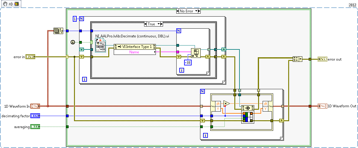
I have a double 2D chart I want to decimate continuously using the ".vi (continuous) Decimate" located in the range of Signal Processing. This VI is set on reentrant preallouee clone because it uses a FGV to save the State of the call to. What I could do, but do not want to, is having a huge index table and wire 20 + 1 table of DBL to 20 + unique VI instances decimate to ensure that each have their own data space and no 'cross-talk' doesn't happen, then 'picture of generation' all back after the fact.
I'm almost certain, there is a much cleaner way to do it with only one instance of unique block diagram of the VI decimate using techniques of the call by reference. I found my way to this link: Preallocated-Reentrant-VI-within-Parallelized-For-Loop that talks about something similar. After reading pages of four and the detailed help about the function 'Open VI référence' my head is spinning again on what option I want to spend (0x08 or 0x40 + 0x100) to ensure that whenever a slna 2D table come in, each of them is decimated by using the same clone that was used the last time it was called.
Although the DBL entry 2D array always has the same number of lines, now, it is not always in the future this number and ideal would not force me to create several references strictly typed in VI decimate that will have to change as grows the number of rows in the table 2D static DBL.
Anyone ready to set up an example VI that takes an array 2D arbitrary of DBL as input, decimating each line using the same clone independent of the "Decimate (continuous) .vi" and outputs the newly decimated 2D Array of LDM? Assume that each line uses the same factor of decimation and 'Sprawl' set to False.
Necessity is the mother of all invention and since it upsets me when I read a post that has a similar problem with no resolution, I felt compelled to post mine here. I'm sure it's better I can do within the current state of LabVIEW. The only question I have is what happens if I put the call by reference for loop be parallelizable? That trash completely the nature of 1 to 1 of what I intended?
-
Is there a way to tell if the block diagram is open when a VI? I have a Subvi, which is defined in modal when it is opened. When troubleshooting, if I run my application, but forget to disable modal for the Subvi forcing the system to lock upward.
It would be nice if I could set the property of the VI not be modal if the schema has been opened.
Any suggestions?
I would try to do several things:
1) go to the properties of the VI > appearance of window and click on the Customize button. From there, uncheck the box for "see the front when it is called.
(2) when the VI starts, read the 'Front Panel Window.State' VI property - this will tell you if the window is already open, (IE, if the window is open, the State of the window will be 'standard', "Increased" or "Reduced"). Note: This is the visibility of the front, not the block diagram
(3A) if the VI is not already open, set the 'Front Panel Window.Behaviour' property to modal and then open the front panel by using the node to invoke VI of "Front Panel.Open". It's basically imitating the behavior you describe this moment.
3 (b) if the VI is already open, set the property to the default or floating behavior to allow you to click other windows.
(4) when it is finished, if the VI is not already open, close it manually using the Panel.Close before invoking node (if it was already open, leave it open)
I've attached a screenshot of that sort of thing. I hope this helps.
Shaun
-
Block diagram of... block diagram
Hi, I need your help. IM the wrong person for this post, but I have to do, so I depend on your help. I need to explain how LabView (pasted below) program works, but I don't understand it myself
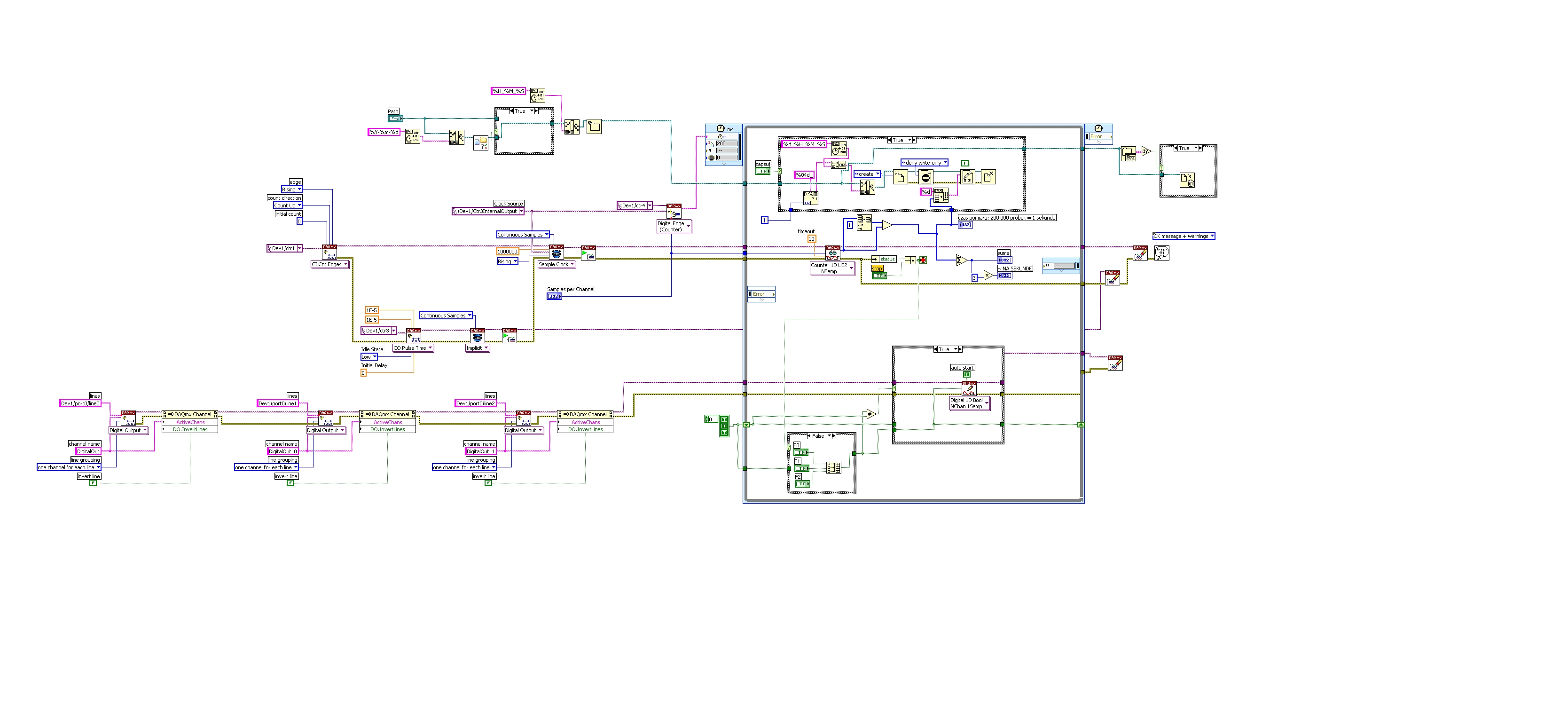
 I would like to ask if someone can create a simplified block diagram of the pattern-block LV I paste it here. I appreciate all the help and please take considaration I am short on time
https://DL.dropbox.com/s/yd10z7yorxvbzux/LVdiagram.jpg
It is a counter. Meter of photons to be exact.
Hi, Rodolphe,.
I will try to explain briefly what is this application:
Following materials may help you understand the underlying concepts:
http://www.NI.com/PDF/manuals/371022k.PDF
It is the manual of series M - chapters 6.7 and 8 explains how digital lines, meter and what is a PFI.
When you open the block diagram of your application, you can see several branches ranging from left to write.
The first one on the top is to create a path to a file. This path will be used to write data to a binary file. The data represent the number of impulses which can be counted as edges rising a signal connected to the meter to 1. This information CA be read if you follow the logic on the second branch from left to right, where the first VI is CI INT edges (edges of counter), and it will count up, on a rising edge of the signal connected to CTR1.
Later, there is another task created for counter 3, that generates impulses. The pulse seems to have 10uS length and 50% duty cycle. The signal generated by this counter is used as sample clock for measure and 1 meter. In addition, the same meter signal 3 will be used by 4 meter from the digital dashboard and create a clock which will clock the timed loop. Basically, the frequency of the timed loop is given by the task on 4 meter which counts pulses generated with meter 3.
The 3rd branch from left to right, creates three tasks on three outputs digital: Line 0, 1 and 2 where it is controlled by three buttons F0, F1 and F2. Basically, your timed loop will be a specific iteration, and every iteration buttons will be read and will be updated to the specified digital output above.
Whenver there is a mistake or the button is pressed, your application stops and closes the binary file and dealocate resources used.
I invite you to also look in the above manual.
Best regards
Ion R.
-
Outline of the block diagram flashing red
Hello. I don't have access to the Vi in question at the moment so I'll make it as General as possible. My Vi worked properly for a week or two, but today it started to flash red around the edge of the block diagram. Once the Vi makes the block diagram whole black for a while, followed by the red square around him. What is this red box? They are still able to run the Vi, it's why I can't stop their however, it is not a display of alarm or anything like that. I tried to watch as they run, but am getting no where fast. I just want to know what means the flashing red box does not pinpoint the problem. Thank you
This means that your chart has been set to a big "breakpoint." Go to View > breakpoint Manager and delete the offending breakpoint.
If you hold down the CTRL key while running a VI, LabVIEW adds a breakpoint at what you click on, so just be careful with that. I accidentally added breakpoints to my code more than once.
-
Hello
I do a charge battery discharge cycle using labview 2011... On the block diagram, I using node of the formula to change the operation of discharge of charge when the battery reaches a certain level, the battery is connected to the entry DAQ assistant... but when I connect the wizard entry to the formula node DAQ, an error pops up...
Block diagram errors
-You have connected two terminals of different types.Details
These can be wired together as their data types (digital, string, array, cluster, etc.) do not match. View the contextual help window to find out what type of data is required.
The type of the source is Dynamic Data.
The type of the sink is a double [64-bit real (precision ~ 15 digits)].Please help me...
You have incompatible data types. You need convert the data type to express dbl
-
How to find the position of the VI icon currently run on the block diagram of the appellant
Dear forum,
I am currently trying to use a LabVIEV VI as a simple sequencer: several (very slow) actions must run one after the other. Each action is represented by a Sub - VI, some actions are executed several times. My task is to view the Subvi somehow executing.
My first intention (just manipulate the icon of the VI running with 'Icon.Get VI as Image data' / 'Icon.Set VI of Image data' invoke nodes) has failed, because it changes all instances of the VI icon. If you use the same VI several times, all these VI icons are changed (see here: http://forums.ni.com/t5/LabVIEW/How-to-change-animate-icon-of-currently-running-VI/m-p/3120754/highl... )
My current approach is to use an image of the block diagram (with "VI: block diagram: get resized Image ' call method) in a picture of the front panel control and working within this control. But for this I need to know the position of the icon of the VI running. I know that I can assess the limits and Position via the properties GObj, but how to find the VI running (note that a VI can be installed several times on the block diagram, so the name of the VI is not unique)? IMHO the easiest way might be if a VI might find its icon on the block of the appellant diagram itself when it is run...
It is clear that this position is not yet the position on the photo, but this conversion is a small piece of work...
Kind regards
cpschnuffel
-
LabVIEW block diagram icons became invisible
I'm a bit of a loss here.
I worked on a fairly large vi of higher level for a while when suddenly several vi system developed display problems. In particular, all the screws of the FPGA module no longer appear on the block diagram. They are there, because I can move the properties and thread them, but they are invisible. Even if I add a new menu, it is invisible. Is the same for the control on the structure of timed loop block. The loop is visible, but the controls are not.
I have attached a picture of a part of the vi that shows what should be a 'open FPGA reference' and a timed loop. As you can see, the wires are connected and it compiles and works very well, but there is nothing on the screen
It is specific to this vi. If I create a new vi and add the same vi they look very well. As far as I know, I did not change to any display settings.
Any suggestions?
Hi Nathan,
You should be able to get a global position by moving one of the scroll bars. When you click or drag the scroll bar a small box should appear (right of the cleaning if the BD is enlarged or below the bar of horizontal scrolling if the BD is is not maximized) giving the global coordinates. If you find that you are outside about 15000 pixels (I don't know if it is a hard cut) are trying to move close to the origin.
You should not recreate anything. Actuall you can find the line where the icons become visible. In a quick test here he looked about 15000 pixels.
-
area limit of block diagram to clean.
Hello
I would like to clean my block diagram, but I want to make the most possible condenced into space. Is it possible to insert inside a rectangle that adapt to the window of the screen and clean it without enlarging the rectangle.
See you soon,.
Zied
Hey,.
I don't know I 100% understand your question. In the future, it would be preferable to this post on the forum of LabVIEW, since it is a question of LabVIEW and not specificially on the switches.
You can use the cleaning tool block diagram on a specific part of your drawing and pressing Ctrl + U.
Maybe you are looking for
-
Connection to the server. Why 2?
I had issues with a new Synology NAS and I believe that I made a mistake when you configure. I tried for several days to make a Time Machine backup without success. Today, I noticed that the Synology is accessible by at least 2 channels - 1 is the af
-
Not enough free space on the drive to intall Brother MFL - Pro Suite
My PC is running Windows XP Home Edition Version 2002, Service Pack 3 and I had my Brother MFC-9440CN multifunction printer for about 2 or 3 years and it worked without problems during this period. However, I recently moved across country and since t
-
Deleting item from my taskbar on Desktop__
How can I remove a point (red and white "X" inside a circle) of my taskbar at the bottom right of my screen? I get a balloon notification arise from him stating: Fatal Error: Windows can't play the following video files... etc media critics ot error
-
I use another PC for backup, etc. This Vista (two years ago), I only use to surf the Internet and watch old movies in B & W on You Tube, etc. That's all. I want this factory reset default setting all the six months or so to help clean up the regis
-
HP Pavilion 17.3 "A-10: power on password issue
I get a message from "system disabled" code 65794096, which is a problem with the "power" on password I forgot (? % $#!). Y at - it a password forced that I can use to work around this problem? My laptop is a HP Pavilion 17.3 "screen A-10