What this block diagram?
What this block diagram?
Match a VI Modbus Library. But I have because if the block is configured to write multiple coils in the coils because reading is set to 1?
All this work?
Sorry if the question is a beginner.
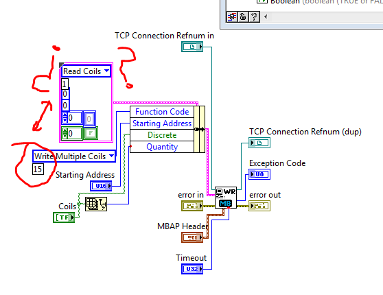
In this block diagram, 'Coils Read' and 'Write multiple coils' are enumerated values (or possibly ringtones of appeal, which is not serious for the purpose of this explanation). Enumerations assign names to numbers, to make them easier to read. The coils Read command is set to 1, the command to write multiple coils has a value of 15. You don't need to worry about this number, however, because the enumeration takes care of it for you.
The constant cluster containing coils of reading is there just to provide the correct data type (a cluster with the right items). Almost all the elements of the latter shall be replaced by the values of wired in the Bundle to node Name. For example, the value of reading coils is there as a placeholder for any function Code. the actual Code of the function is defined by plugging write multiple coils in Bundle by name.
Tags: NI Software
Similar Questions
-
Someone help me please understand what is this block? -Call Subvi
Hi all
During playback of a sample project a block stopped me. I could not understand what it is... once I click it (offline), it opens a Subvi, while runing the labview, it is clear that he will automatically call the Subvi. My Info is the one to call a Subvi VI main, you must use a static reference of Vi. Can someone help me understand what about this block?
I am attaching the picture of her and a container VI she also well... Simply open the block diagram of the file: "Caller.vi"... The Subvi associated with this block is fixed as well: "Config.."I would like to know what is this block name, how it is related to the Subvi and how the Labview call it automatically. .. I really appriciate any suggestions.
Thanks in advance
Concerning
-
What is the best way to keep the block diagram / cleaning of façade?
Hello
I'm relatively new to Labview so I'm not able to say if I'm overloading my programs or make my too crowded block diagram. I was wondering if there was some ways to tell if I can simplify my programming just by looking (perhaps only experience contributes to these things)?
I enclose my VI here. Currently, she is able to monitor the voltage and current of two engines. On the screen, you can see an indicator with the voltage and current values and there are cards that can display signals of different engines with a menu drop-down.
The façade is pretty clean, in my opinion of novice, but the block schema seems messy to me, just at the first glance. I foresee a problem occurring in the future however. In the future, I will have the VI to monitor 50 engines globally. All of the programming will be the same as the one I have now, but it will have 50 indicators and unfortunately 50 times just about everything. I would like to avoid this, but I don't know how I did.
I use a USB-6009. I use its four differential inputs to monitor the voltage and current of the two engines. In the future, I will get more units DAQ (25 in total because 2 motors can be monitored for each data acquisition). The new Renault will help will help with more resource space, but I think things complicate with the added option of 24 more Assistants of data acquisition (as used in my code).
Thanks for any help you might be able to provide!
Usually, it is above all the experience that will teach you the best methods for making your code to do pretty. I don't know anyone who is proud of his first application of claws. There are some resources out there to help with best practices, as that group on ni.com, but you will learn most of your own development.
Your façade is superb. FPs in general really are to you. You can do it as ugly or pretty as you want. When you have a few controls in duplicate and the Group of indicators, you should use clusters and berries to simplify. You can use a bit of cleanup in this regard, but not much. In addition, I personally hate read red text unless it is a warning any.
Your block diagram could use a little cleaning in a sense of modularity. You have a lot of repeated code, which you might consolidate in to a Subvi, which is used in multiple locations, or in a loop For. A general rule is to keep your block diagram within a single monitor. You should not scroll. Your application is quite simple, so it is difficult to BUMBLE

Here are a few details on your block diagram:
- Click with the right button on your devices on the block diagram and uncheck the "display as icon". You are welcome.
- Operations on each waveform "(x*2-4)" / 16 in double ": create a Subvi and/or run the waveforms through a loop."
- You do a lot of 2-element arrays and then indexing. Just replace the ones that have a Select node based on digital.
- All your code runs every time, including the knots of your property at the bottom, which is not necessary. As you learn LabVIEW architectures, you will learn how to get around this with the initialization and the output of code, but for now, you should put a case around those structure for only when the engine numbers change.
- I don't know how you're timing your main loop, but you should put a delay in there because you don't need the DAQmx node shoot as fast as your CPU will allow.
There are videos of intro free that you can watch to learn what OR think in terms of coding and teach you some of the basic features and such. Here's a three-hour course, and here's a six-hour course.
-
WHAT THIS MEANS WHEN IT SAYS VALIDATION STATUS: BLOCKED VLK?
Original title: NO VALID XP PRO
WHAT THIS MEANS WHEN IT SAYS VALIDATION STATUS: BLOCKED VLK?
Please make the answers in your original thread. You'll see a response from Noel about your problem...
Tricky
-
What is the unit of EXTENT_SIZE in v$ sort_usage, isn't this. blocks or bytes?
Hi all
What is the unit of EXTENT_SIZE in v$ sort_usage, isn't this. blocks or bytes? for 11.2.0.4
Thank you
You mean v$ sort_segment, no v$ sort_usage. The size of the measure is levied on one size of storage space, in the blocks.
-
Clean using SubVIs block diagram
Hi guys and welcome to my first post!
I m a bit new to labview, so be a little patient, if I do not understand everything immediately

Im working on an existing program that is used to control an MCU on BabyLin on my front, although I have a visualization to see live changes to the system. The program works very well so far, but I m trying to clean up the block diagram. This should be done by subvis, right? I ve read a lot about the size of the block diagram should not increase my screen. Well, im at a length of about 3 x 2 screens (24 "!) after trying to use subvis and to shorten the distances between structures. The only things remaining are huge amounts of local variables and references (they existed already before I got to know the program), mainly for viewing. If I create a Subvi part containing the people of the country, it will change the references that does not make the program more readable (and small), and I guess I can't put a new Subvi on references + Subvi.
You have any ideas what to do? I hope that I forgot something, otherwise, do not hesitate to ask.
Kind regards
Leo
Bob_Schor wrote:
To get a handle on the structure of your high-level code, write down (as if you were telling your boss or tell your wife - who knows, they might be the same person!) that you are trying to do. Keep it pretty General. You specified a number of steps? So maybe the top level should be a State Machine, or a message in queue manager. Describe you something that works at a constant speed, generating data that you have to manage "on the fly"? Maybe it's a design of producer/consumer.
You have a lot of initialization? Put in a Subvi, bring the 20 son out in a bundle (it's "Boss-word" for a Cluster). Your main program must have a few loops, with values that persist (possibly changing) during the program running in Shift Registers near the top of the loop, with tables and Clusters used to keep related items "consolidated".
Not too bothered by the size of your routine - I recently downloaded a monster 50-monitor the Forums (I did not even try to understand), up to 6 monitors is nothing!
Let "encapsulate the function" and "hide details" to be your guide in the reflection on the creation of the screws.
Bob Schor
To develop on the analogy of Bob, each talking point can be a Subvi. In other words, code group associate subVIs. The advantage of this is that it is much easier to solve problems because all errors will be localized to a Subvi. Errors no longer Chase around the block diagram. I guess you can use your current VI as an example of what NOT to do on the block diagram.

-
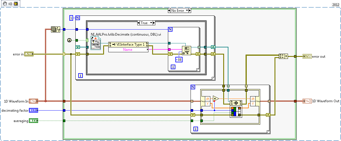
I have a double 2D chart I want to decimate continuously using the ".vi (continuous) Decimate" located in the range of Signal Processing. This VI is set on reentrant preallouee clone because it uses a FGV to save the State of the call to. What I could do, but do not want to, is having a huge index table and wire 20 + 1 table of DBL to 20 + unique VI instances decimate to ensure that each have their own data space and no 'cross-talk' doesn't happen, then 'picture of generation' all back after the fact.
I'm almost certain, there is a much cleaner way to do it with only one instance of unique block diagram of the VI decimate using techniques of the call by reference. I found my way to this link: Preallocated-Reentrant-VI-within-Parallelized-For-Loop that talks about something similar. After reading pages of four and the detailed help about the function 'Open VI référence' my head is spinning again on what option I want to spend (0x08 or 0x40 + 0x100) to ensure that whenever a slna 2D table come in, each of them is decimated by using the same clone that was used the last time it was called.
Although the DBL entry 2D array always has the same number of lines, now, it is not always in the future this number and ideal would not force me to create several references strictly typed in VI decimate that will have to change as grows the number of rows in the table 2D static DBL.
Anyone ready to set up an example VI that takes an array 2D arbitrary of DBL as input, decimating each line using the same clone independent of the "Decimate (continuous) .vi" and outputs the newly decimated 2D Array of LDM? Assume that each line uses the same factor of decimation and 'Sprawl' set to False.
Necessity is the mother of all invention and since it upsets me when I read a post that has a similar problem with no resolution, I felt compelled to post mine here. I'm sure it's better I can do within the current state of LabVIEW. The only question I have is what happens if I put the call by reference for loop be parallelizable? That trash completely the nature of 1 to 1 of what I intended?
-
Why the block diagram is disabled?
What do I do now? Please, look at the attached picture. A VI that I use as a Subvi in various different programs suddenly started looking like I had used the application builder to create an exe out of it (but I don't have!). The only options are Start and run continuously, and the block diagram is disabled. What I did to get into this mess? How to cancel everything that I did, so I can edit the schema-block again? For any help or suggestion would be greatly appreciated.
Thank you!
You have somehow managed to record without a block.
Go back to the last working back up and start from there. You have backups, right?
Lynn
-
Third-party tool to draw the rectangle on the block diagram
I know he was once a third party tool that allowed me to draw a rectangle of Nice double border on the block diagram. Yes, it's the not the front panel block diagram. It was very useful to make annotations and designating functional groups. Does anyone know what this could be? I installed Package VI Manager and went through everything I can think of without finding her.
Unfortunately, the documentation for those modules potentially very useful is poor. The 'Get info' is terse point of unnecessary and by clicking on "Product Home Page" rarely gets you more than a logo, not informative. Surely there should be more details somewhere.
I don't know what you're referring to the tool. What is this logo? Maybe someone can recognize.
What is the problem with the flat frame?
-
VI of script to read comments of block diagram
Hi people,
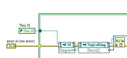
I have a small project to attempt to harvest comments in the block diagram, perhaps the help of scripts of VI. So, for example, when I'm checking #ToDo comments, I can get a list of the VI appearing in the #tag and collect the text. I think I found the method to get the comment, but I don't know how to recover the text in the comment. Here is a picture of how to get to observation in the block diagram (just using this as one small example VI)
Thanks for your help!
Rik
James.Morris wrote:
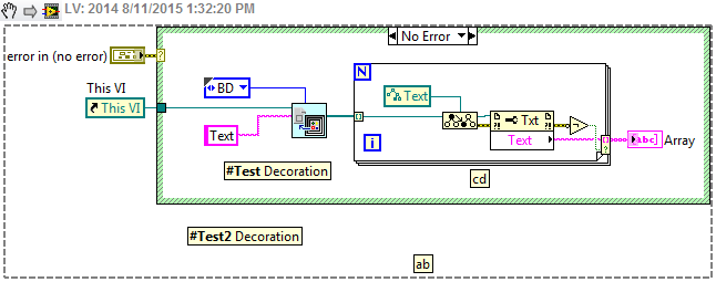
Here's what you want. It is worth noting that the current code only outputs the comment outside the structure of the case because you will need to dive into the structure for what anyone inside.
Yes this will cross all GObjects, but I'm sure there's a bookmark API Manager that will return comments bookmark if this is what you are looking for.
EDIT: Okay, there's an invoke node returns info bookmark on a VI but the VI reference may not be running.
-
a lot of Group of variables together on block diagram
I was wondering if anyone knew a good way to organize a ton of variables on the block diagram? For example, I have 32 switches in this program and whenever I need to read or write from them that I have to use half of my screen just to install in. I can't think of a way to make it work using bundles or subvis. I have attached a picture of how I do things now, but advice on you guys how it would be greatly appreciated! Thank you
Assuming that you do not use indicators and controls in the space of the façade, you can put a cluster around the controls on the Panel (would be helpful if you included a picture of the FP). That's what I did, but I still need more controls half a dozen in the same group.
Kind regards
Michael Tracy
Synergy microwave
-
Corrupt the VI block diagram (try to view the BD accidents LV)
The attached corrupt version 2010 VI in the room is '8810A control.vi.' I put work a few days into it, so it would be nice to get it back. I can open it fine to display the front panel. When you try to view the block diagram, an outline of the BD window appears and freezes LV. Usually, after a few moments, LabVIEW itself disappears completely. No error message; no sign of it in the taskbar or any where. I tried to save the VI to a previous version, but LV will receive an error. In trying to "Double hierarchy to the new location", I get a popup saying "LabVIEW: file generic i/o error.» I then did a copy of VI, open and tried to delete everything from the face before completely. Still can not go to the BD.
I think that what caused the error was when I accidentally clicked my mouse button that I arrived to move the cursor quickly through the BD of this VI. I couldn't tell if it hit or moved something on the comic. I don't remember for sure, but I think that at this time there LV froze and I had to kill him and restart. After happened yesterday, I moved on to work on other screws which have not been affected. I guess I'll have to recreate (because I had not yet created backups).
 in the future, I hope that I can remember save projects at least twice a day. I've used Mercurial and it works well. Hard lesson learned.
Try this. I saved to LV9, opened with LV9 then did a cleanup of comics.
-
Programaticaly inserting block block diagram.
Hello to all 2!
I wonder if there is a way to programaticaly insert a new block in an existing diagram.
Take a look at the attached vi to see what I mean.
So... When I click on an image of the corresponding function is inserted in the block diagram, having as inputs the two controls.
Is there a way to do this or is this just wishful thinking?
)Thank you very much!
It is possible to programatically manipulate the block scheme by obtaining a reference to it and operating on it with the use of the property and call the nodes. It's scripts of VI. You can write code that uses scripts in LabVIEW 7.1, but it can be imported in more recent versions of LabVIEW. This function is not supported by National Instruments. Being that it is not supported, I would not recommend research inside if you develop a code for a customer.
This should help you get started:
http://forums.lavag.org/VI-scripting-Readme-first-t1207.html
http://forums.lavag.org/LabVIEW-VI-scripting-F29.html&s=3fea8247be8d214406abf99a30e64e94 is a forum where you can ask on the scripts, being that it's about undocumented.
Welcome to the dark side, good luck in your journey and watch the rusty nails that you rummage through the attic of NOR. (lol sry, cheesy feeling on my lucnh break)
-
Recently a VI I have worked for a period of time started to run slowly. A large (5-7 seconds) delay occurs after I connect my hardware target before the VI continues processing. I'm trying to understand why, so I made a copy of my project and began to remove tabs with a lot of indicators in order to track down the precise cause.
That did not work, so I tried to pause execution during the delay of the program. I expected to see highlight in an active area code, but instead, it is showed in the figure:
The black outline flashes during execution paused. Once separated I did, there was much smaller black box in the lower right corner... in other words, between the 2 times, it is as if it is highlighted on a loop with a stop command in the lower right corner.
Also note that the horizontial and vertical scroll bars are completely to their extreme. It is an area of the block diagram that I do not at all. In other words, if I scroll manually on this same area of the code, there is nothing there. In other other words, it of like exeuction program is stop and highlighted to a region of code that is not yet visible.
I know it is possible to hide the objects in the front, but is it possible that there is a code of block diagram which is hidden? What can I do to understand what it is that is highlighted as shown above, when I hit the break?
Thanks in advance.
You can do a cleaning of block diagram (but not record) to see ifanything was hidden. I would do that, especially if I inherited code. I saw subVIs hidden behind the case structures and other things like that.
-
Block diagram of... block diagram
Hi, I need your help. IM the wrong person for this post, but I have to do, so I depend on your help. I need to explain how LabView (pasted below) program works, but I don't understand it myself
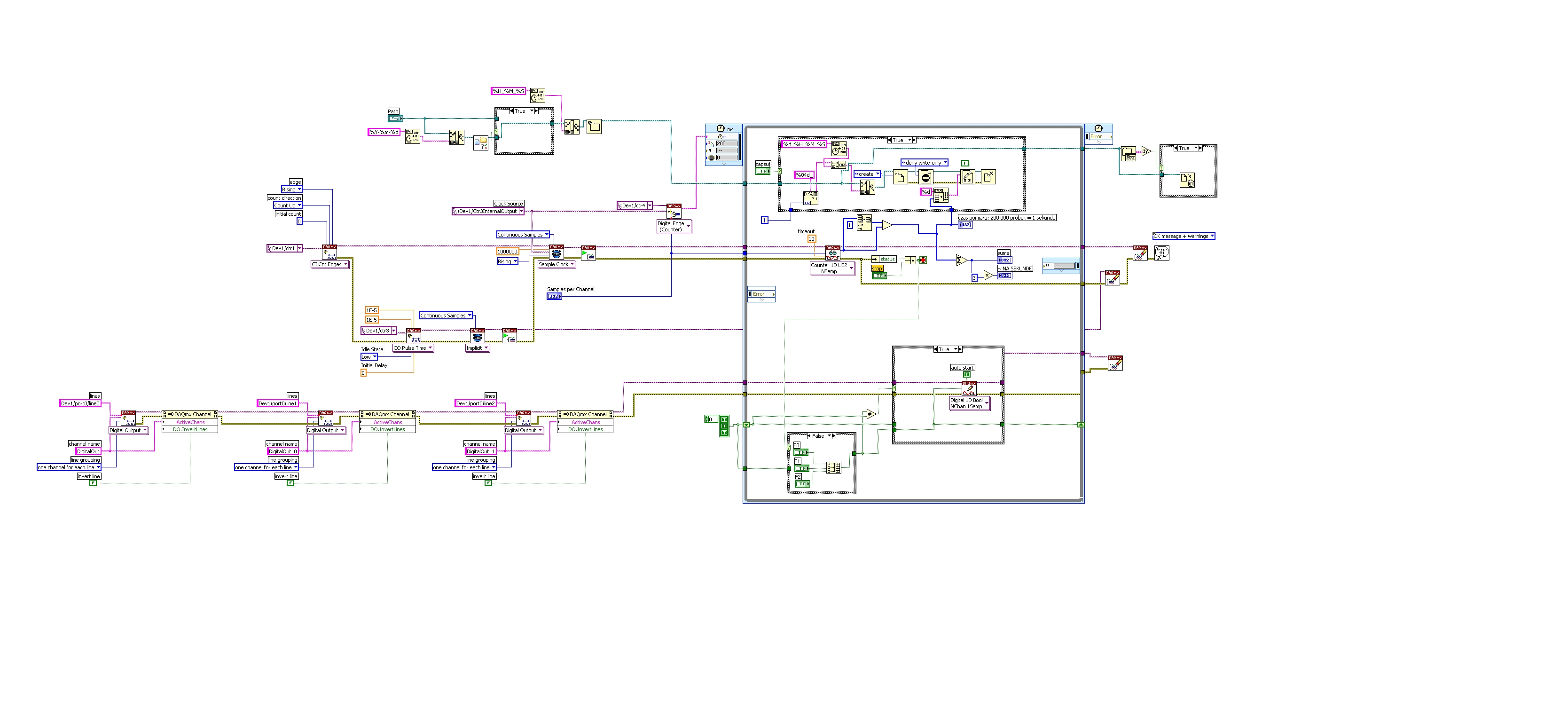
I would like to ask if someone can create a simplified block diagram of the pattern-block LV I paste it here. I appreciate all the help and please take considaration I am short on timehttps://DL.dropbox.com/s/yd10z7yorxvbzux/LVdiagram.jpg
It is a counter. Meter of photons to be exact.
Hi, Rodolphe,.
I will try to explain briefly what is this application:
Following materials may help you understand the underlying concepts:
http://www.NI.com/PDF/manuals/371022k.PDF
It is the manual of series M - chapters 6.7 and 8 explains how digital lines, meter and what is a PFI.
When you open the block diagram of your application, you can see several branches ranging from left to write.
The first one on the top is to create a path to a file. This path will be used to write data to a binary file. The data represent the number of impulses which can be counted as edges rising a signal connected to the meter to 1. This information CA be read if you follow the logic on the second branch from left to right, where the first VI is CI INT edges (edges of counter), and it will count up, on a rising edge of the signal connected to CTR1.
Later, there is another task created for counter 3, that generates impulses. The pulse seems to have 10uS length and 50% duty cycle. The signal generated by this counter is used as sample clock for measure and 1 meter. In addition, the same meter signal 3 will be used by 4 meter from the digital dashboard and create a clock which will clock the timed loop. Basically, the frequency of the timed loop is given by the task on 4 meter which counts pulses generated with meter 3.
The 3rd branch from left to right, creates three tasks on three outputs digital: Line 0, 1 and 2 where it is controlled by three buttons F0, F1 and F2. Basically, your timed loop will be a specific iteration, and every iteration buttons will be read and will be updated to the specified digital output above.
Whenver there is a mistake or the button is pressed, your application stops and closes the binary file and dealocate resources used.
I invite you to also look in the above manual.
Best regards
Ion R.
Maybe you are looking for
-
Equium A60-181: Win XP does not start successfully - the BSOD reboot
Hello. I have an Equium A60-181 which has an operating system problem.Loads of XP logo at the beginning, when it happens to show the log on screen, it is a quick blue screen of death error, and it restarts. I tried to go into safe mode, but it blocks
-
I bought this laptop IBM thinkpad at an auction. He says that I have a counterfeit Windows xp copy, it's on this computer, when I bought it. I can't afford to buy a new copy of windows xp, I've heard that if I told where it came from or who made it,
-
When I try to run this application, all that I get, it's a message that says "unable to download Internet convenience stores-check" can someone tell me what to do next?
-
His intermittent external speakers
Vista & Dell laptop: intermittently, no sound on external speakers. correct internal speakers. After some time, reboot bugs, but not all the time. Frustrating, this problem occurs after disconnecting from my laptop and use it is not connected to exte
-
Problems connecting to the Internet, and can not use the command prompts
Hi I started having problems with my internet via wi - fi access, but all my other devices and other portable computers have no problem accessing it. I used videos online and other forums to try to solve this problem. I tried to use the "netsh winsoc