Straing gauges - calibration for measurements
Hello
At first, I'm sorry for my English, I'm Polish and I do what I can
I t prepare strain measure simple application on cylindrical tube. Has created this task to MAX and now I have a problem during calibration. Performed shunt calibration.
The main idea of my program:
After clicking on "run" arrow in the upper-left, I will send to the tab named "calibration"(default tab) (it can also be cluster tab instead, is not serious). "." Then I load sample tested with, for ex. 1000N and the program of calculate the coefficient between the force (1000N) and the real value of NOR-9237 (configured as analog input - bridge to the MAX). Then I move to the next tab, described as '' measure '' when I perform a simple measurement with strain vs.time graph.
I have established that the dependence is linear, so I have to use y = ax + b formula. Assuming that 'b' 0, I have to find 'a' - how can I calculate and how can I keep it for use in the next tab, 'measure '? I have no idea...
I attach no examples of my program, because there is nothing difficult yet - DAQ Assistant and graphic waveform...
DAQmx provides a way to create "Ladders", but also "Tasks" a linear scale is easy to assign to a channel in a task.
I'm in the middle of an upgrade from LabVIEW today so, Kudos to anyone who publishes the screenshots I can't get right now.
Tags: NI Software
Similar Questions
-
The compass is out of 90 degrees. Is there a software patch or calibration for this?
The compass is out of 90 degrees. Is there a software patch or calibration for this?
See section reset or disable location Services of privacy and location in 8 and later - Apple iOS Support Services. Back to zero must recalibrate the compass.
TT2
-
Do I need a sheet of calibration for CM719A - HP Designjet T1120 SD-MFP printer range? If Yes, where can I get it?
Looks like this would be a necessary element for accuracy of current scan. But I'm not 100% sure for this scanner.
Thank you.
The item is expensive.
http://www.sparepartswarehouse.com/HP, Printer, share, Q127760030.aspx
-
What are the best settings to standard calibration for the XBR65X850C?
What are the best settings to standard calibration for the XBR65X850C?
Hi DRATCLIFFE,
Thank you for your time to write a post.
We are very sorry for the late reply.
Change the picture or the sound settings of your TV depends on your preferences and on what you watch/listen to.
You can use the settings preset for image and sound.
In addition, to better enjoy your viewing experience, follow these steps:
- Install the latest software update. The updated software and the driver for your Sony product are available online.
- Set the automatic software download setting to automatically download software updates.
Thank you
^ RonIf my post answered your question, please mark it as "accept as a Solution.
-
cartridge not calibrated for better print quality hp5510 photosmart
Cartridge not calibrated for the best print quality, Photosmart HP5510. Again black but very little about the colors, jump a few lines, monochrome printing. Tried to realign, cleaning of printheads etc..
Hi, if your problem is of poor print quality then its majority as ly the cause is very low levels in your color cartridges. Here is a link to a support document which takes you through a few steps of troubleshooting, but you should probably have cartridges on hand before you start, because it is one of the first suggestions, you will receive.
http://support.HP.com/us-en/document/c02914910
Best.
-
Configuration NI9219 for measurement of deformation
Hello!
I am putting in place a strain measurement VI using Labview. I use the NI 9219 module on the chassis NOR cDAQ 9172. My extensometer is configured in a quarter-bridge arrangement and I did strain gage connection accordingly (to the terminals 3 & 5 in NI 9219). However, I do not understand what are the terminals of TEDS and what to connect to these terminals. Can I use virtual TEDS for this? I couldn't find a virtual TEDS for NI 9219. Any information to resolve this issue would be much appreciated.
Best,
Nyquist99
Hi, the terminals of TEDS are only for transducers, as a strain gauge, that support the TEDS (Transducer Electronic Data Sheet). The standard of TEDS is just the ability to a transducer to record information about itself in the internal memory. This information includes things like dates and calibration constants, one of the factors, electrical characteristics, etc. It is stored in a standard model which can be read by computers and the DAQ cards via these lines TEDS. For your application, you must just let unwired and to the top of your strain of installation normally gauge.
-
Using the SCXI-1520 module for measurement of torque
Hello
I'm working on a project that requires a measument couple in real time on a speed-shaft drivetrain configuration phase.
I have the SCXI-1520 module, and I think with a with a configuration of full-bridge strain gauge to do this.
The problem is that it is not possible to connect to a real-time measurement, so my first solution was using some sort of wireless transmission to receive data in the SCXI-1520 module
The Arduino + Xbee seems to be the best way to go, but at the same time, I think I might have a few problems of conditioning of the signal while transmitting data to LabVIEW through the SCXI-1520.
Don't you think it's the best way to do it, or is there a better solution?
Thank you!
Hi Kenny,
What type of operating system are you using? When you say 'Real time', do you mean look at a signal when it occurs? If you use communication networks, you will not be able to get truly control in real-time because communication networks is not deterministic, and you cannot guarantee the synchronization.
If you try to get a signal and he discovers that you buy it, you should be able to use the Arduino and LIFA with LabVIEW. Adding the SCXI-1520 will not add any additional resolution in this circumstance.
Best regards
Anna L
-
Can I use a NOR-9244 for measuring single-phase AC 2-wire 480V?
As the 9244 module is rated for a maximum of 400 v L - N and L - L 800V, to measure 480V, I would need to connect to AI0 AI1 and let the neutral entry floating. Manual outlines all single phase measures referred to the input neutral and has some instructions on the conversion of L - N L - L measures, but it is expressed not bad so I don't know if it tells me that I can directly measure the voltage through AI0 AI1, or not.
Can anyone confirm that I can make measurements with 9244 cable in this configuration, until I drop the $$$ to buy it?
Hello MStewart,
A distinction must be made between Vpk and Vrms.
@GerdW is correct that the input device is ~ 1000Vpk (997.5Vpk). However, this translates into ~352.6 Vrms
The side of 800 Vrms for line (L - L) measures is for multiphase applications.
As you take a single-phase measure, you would use an AIx-neutral (L - N) connection.
The diagram for this is detailed in figure 12 on page 25 of the Manual:
<>http://www.NI.com/PDF/manuals/376131b.PDF >
So to measure above 400Vrms on this unit, you will need to use a power supply external to resign from the tension, as mentioned in the white paper in (specifically the section of voltage):
<>http://www.NI.com/white-paper/8198/en/ >
In summary the 9244 cannot directly measure 480Vrms. You can set before the signal to less than or equal to 400Vrms
I hope this helps to clarify your question!
See you soon,.
-ChristophersonJ
-
Can I have a global calibration for different images sizes in VBAI
I run a VBAI algorithm on images from several cameras to linear scan. We use a square, simple, calibration (.42mm/pixel) for each image, they are always 1024 pixels wide, but can vary in length of the image. Currently, I use several instances of Calibration Wizard then 10 to account for variations in length, but it seems to me that the internal calibration resulting is the same for each instance. So is it possible that I can set up a unique calibration use if for any length of the image?
Thank you
This is a feature that we added in the latest version of Vision Builder AI (2012), which will be available very soon.
Would it be possible for you to use the LabVIEW execution step to calibrate your image? If so, you can call a LabVIEW VI that sets the calibration using IMAQ Calibration2 Simple to set, after the steps in the acquisition. Once the image is calibrated, all subsequent steps must return results calibrated, even if you do not use the VBAI built in calibration.
Christophe
-
Generation of weather in TDMS for measures of multi channels channel
Hello world
I have to write an application with five measures will at the same time... then it must be saved in TDMS each channel being its own channel of time just after she... IE sequence of the canal as below
Channel group
Measurement1
(EDT) 1
GCA2
TIME2
Measurement3
Time3
Measurement4
Years.4
Approvisionnement5
Neuve5
Each time channel should have "dt" for its number of measure...
So far, I m succesfull in the measuring channel recording only all the... But I have no idea how design for each measurement time line...
I tried to get the time I receive the data using functions as below
GetSystemDate (month & day, &year);)
GetSystemTime (& hours, minutes & seconds);
sprintf (timeStr, ' %d/%d/%d % 02d: % 02d: % 02d ", day, month, year)
hours, minutes, seconds);This will generate the channels of chain of time... but my requirement is of data type ' Date/Time' used on larger scale of the axis in tiara...
Any help
Thank you
HS
HS,
There are two ways to store calendar for a channel information in a PDM file.
You can only use the first method if timing information is regular (spaced), which means that it can be described with the only values t0 and dt. This method translates a single channel in tiara which contains data values and stores the calendar as properties on the channel information. Note that in this case DIAdem will treat time as relative values with no basis of absolute time values. The properties you must set on the channel are:
(1) wf_start_offset (mandatory), the type is TDMS_Double, contains the time value t0 of the first data point of some units that you use and can just be 0 if your t0 value has no meaning other than as a reference for all other values of time in this channel point
(2) wf_increment (required), type is TDMS_Double, contains the dt in whatever units you use
(3) wf_samples (mandatory), the type is TDMS_Int32, contains the number of samples in the waveform
(4) wf_xname (Optional), type is TDMS_String, contains the name associated with the x-axis of time and will be used by the tiara to label the x-axis in tracing this waveform
(5) wf_xunit_string (optional), type is TDMS_String, contains a string that describes the x-axis of time units and will be used by the tiara to label the x-axis when tracing of this waveform
You can set the properties above using the TDMS_SetChannelProperty function.
You can use the second method for regular or irregular (not also spaced) timing information. This method translates a channel with your data values and a separate second channel which contains the absolute timestamp values. From your original post, more like what you want. In addition to your data channel, you must create a channel of timestamp. Call TDMS_AddChannel with a data type of TDMS_Timestamp to create your channel of timestamp. Call TDMS_AppendDataValues with the values of type CVIAbsoluteTime to write the Timestamp values in this channel. You can create individual type timestamp values CVIAbsoluteTime by calling the functions of absolute time in the ICB Utility Library, such as GetCurrentCVIAbsoluteTime and CVIAbsoluteTimeFromLocalCalendar.
I hope this helps.
-Jeff
NEITHER
-
6225 DAQmx names for measurements of the differential pair
All,
I came across this post trying to find out if there was documentation to show who's analog inputs are coupled together and what name DAQmx controls call these pairs.
Messages from the author a drawing which I think is correct, but it is not an official document of OR. I'm looking for documents that says exactly what the name is for each pair during their use in a command DAQmx. I know literature 6225 AI0 and AI8 form a pair, and AI1 and AI9 are a pair, etc. etc. What I was trying to find, is documentation that shows that the name of each of these pairs, what I should do in the DAQmx calls during a differential measure. Currently, I am assuming that the AI0/AI8 pair is referred to as AI0 when the measure differential. I have just followed the list of pairs in the manual of the user from left to right and from top to bottom and naming of AI0 to AI39. I really was hoping that there was an official document that says what were the names of each differential pair.
Can you point me to the appropriate document or tell me that it is not an and that my assumptions are correct?
Thank you!
Doug
Doug,
There is not an official document similar to the one in the related post that shows the AI0 + and AI0-. The differential channel will always be referred to by the positive terminal. It doesn't matter what differential channel number it is. For example, the Channel 9 differential uses AI16 as the positive terminal. All configurations in DAQmx must be configured using AI16 in differential mode. The drawing was published is not official, but it is correct.
Kind regards
Danny F
-
How to use an internal counter of the cDAQ-9172 for measure PWM and generate the frequency?
Hello
Requirement of my project is to measure 6-channel PWM and generate 5 frequency channels.
Suggestion of engineer OR bought cDAQ-9172 chassis and NI 9423 (8 DI correlated) and NI 9474 (8 correlated DO) for this requirement. I have a few questions
Article:
1 > what should I know to customize my CompactDaq 9172 chassis
http://zone.NI.com/DevZone/CDA/tut/p/ID/9367
I know that this way to synchronize the physical support 32 correlation system pin o for housing 1-4.
=> I'm not really sure how to use these channels synchronization support.
2 > using internal counters on one NOR cDAQ-9172 as a sample for other tasks clock
http://digital.NI.com/public.nsf/allkb/ADFC4DD8C9690232862575B70079FBD4
I know that I can change the ownership of the physical channel so I can get 2 meter outside the frame 6 and 7.
=> I do not think that this solution will be me because I can use only 2 counters with this method.
Could someone tell me please how to fix my project requirement? How to choose the setting for DAQmx screws?
I have experience with measure the PWM and generate the frequency, but with separated against only.
Best regards
Thang Nguyen
Hey Thang.
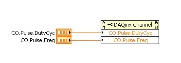
AHA... for this, you can use the channel property node.
See you soon
Lab
-
You can create a test of calibration for speech recognition?
Hello
I'm in love with the character animation! Thanks to the development of the latter.
I would like to make a suggestion for a feature - add some sort of calibration tool for the part of speech recognition, so talk to a range of phonetics and it maps the lip sync more accurately.
Is this something that can be done?
Also, I have a beard, and he keeps making my character smile while my mouth is not open. No work around for this (other than a shave?)
I have drawn, established, registered and made a lego man talk for 10 seconds in less than two hours this morning. If your development team wants a copy of my revision project files let me know, I am happy to share these for R & D purposes.
Keep up your excellent work!
see you soon,
Brendan Cox
Hi Brendan... Thanks for the request. I connected it to our internal database.
For the issue of the beard... Could you try to adjust the light on your face? Does that help?
We'd love to see any work you have done. Feel free to me message directly with a Dropbox or similar link. Thank you!
-
What is 'caméra Calibration' for?
What is 'caméra Calibration' in Camera Raw? It is to make adjustments to digital cameras to make more accurate colors in Camera Raw? Or just to refine RAW images?
the main role of the sliders is to fix incorrect camera profiles. It can also be used for image editing, but it's easier done section STL/levels of gray
-
Must install Labview App on cFP2200 with feature plug & play for measurement modules
Hello
I am trying to install a monitoring software on cFP2200 devices. This software uses anywhere from 1 to 8 modules of I-102. I want to be able to deploy my build to the fieldpoint without having to know in advance how many modules will be there.
My plan to achieve this was to design my application to assume that all modules HAVE 102 were available to read to go, throw an error that I catch and delete if they weren't. It works perfectly in tests of interpreted code. I managed to disconnect the field point, 102 HAVE devices to different locations than before, and my software could find them and ignore the slots where were connected HAVE 102 s.
A question is asked now when I try to deploy a compiled version of this app on the fieldpoint. When I do that, I get a "conflict resolution" popup that lists all of the I-102 s who are not connected at deployment time. I have to choose 'cancel the deployment' or 'Skip deployment' in these cases. So I am unable to find I-102 modules if I move them to one location other than when they were connected to install or put new ones in.
We will put these modules at customer sites and we want the ability to develop so that it contains some 102 HAVE more or less as the customer systems expand and contract. Under the current situation, I have to re - install the software manually whenever they move a module that is not really an acceptable long term solution.
Are there ideas about how to address the issue?
Thank you
Kelsey Golden
I just realized that the "conflict resolution" window really means nothing. As long as I select 'Skip', I can always move the modules or new install! It makes me wonder what the conflict resolution is intended in the first place if he is not actually stop me using the modules later.
For all those who want plug-and-play in the future, my solution essentially try to read all possible addresses and ignore those throwing errors basically seems to be the way to do this. Just ignore the stupid conflict resolution window. I of course hope that the fact that I can still install modules in locations where conflicts implicitly he wasn't their installation is not a defect that NEITHER patch later outside.
Maybe you are looking for
-
Subvi in the memory of the loop
Hello I have a loop that contains 3 subVIs that are exactly the same (that's why I use a Subvi ) each Subvi controls a device (again 3 devices that are the same). The entries to each Subvi is from a Mathscript node. Thus, on each iteration of the loo
-
I'm playing the game "Railroad Tycoon 2-Gold edition" on my laptop which is running Windows 7. Whenever I try to install it, he repeats to me - "the program or feature? \G:\_setup\setup.exe cannot start or run due to incompatibility with 64-bit Windo
-
Failed to retrieve. Files - error indicating 0 * 80004005 zip
Original title: Search search index indexing re-indexing re-index research research research service troubleshooting troubleshooting I can't extract the zip file. error 0 * 80004005
-
I was just curious as to what that the thoughts of people on all these registry fix programs and other programs guaranteed to speed up your computer. R they useful? Do they work? Or R they the worst 2 2 your PC?
-
Import and editing a DVD into Windows Movie Maker
Hello I have home video on a DVD. The DVD is a file 'Video_TS. I can't import into WMM to change. I have to convert the VIDEO_TS file in a different format to import it? Thank you