Synthesis of filter multiband in LabVIEW
Hello
Y at - there some facility in LabVIEW that allows to synthesize the multiband filter, or to use another tool like Matlab.
Thanks in advance
Paavel.
What of it:
Parks-McClellan VI - 2012 aid LabVIEW - National Instruments
http://zone.NI.com/reference/en-XX/help/371361J-01/lvanls/parks_mcclellan/
In addition, if you have enough resources and if your program is not the critical, you could simply put a few filters in series.
You program the FPGA? What you want to do at all?
Greetings
Brandizzl
Tags: NI Software
Similar Questions
-
If the butterworth filter available in LabVIEW FPGA is cascade, can I get a higher order filter?
I need a 10th order filter lowpass butterworth with cut-off frequency 5 kHz. Can I build by 4th cascading of 2 order butterworth filters and 1 2nd order available in LabVIEW FPGA each filter in butterworth with cut-off frequency 5 kHz?
This will increase the amount that your data will be filtered but will not increase the order in the Manor that you think. If you cascade two 2 4th order filters and compare that results to a filter of order 8, the resulting field filter cascading bode would look more like a 6,5e order filter.
Logan H
-
Hey guys,.
I the DFD Toolbox and already built a few low pass FIR filter. I have a sampling rate of 50 kHz and I decimate it with a CIC filter with rate variable decimation. After the CIC filter, I need a high-grab for the low-pass filter FIR because I do want my DC signal. As I can change my rate of decimation, my FIR filter sampling rate changes also.
The problem is that the coefficients of the filter cannot be changed during execution as the Butterworth IIR-filter function, including labview has implemented in the mathematics of the fpga function palette section.
Are there examples how to build FIR filters where I can change the coefficients on the run?
Think you can build a low pass FIR with the DFD toolkit and simply change the table with the coef. for a control? I could change them on the track...
Greetz
Slev1n
Hi Slev1n,
just found it in the community, maybe this might help you already:
Polyphase Interpolation FIR Filter on FPGA with Diabaté and Coregen
https://decibel.NI.com/content/docs/doc-16650
Greetings
Michael
-
application 2D median filter for images
I want to use the function of median filter 1 d LabVIEW for application table 2d (image). Vision doesn't have this feature (or I can't find not [using Vision 8.5]). I guess I can apply the median filter 1 d through the lines, then transpose the table and apply again to the lines (really columns but now the lines because of the conversion). Just like the use of the 1-d FFT for 2d FFT. Is this strategy the correct?
Thank you
Don
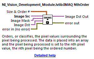
That's where - IMAQ NthOrder under treatment: Image filters.
By default, it takes the middle number of a 3 x 3 around each pixel region, but can be set to be the biggest, smallest, or any place in between. Also the ability to set the size of the filter, although it is a non-linear filter (so why it is not separable as you suggest) the time increases significantly.
-
Hi all
I allowed for students to install the version of LABVIEW. I'm new to the LabVIEW.
I installed license Toolkit LabVIEW Digital Filter Design in my laptop. But I can't find the options of digital filter in treatment of the signal from the controls palette. Its not there despite the installation. I checked in the license OR Manager he said toolkit Digital filter design has been enabled for this computer.
Can someone please help locate specific digital filter of this Toolbox options? How can I check the functions in the range control to the Toolbox, I installed?Thank you
IHAVE license fot the following content:
LabVIEW Student development environment
LabVIEW Toolkit for LEGO MINDSTORMS NXT
(Installed) LabVIEW Control Design and Simulation Module
LabVIEW MathScript RT module
LabVIEW System Identification Toolkit
Toolkit LabVIEW Digital Filter Design (installed)
LabVIEW Modulation Toolkit
LabVIEW SignalExpress
Module OR Vision Development
NEITHER Vision Acquisition Software
OR DIAdem Student Edition (installed)
(Installed) NI LabVIEW Real-time module
OR LabVIEW FPGA Module (installed)
LabVIEW database and control Module
LabVIEW Mobile module
LabVIEW PID and Fuzzy Logic Toolkit
LabVIEW Robotics module
LabvIEW Simulation Interface Toolkit
LabVIEW SoftMotion
LabVIEW Statechart Module
Motion Control and Motion AssistantHello
LabVIEW 2014 32-bit, he will find-> design of digital filters signal processing.
In Labview 2014 64-bit, I can find it or the other. I know that some tools are not supported in LV 64-bit. I couldn't find documentation on the system requirements for this toolkit so I could not say it, maybe you can change at LV 32 bits?
Good luck
Danielle
-
Compressor export crash Multiband + Audio Crossfade (constant power)
It took me 6 hours to locate the last night so I hope someone gets use out of this. The main elements causing the crash are certainly the Multiband Compressor filter and melted transition chained constant power, but the underlying issue can replicate under other combinations, then here's all that:
Platform: MacBook Pro (retina, mid-2012), 2.3 GHz Intel Core i7, 8 GB 1600 MHz DDR3, NVIDIA GeForce GT 650 M 1024Mo, OSX 10.11.5 (El Capitan)
The sequence settings:

Audio file of source Zoom Handy Recorder H6:
Type: Windows audio WAVE file
File size: 1.17 GB
Audio Format: 96000 Hz - 24-bit - Mono
Project Audio Format: 96000 Hz - 32 bit floating point - Mono
Total time: 01:12:25:06400
Multiband compressor settings: broadcasting,-3 db margin (limiter), output of 7 db gain (any other default =)
Melted transition chained audio settings: default (any length will cause the crash)
There is also a Denoise filter (-10 db) this but in my tests, this isn't a factor, any being deleted or changed the crash will be only or even occur when the filter Multiband Compressor and the crossfades are both present. If you plan to export directly from first step "Rendering Audio Files" will begin then stop early and skip the step where it freezes at 0% (must forcing app resignation). If you queue to Media Encoder will begin step "Audio Préparation" then stop after a few and its status as it is 'impossible' with the following error:

Was of codec H.264 - Match Source - broadband, but it will crash with any because the cause is rendered.
My solution for now is to finish edit, export audio only with all the filters I need EXCEPT Multiband Compressor, then import and apply Multiband Compressor before exporting the finished video.
Hope that helps, please correct.
DAT 96000 Hz audio... No help, not just that I've never worked with everything above 48000 Hz.
-
Hello everyone,
I use a NI 9361 module to measure the speed of rotation of a shaft that rotates through an electric motor.
I am faced with loud noises because of this electric motor; When I run it, my meter directly measure frequencies up to 1 MHz, even when my tree is not running. I can't see the same phenomena when I'm looking at the edge of counting results...
I tried to use the pulse width filter inside my Labview application to filter the signal but I couldn't find anything sufficient.
Anyone who has ever faced with this kind of question, and if so, is there a solution to cope?
I thank of altogether.
You use a shielded sensor connection? You can also try to raise the level of signal on the 9361 threshold if you CSR.
-
I want to "stack" a DSP filter on a LabVIEW waveform. 'Stack', I mean just run twice, but with different cut-off frequencies of; I'm trying to simulate the actual hardware.
I use a basic built-in LabVIEW DSP filter: \vi.lib\Analysis\3filter.llb\Butterworth Filter.vi
It's very simple, if I run on a waveform, produce an intermediate signal, change the cut-off frequencies of, then run it again on this intermediate waveform.
But here's where things get difficult. I want to run it live, or on a point by point basis...
As the Butterworth filter is re-entering, it has a ' init/cont' entrance which makes it quite easy to run if I do not put the filter; I just set the ' init/cont' VI entry to false on my first point, true on the following points, and my resulting waveform is the same, as if I ran it all waveform. But since I'm if based on the internal state of the VI reentrant, I can't really run it put on the script point by point, because the internal State could get confused by what cut-off frequencies of game I use.
My best solution for point by point analysis is to make a copy of the Butterworth filter and for each point, use the filter Butterworth of LabVIEW of origin with one set of cutoff frequencies, then the copy of the Butterworth filter for the second series of cut-off frequencies of. While this works, it seems wrong to make a copy of a built-in function to LabVIEW. If I update LabVIEW, so I would use two versions of the Butterworth filter.
Is there a better way to do it?
Hello bmihura,
I'm a bit confused on what you're trying to accomplish. Would it not possible to join code examples of the scenarios you describe so that the community is better able to help you?
What do you mean by "it seems wrong to make a copy of a built-in LabVIEW.". If I update LabVIEW, so I would use two versions of the Butterworth filter. »
Is "Filter of Butterworth origin of LabVIEW" than that found in the vi.lib that you referenced? Are there two different Butterworth filter screw, you ask the subject?
This sounds like something you might be able to use a loop For, but it is difficult to say without seeing your code.
Thank you
Joel C.
National Instruments
-
filtering data for temperature measurement
Hi, need some help here.
Before I add in the filter, I get the graph like figure 'graph-1. PNG ". But it is false because impossible, temperatures can drop to 30 0 30 0 31 0...
After I add in the filter (as shown in the "filter graph n. PNG"), the chart is to look like figure 'graph-filter. PNG'. The graph move continuously in but the scale of the x-axis is changed.
So, how can I solve this problem in order to get the graph constantly move (will not fall back to zero) and the x-axis of the correct scale (for example, 0 to 50 degrees Celsius). What kind of filter should I use.
emergency aid!
THX.
Cournoyer,
To my knowledge no instrument will not give this temperature difference, I would like to know how you measure the temperature before you apply the filter check your labview code if your postal code here, I can help you more.
Siva.
-
Coefficients of FIR (Hamming window)
Dear Sir/Madam,
I'm evaluating a simple convolution filter (low pass filter), to produce the coefficients to be used for the signal FIR filtering on the ARM microcontroller.
I used two different softwares to design an appropriate filter:
1 Labview (digital filter design)
2 Matlab (Signal Processing Toolbox)
I'm confused, because the coefficients of the result are not the same (the image attached below). (100% sure) Matlab and Labview (not 100% sure) use nomalized frequency as input for the design. The normalized frequency is:
FN = fcutoff / fsampling;
I tested in Labview on some signals with different fcutoff and fsampling, BUT with the same normalized frequency and the result was always the same (so I guess that Labview uses the normalized frequency also).
The filter settings:
FN = 0.2
type = low pass
= Hamming window
filter order = 24
ntaps/coefficients = 25 (filter order + 1)
The result:
It seems that the filters are not of the same order - the width of the main lobe is lower in the Labview example, and the height of the lateral lobe is larger. To my knowledge this suggest that the order of the filter is greater than one in Matlab. But both filters produce the same number of coefficients...
LabVIEW 'code' (only the coefficients of the numerator, since it is not a recursive filter):
and the code corresponding MATLAB:
coeffML = fir1 (24,0.2);
Anyone know the reason for this? Or I'm just a stupid mistake?
Thank you and best regards,
K
Greetings Alain,
I had a look at your problem and found a short explanation. The difference is how can you understand the frequency standard and how Matlab.
You can normalize the frequency by fs or frequency of nyquist (fs/2 as Matlab does). That is why your result for LV is different because you
expext standardization by fs.
Details can be found here:
http://www.MathWorks.com/help/signal/ref/fir1.html
"Wn is a number between 0 and 1, where 1 corresponds to the Nyquist frequency.
http://en.Wikipedia.org/wiki/Normalized_frequency _ (digital_signal_processing)
"Some programs (such as MATLAB) that the design of filters with coefficients of real value using the Nyquist frequency (
 )" as the normalization constant".
To solve your problem, whenever you want to compare results Matlab of the coefficients of FIR with LV filters, you must multiply the fs in BT by 2 before standardization.
I have also attached example program with comparison where the default values are calculated according to the above recommendation.
Have a nice weekend.
-
filtering of noise over 200 kHz
Hello!
I'm recording ultrasonic vocalizations of rat at 1 ms/s using an acquisition of data PCI-6132. One of my colleagues is ultrasound analysis of data from the records and asked me to apply a filter on the signal, as it is registered. He asked the specifications was to "filter noise on 200kHs, with a steep slope. I have no training in hearing analysis, so I have no idea what he's talking about, or how to impliment it. Can anyone interpret this and help me understand this? Thank you!
Matt
When I had to filter signals in LabVIEW, I had success with the express VI, called "filter". You can find it in the following range: "treatment-> conditioning of waveform of the Signal-> Filter.VI.
Before we begin, I noticed that your condition is to filter "noise more of 200 kHz. This means filter any more than 200 kHz or just 'noise '?
If you filter any more than 200 kHz, there are several parameters that you need to pay to reach your goal. Double-click the Filter.VI once you have he fell on the block diagram. The first thing you need to set is the same type. If you want to filter all above 200 kHz and spend everything below 200 kHz, you want a low-pass filter.
Since this is a low-pass filter, you will have only a cut-off frequency. It's 200 kHz is your case, since you want to spend everything below 200 kHz.
For a slope steep, I like to use the elliptical topology. You can start with an order of 3 to see if it produces the answer you need.
I would recommend search filters on a site like Wikipedia, if this does not produce the results you need. Using this VI will take you where you need to go, but you may need to adjust the settings based on your signal. However, I think this will at least get you started in the right direction!
-
How about using labview vi of the filter and multiply vi to replace the analog filter and amplifier
Hi all
I use a data acquisition system to acquire a weak signal, it seems to a voltage amplifier and low-pass filter before the acquisition of data. I was wondering, if I use low-pass of the labview vi of the filter and multiply vi to process the signal picked up by DAQ, can I get the same effect as the analog low-pass filter and amp?
Thank you!
No!
1. any system of sampled data must be band including prior to sampling in order to avoid aliasing. It is impossible to remove aliasing after collection.
2. the resolution of the DAQ system will be so low that you'll very 'fat' scanning and you will lose a large part of the information in your signal.
Sorry, but you need to amplify and filter in the material before the data acquisition device for best results.
Lynn
-
How to create a filter by using the function of transfer mathscript in labview
Hi all
I am currently designing a filter in labview using a Mathscript loop. The filter can be represented in the transfer function. I have attached the equation of transfer as well as its value function and the desire of graphic amplitude vs. frequency should I got to it. Also, here is the transfer function written in Matlab.
B1 = tf ([57.5221845], [1 51,017077 205.1868]);
B2 = tf ([1 0], [7.6991]);
B3 = tf ([1 0], [14.32433403]);
B4 = tf ([1 0], [137.6017]);F = B1 * ((1+B3)/((1+B2) *(1+B4)));
Plot (F)
I also change the encoding as Labview Mathscript does not support Matlab coding "tf" as function of transfer to "bilinear".
I am facing problem to are:
(1) cannot display the graph of the labvie filter.
(2) cannot have sinewave as an entry in the filter.
(3) the output can not be display in graphical form.
We hope to have the earlier response of you guys. Thanks in advance

I have attached the version 8.5
-
filter function of Matlab to filter of labview
Hello
This code matlab read wav file and filter them
[x, fs] = wavread ('apple11.wav');
intrigues secondary (121), plot (x), title ("x wave 1');
XX = double (x);
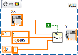
y = filter ([1 - 0.9495], 1, xx);
I have xx table in labview.
now I want to filter them even as in matlab,.
... anyone know how to do this?
Please help me...

MATLAB help tells you:
y = filter(b,a,X) X vector data with the filter described by vector numerator coefficient b and the denominator of the coefficient vector onefilters. If (1) is not equal to 1, filter normalizes the coefficients of the filter (1). If (1) is equal to 0, filter returns an error.
now take a look on LabVIEW IIR digital filters
-
low pass filter in labview 7.1
Hi all
I would like to ask about the low pass filter.
Is it possible to make a simple low-pass filter without any supplement on Labview 7.1.
We strive to connect a micro-switch in a DAQmx device, but the thing is, because the switch is somehow Earth-connected to an engine step by step, each time the engine is running, it will have peaks and spikes were interpreted as logic 1 in the labview. Since we have no treatment signal Add ons in the labview, we try to do it ourselves.
Thank you
Although suggestions are significant
But the solution has not been reached. So actually, we tried to change the analog to digital input in our DAQ hardware. I hope that the - top-of-10V-spike not to spoil our DAQ hardware. And it turns out OK. In the digital input, spikes has appeard not even once, and we think it does.
@ t06afre: thanks for the material made up the suggestion, but since it is a testbox.foobar.com that we, his isn't going to be easy to put in engines and unlikely capacitors supposed to do. The cable twisted pair is not a bad idea though.
We thought that the software solution filter would be the best (less time necessary and less messy) but is not as we have not thought of material assistance (R - C circuit, duuh) filter.
And on the 'minimum pulse duration' setting, is not only applicable for some DAQ hardware? CMIIW


Maybe you are looking for
-
I was running to the latest version of firefox on my laptop, but I think he was still running through a synchronization of the former. This laptop has been erased, and now I have a new. I can't get my only synchronized data, even when I install versi
-
Suddenly, without any intervention on my side the trash of the card disappeared completely from my account in TB. I can't delete messages more in the Inbox. I created a submap in the Inbox. Cannot delete card, that is. How to fix/restore this problem
-
Qosmio G10 - a problem with the cooling system
Hello Put on my G10-100 this morning and got the following message: "A problem with the cooling system has been detected. "Please turn off immediately and the return of serve. My other machine running and connected on toshibas website and found the n
-
EliteBook 8540W: updating graphics card on HP Elitebook 8540w
Hi peopleI have an elitebook HP 8540w , with graphics Nvidia Quadro FX 880 M, Win 7 x 64 Pro, Core i7 620 M.My question is: is it possible to Update the graphic card Nvidia Quadro K1100M or K2100M?At the level of the connector standards of advice and
-
Cannot reply, forward or come from an email using Hotmail. OS is Vista
As of Saturday, November 19, 2011, I had no problem receiving, replying or transfer or from emails using my Hotmail account. After starting my system on Sunday, November 20, 2011, however, I can receive emails, but I can't front, response or are cre