the thermostat control through DAQ card
Hi all
I'm trying to control a card DAQ (data conversion, DT9816) through LabVIEW. What I try to do is to 'one' send to one of the output ports when a temperature value falls a specific range and to send a 'zero' when it falls in the range. I tried to do this with a box structure. But when the condition is met, the computer send 'one' at the ports, but when he is not filled, it has not stopped 'a' sending. I have attached the code provided by the manufacturer of the DAQ (Dout Single.VI) card could you please send me an example VI for the implementation of the idea?
Thank you
Deniz
Why you still a while loop continuously send out a logic 0/1? He will continue to run until you click the stop button and of course the rest of the code is paused. A writing without a loop should be enough.
Tags: NI Software
Similar Questions
-
Acquisition of data using the DAQ card
Hello everyone
I need assistance with the acquisition of data of the generator of signals through DAQ cards. I plugged the signal to the SCB-68 generator where the analog inputs of the generator are connected to AI CH5 and AIGRND of the Terminal Board. Then the output of the block is connected to the DAQ card. The maximum sampling frequency of the card is of 250 kech. / s. The problem is for reason that I am not able to see the waveform on the labview. I looked at other examples to find the problem, I am, but I am not able to understand this. I want to be able to choose the sampling frequency. I attatched my code as an attatchment for you all to help me know what the problem is. Any suggestions will be appreciated.
There is no task! You have not specified any hardware (i.e. your data acquisition card) anywhere.
Here's a suggestion. MAX aperture. Find your DAQ hardware. Open a Test Panel. Implement a continuous sample of N Points to some sampling rate. Press Run and convince yourself that you get the data.
Now, while remaining in MAX, to create a task, using the same settings. Call for example something sensible ("MyFirstDAQTask" is not a good reputation).
Now, go back to your code. Eliminate the first two functions DAQmx. Wire a constant task to the DAQmx Start feature. See the little triangle down? Click it, and it should show you the tasks he 'sees', the only one should be the task that you created in MAX.
Note that 'Samples Visible' is now 'hard coded' in the task. To get its value back out, you need to put a property node Timing DAQmx after the task start and pull on the quantity of the sample, samples per channel (which, for reasons that escape me, is a Dbl, you need to convert to an I32 before importing it into the while loop).
Bob Schor
P.S. Thank you to join your code.
-
Programming of the remote control
I am able to program the buttons on the remote without problem but I have more than 60 deployed MD and would like to be able to program them all at once. Is there a way to the DMM to write an application of advanced task that will program the remote button?
Thank you
Al
Alan,
Here's a technical tip I wrote on the programming of the remote control through the
a HTTP mib. Just create a task advanced under the task system
for each color button. Test & check if it works on a single DMP first and
then send task for each color button to all of the DMP. Once it is
finished make sure you that you SAVE the configuration.
If this answers your question, take the time to mark this
discussion answered & rate the answer.
Thank you!
T.
******************************
You can use DMP MIBs to reconfigure the DMP Remote Buttons. VARIABLES ========= admin = DMP Web Account Username default = DMP Web Account Password a.b.c.d = IP Address of DMP dmm.company.com = FQDN of the Digital Media Manager(DMM) Appliance MIBS ==== ** Use the Following MIB to see the CURRENT Remote Mappings https://admin:[email protected]/* */:7777/get_param?p=*.*&init.pop_enable=false ** Configure Buttons RED https://admin:[email protected]/* */:[email protected]/* */[email protected]/* */Dwww.cisco.com%22 GREEN https://admin:[email protected]/* */:[email protected]/* */[email protected]/* */MD%3Dhttp://www.google.com%22 YELLOW https://admin:[email protected]/* */:[email protected]/* */[email protected]/* */_CMD%3Dhttp://www.yahoo.com%22 BLUE https://admin:[email protected]/* */:[email protected]/* */[email protected]/* */%3Dhttp://www.apple.com%22 ASSIGN A BUTTON TO CAST https://admin:[email protected]/* */:[email protected]/* */[email protected]/* */Dhttp://dmm.company.com:8080/etv-flash-webapp/app/etv_24_.htm%22 ** Use the Following MIB to see the NEW CONFIGURED Remote Mappings https://admin:[email protected]/* */:7777/get_param?p=*.*&init.pop_enable=false ** Save NEW CONFIGURED Remote Mappings on DMP -> Use the ADVANCED TASK to SAVE the DMP Settings. -> or Directly on the DMP using the DMP-DM Web Admin -> or HTTP MIB ie. https://admin:[email protected]/* */:7777/set_param?mib.save=1 https://admin:[email protected]/* */:7777/set_param?mib.save=1&mng.reboot=1
-
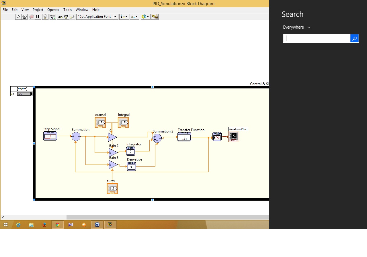
How to connect a simulation on the design of controllers to DAQ card?
Hi guys... I have problems about control and design on the way to the simulation I just do simulation PID and I can not to connect to the path of the simulation DAQ card in the control design (function)... can someone help me how to connect that?
Ayubi,
First of all, remember that the control and the Simulation has a PID in the Palette "control and Simulation > Controllers.
Then, to connect to a data acquisition card, you must use the DAQmx interface is there to connect. In general, National Instruments recommends allows you to deploy a controller a real-time system, but most likely your Windows computer should be good enough for your application. Please see the example of the expedition (in 2013):
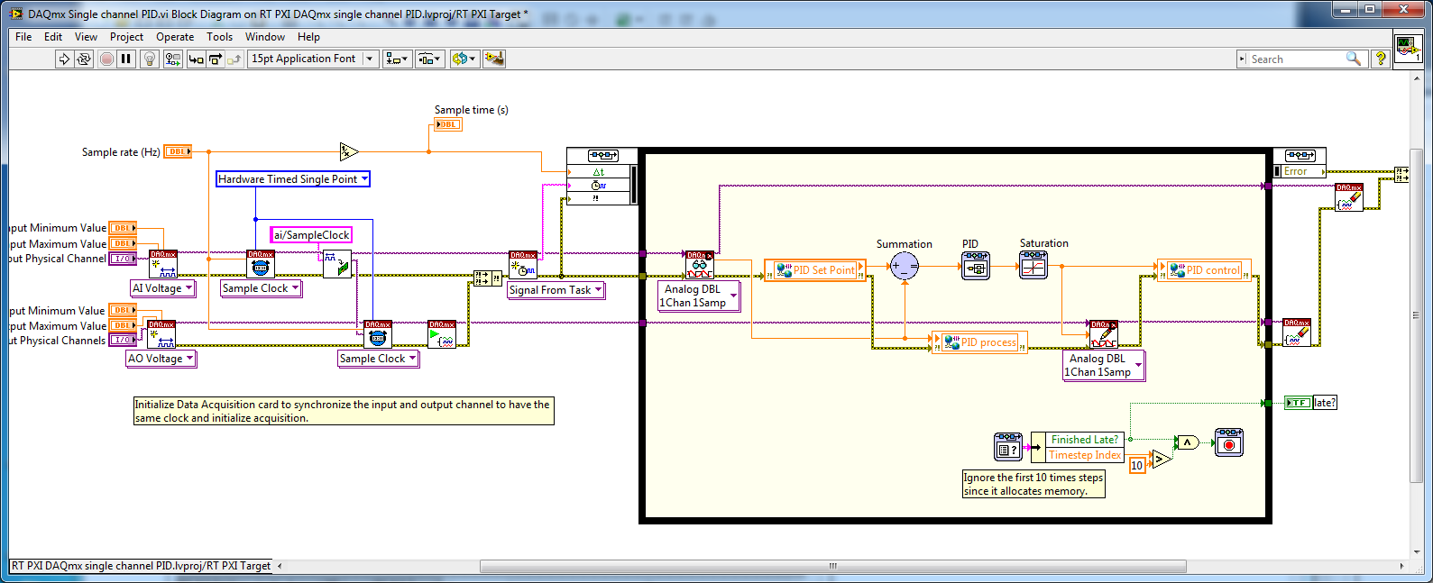
C:\Program Files (x 86) \National Instruments\LabVIEW 2013\examples\Control and Simulation\Simulation\Real - time\DAQmx\RT PXI DAQmx single channel PID.lvproj
If you don't have a LabVIEW Real - Time (RT), you can simply open the VI:
C:\Program Files (x 86) \National Instruments\LabVIEW 2013\examples\Control and Simulation\Simulation\Real-time\DAQmx\DAQmx single channel PID.vi
Remove the shared Variables in the code and he would be executed on a computer with a DAQ card.
-
Original title: Install the new NVIDIA GeForce GT 240 graphics card but now gets error message regarding the necessary to the old card drivers ATI Radeon.
I just bought a new computer from AMD PHenom II quad core Dell Inspiron with Windows 7 installed. For the graphics card, an ATI RAdeon 4200 on it there but I wanted a more powerful card and installed a NVIDIA GeForce GT 240 graphics card. The ATI Radeon is not delete because honestly, I could not recognize what it should look like and thought that maybe it was incorporated. The fine installed NVIDIA card and now shows as the graphics card used by the computer Information System.
My problem is that whenever I start my computer, I get an error message saying that the drivers for the ATI card are not compatible with the Catalyst Control Center. I think I need to disable the ATI card, but don't know how. Can you help me?
Dell Inspiron 570 is a desktop computer, the ATI Radeon 4200 is an integrated graphics card chipset usually equipped with laptops. Something is not here.
Go to dell support, enter your tag # and get the origonal system specifications.
You can uninstall anything about ATI through Add/Remove dialog
-
How display the waveform acquired DAQ card separately in wavefrom graphic
I NI 9239 DAQ card and it has four channels. I need to create a user interface graphic labview in which I need to display all the forms of four wave separately. If I select all four channels of the daq assistant and connect the waveform table all four waves are coming to overlap... I need separately for the treatment... what should I do?
Thank you and best regards...
Try this
-
How to give input to the DAQ card three times
Hi all...
How to assign three channels of entry (as Dev1/ai0, Dev1/ai1 and ai2/Dev1) DAQ card at the same time?
Rd,
Ganesh
BMETTENT wrote:
Hi all...
How to assign three channels of entry (as Dev1/ai0, Dev1/ai1 and ai2/Dev1) DAQ card at the same time?
Rd,
Ganesh
Use Dev1 / ai0:2?
-
selection of the daq card to get the angular position of 6 motors with encoder
can you suggest me best daq card to use 6 positions of engines as outputs using encoders attached to the engines. I'll use single window for each engine. Or what can I use a single window for all the coders of engines?
Hello Prabhakar7117,
You need a counter for each encoder. Because you are going to use 6 encoders, you should get a DAQ hardware with 6 or more counters. Take a look at the PCI-6624 or PCI-6602. Another option would be a CompactDAQ chassis with modules that are able to access counters. Take a look at them.
KB which cDAQ Modules can be used to access the counters of the shipped?
Best regards
Alina M
-
Hello
I use a M Series DAQ card (6229) multichannel and multipoint make reading and writing of waveforms, all synced to a clock generated on the 6229. Now I need to extend that to a "remote" (10 m) location and I was planning to use the Ethernet (9188 or 9184) CompactDAQ chassis or maybe 9144 Ethercat slave. Before I have buy and learn the hard way, I thought I would ask some advice:
My questions are:
(1) using the DAQmx can I access the IO on 9184 or transparent 9144 using a multichannel multipoint DAQmx task as I do for the PCI 6299 card?
(2) are all of these chassis supported if I use RT on the host?
(3) is the best way to synchronize and trigger the remote system to the host using a digital line between the 6229 plug-in and the chassis from a distance, and if so, how can I connect it to the chassis and set it as a sample clock?
Any help would be appreciated.
Hi AnthonV-
You make perfect sense. And, I am pleased to report that you can program your analog output task CompactDAQ to use a clock timed by material, like your M Series device. In fact, it is possible (and perhaps even likely) that the same code of OR-DAQmx you use for M-series can be used directly on CompactDAQ also long that the AO, relaxation and sources of timing and similar channels can be updated to point to your CompactDAQ chassis.
As I've mentioned before, please note that only the CompactDAQ USB chassis (except the cDAQ-9172) are compatible with the PharLap LabVIEW RT objectives. I don't know if this will meet your needs for a > extension of 10 m from the host system.
-
My speakers suddenly stopped working. I went to audio and I received a message sound card may be in use. The volume control does not appear atr from the bottom of the screen and when I go into properties, everything is gray.
Hi BarbaraEvanchik,
· What is the brand and model of the computer?
· Did you do changes on the computer before the show?
Follow the steps in the article.
How to troubleshoot sound problems in Windows XP
For reference: no sound in Windows
-
my sound keeps disappearing. I go through all the help and support the steps but still no sound. the volume control is all grey and says no audio device found. but the Device Manager indicates that all is well. What is the problem that I continue to have?
Hello
1. the troubleshooting steps are you referring?
2. don't you make changes on the computer before this problem?The following article might be useful.
No sound in Windows
http://Windows.Microsoft.com/en-us/Windows/help/no-sound-in-Windows -
Original title: error message
Whenever I turn on my computer (Windows Vista) I get the following error: "the Catalyst Control Center is not suppoerted by the version of the driver for your compatible graphics card. Please update your ATI graphics driver or enavle your ATI card using the display manager. "How can I do this? and do I do this?Hello
Update the driver may solve the problem. See the following article to install/update the drivers.
Update a hardware driver that is not working properly.
You can also download the drivers from AMD. Choose the appropriate brand and model of the device and download the drivers.
-
Original title: scroll of the mouse wheel only adjusts the volume. How to scroll through the pages again?
Using the wireless mouse (Silvercrest MTS2218-m with win 7 x 64) and scroll wheel is no longer made scroll page up and down in any program. Only, it adjusts the volume. How to scroll through the pages again?
Already checked the settings in Control Panel > mouse nothing obvious here to change this annoying feature. And have already uninstalled the driver for the mouse in Device Manager but no change. have also stopped and started several times laptop.
Close to the scroll wheel is a dpi button, which can also be used to pass
between normal mode and media holding for 3 seconds. In media mode
the volume control wheel and does not scroll.
Read the manual... ;-) -
Smart card reader does not correctly connect once the virtual machine is restored from sleep using the vmrum controls
Scenario is,
1. smart card reader is connected to the VM with card inserted in
2 initiate a prompt suspension of the VM toolbar
3. now to resume the virtual machine by using vmrun command into the host machine
WS t vmrun start xxx.vmx
Now, the recovery of VM but the smart card reader that was previously connected does not work properly in VM that is to say, sometimes after CV chip card reader driver is uninstalling and a few other times, chip connected to the drive is not available on a virtual computer
My requirement is after power, smart card reader can stay connected to the virtual computer with the already installed driver and the smart card.
Kindly help with this problem.
Host operating system: Victoire 2012 R2
The VM OS: win 10 x 64
Thank you!!
Dear all,
I had a work around for this problem. By adding "usb.autoConnect.device0 ="0xVID:0xPID"" this statement to the VMX file, solves this problem, that is, whenever the VM is wake-up by clicking on the link CV or using vmrun commands, it connects the unit in question automatically and it is charging correctly with his driver. Obtaining smart card detected after sleep\hibernate with no problems.
VID & PID is respective ID of the device that can be seen in the properties of the Device Manager "Device Instance path".
For more information about this, visit VMware KB: automatic connection of USB devices to the virtual machine power on
~ Surendra
-
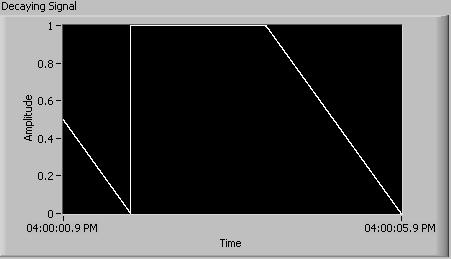
Output voltage continuous to the DAQ card provides a discrete signal
I'm looking at the exit of a continuous decaying signal as shown below.
(For now, let's assume that I must leave the Fs sampling frequency: 1000 and #s: 1000)
In the loop where the signal is generated, I inserted a block 'Wait (ms)' so that iterations would maintain the good timing. If this is not the case, the speed of the iterations would be too fast. Although, when I measure the output to the BNC connector, the actual output is in discrete steps, which depends on the speed of the iteration. (for example, for the signal preceding with freq = 1/4 Hz, the result would still be 1V for two seconds, 0, 5V for a second and 0V for a second, then repeat)
Is it possible to fix this?
Before I tried this method, I had used the output of Wizard DAQ, which had no need of me having to insert the "wait (ms). But the problem with this method is that there is a delay between when the program has sent a message and when the output BNC connector has received the signal.
I guess that the second method not released by discrete steps due to the buffer that is maintained in the wizard. I tried to have some sort of buffer to the first method, but could not because of lack of experience, I guess. If I could also, it seems that I could introduce a delay once again, which is undesirable.
Any help on this would be appreciated. I will attach a copy of the article that gives me bad.
Thank you.
Mike
As I said, the filter must be set up the EQUIPMENT. Just as an anti-aliasing filter on an analog input must be done at the hardware level, so a reconstruction on an analog output filter must be implemented in hardware.
Sometimes robust filtering is necessary, but in general a simple RC works very well. Google 'Filter RC' or "low-pass filter" to get examples and design equations. Often the hardest part only is coming with good places for mounting of all.
Mike...
Maybe you are looking for
-
I don't know how I changed my e-mail address, some opinions came on the keystrokes and I said yes. After that, I couldn't type anything. Somehow I'm back to normal, but now all my files just show a folder, no name. How can I get my back indicating th
-
Satellite Pro M40X does not work with battery
Hello I have toshiba satellite pro m40x laptop. It haves apromaly 11 months.In recent weeks, the laptop does not work with the battery.With the battery and the power running, if I turn on the laptop, it turns off after 10 seconds. If I only turn the
-
Current version (6) works to the identity of Norton safe?
I don't want to upgrade to version 6, if it doesn't work with 360 Norton identity safe. I know he had a problem with one of the improvements as soon as possible.
-
Hello I want to use shared variables (network or a single process, does not matter), to communicate on the same PC two exe. Everything works fine with the development environment. Things are not so good, if you use exe. I found this useful link on th
-
Can I transfer my data TEMP and TMP with a RAMDisk?
Hello I have a virtual drive on my computer Setup and want to know if I'll run any problems if I move my windows TEMP directory to it?