There is no inputs or outputs Assistant DAQ
During the last day, I lost access to the inputs and outputs on the DAQ Assistant. I followed the instructions posted here with no luck.
Some information:
I'm a cDAQ9172 with a series of modules to HAVE/AO/DIO/Relay operating. I also use a SCXI1000 with a NI1303 multiplexer thermocouple.
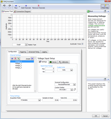
When I access channels of AI on MAX, I can read out very well. When I place a DAQ Assistant on a white VI, I can configure the channels very well (T/C type, range, etc.). When I build the Express VI, nothing happens and it returns the attached figure.
According to the instructions from the link above, I installed and reinstalled LabVIEW and MAX and updated with the latest version updates. I am now in a bind, because it does still not properly, as he had done in the past. I'm frustrated. Thank you!
Tags: NI Software
Similar Questions
-
Analog input voltage assistant DAQ
Does anyone know why theres error when you use two assistant DAQ (in a while loop at the same time) for reading of the analog input voltage?
There is not a problem if you use a wizard to data acquisition for analog input voltage reading simple.
If you get an error, wouldn't it useful that you have told us what it was, we may be able to explain it?
I'm guessing that you have error-50103, and if you look in the forums for '50103' (leave out the negative sign), it will give you the answer for this question has only requested thousands of times before.
-
Precise triggering voltage input and output generation in the DAQ Assistant
Hello
I wonder if anyone has come across a simular problem with the synchronization of input and output voltage. I use a box 11 LabView and NI USB-6259. I have been using the DAQ Assistant to configure the input and output channel. In particular, my task is to generate a single rectangular "pulse" as the output voltage to drive a coil and once the pulse went to get a signal from a sensor of magnetic field and get a power spectrum. This means that the order and the time during which the DAQ Assistant is used is extremely important. For example, the output voltage channel must be opened first for 2 seconds. Subsequently, the channel of input voltage must be open for 1 second, in which the sensor signal is obtained and post-processed. Only after these tasks are performed in this order he can can be repeated in a loop until the experiment is over. I don't know how to trigger data acquisition assistants (one for entry) and the other for the voltage output correctly. Y at - it a trick?
See you soon
Michael
Hi Dave,.
Thank you that I wired the error strings but the timing issue was unrelated to it. In the DAQ assistant, I simply had to choose the continuous aquistion of the 'samples' methods 'N-switch' for input and output voltage and all works fine now.
Thanks again
Michael
-
Hello
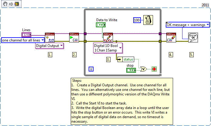
This should be very easy, but for some reason, I'm going to have questions. All I want to do has a switch control a digital output. I use a card NI 9742 Dsub (link), which should be capable of digital output.
My code, with a simulated map is attached. During the test I change the properties of the real card DAQ assistant.
Using this code, I can't get a DC output at all, my scope is all about 100mV. Using other cards, I have the analog i/o works fine, but for some reason, the digital output on this card isn't? In addition, if you look at the map, there are 8 green LEDs upward. I think that each specifies when an output should be enabled. When I turn on the switch, the corresponding led lights actually, but I can't measure a voltage? Is there a setting I'm missing?
I hope that makes sense. Thank you!
-secondary question: once it works, how can I change the output range. The specs say output 6V - 30V, but I do not see where to change that.
g e m e n i,
I looked at your code and noticed that it includes only a DAQ Assistant and a Boolean matrix of values to write.As it is currently, the VI will be only write a single value and then stop. In order to write constantly, you will need to place your code in a While loop.
If you see still no signal the evolution of 9742, consider opening one of the expedition DAQmx examples. You can find these examples in LabVIEW by going to help > find examples...
Try the following example: material input and output > DAQmx > digital generation > write hollow Chan.vi
-
Gap between the screws with the NI 9237 & Assistants DAQ
I have a set of scales attached to a NI 9237 module in a cDAQ 9174. I have two separate screws following the gross load cell output (mV/V). The two screws acquire through a DAQ Assistant. Two Assistants DAQ are configured in the same way, and yet they have different output values. Reads around 0.003 mV/V being not charged while the other reads 0.03 mV/V - an order of magnitude difference. Any thoughts on why this is? Thank you!
Thanks David,.
Finally, I followed him there down to a calibration offset null being applied to a DAQ Assistant and not the other. Is there a way to remove this discrepancy in the DAQ Assistant? It is not evident. I only noticed after DAQmx code conversion and managed to remove it it.
-
Configure 9401 to buffering of input and output
I have a compact DAQ (9174) and the module 9401. I found the example to configure the inputs and outputs separately. But when I try to apply that to my application, I get the error:
Device cannot be configured for input or output because the lines and/or the terminals on this device are in use by another job or road. This operation requires temporarily reserving all lines and terminals for communication, which interferes with the other task or the road.
If possible, use the control task DAQmx to book tasks that use this device before committing to tasks that use this device. Otherwise, uncommit or cancel the other task or disconnect the other lane before attempting to configure the input or output device.
Feature: 9401-0
Digital port: 0
Lines: 0, 1, 2, 3Task name: _unnamedTask
I tried using the example that works and adding just the bits and I think it has something to do with the fact that I use stored sample, but not sure clock output buffer. I found the sample output correlated and fundamentally changed than to generate a waveform, that I need. That part worked fine. But when I then tried to use the entry, which has not worked very well. The related example, I tried with line0:3 as output and input on the 9401 line7 and using the meter chassis as source is attached.
Is there something with exits/entries in the buffer that will not allow using both at the same time? or what am I missing?
Found my problem. The RESERVE has to happen just before the start of the task. If try to change the sample clock or anything after reserve, leads to problems.
-
USB & Firewire audio interface ports still work as input and output?
I guess everyone has to start somewhere, even if it is borne by almost everyone I would like to know the answer to my questions, perhaps with good reason, what I don't know is so if the USB ports unique connection and firewire on an audio interface function ALWAYS both as input AND output. In other words, whenever I read the information about the product on audio interfaces, no matter where I go, it is generally accepted that most people buy their audio interface for RECORDING. And so when most people talk about connecting their Apple computer, iMac or MacBook Pro, it is generally accepted, they turn to the USB as INPUT. That's all very well and good. But in my case, I want to use the USB port as output (not the taken mini) and go into an audio interface that gives me as a symmetric output signal that I can plug my amplified studio monitor (which has only a balanced XLR input). All of the examples I see with audio interfaces address registration and involve the use of the USB on the audio input interface.
So my question is: can one USB port I see on any number of audio interfaces always function both of the inputs and outputs? It takes, but if so, why does any site mention this fact and whey didn't they show in all the diagrams of the audio interface manual hook to studio monitors? I know what may be obvious to some, but as a user with the intention not to use a piano for a scene while but rather a keyboard/MIDI controller that is attached to the iMac to be able to use the virtual instrument software, I need to go to the controller to the iMac, then the iMac in symmetrical powered monitors. Do the balanced inputs of speakers requires more than a simple adapter to give the President a balanced input. But nobody talks about audio interfaces usually unless they talk about as a way into the computer to record. As for my situation? Why don't they include this example? And why should they assume that novice will automatically KNOW that the usb port, an audio interface will work as an output as if they never EVER mention this example or Setup? I guess it is to operate in both directions! But really, I'm crazy to wonder when no one never speaks or shows this configuration? He suggested I buy something similar to a UR22MkII of Steinberg, who has a USB port. Even the Steinberg site speaks only records and so using the USB key as input for use with the recording software. There is no mention of its use out the mac in balanced speaker entries, even in the manual. In fact, it is question is always true for every audio interface manual that I watched, even by other manufacturers! Why they all assume a novice like me (whose money is just as good as money from the experienced user) KNOW that? It's frustrating!
I know that this is not strictly a matter of logic, but I guess, in my view correctly, that a logic user community could be more appropriate to address my question for others communities. If I'm wrong, please help to re-send-the matter. Thank you.
Sound the interface itself that determines it can send and receive Audio or Midi... not the USB or FW port which both are devices of e/s...
All USB and Midi peripheral FW are inputs and outputs
All the USB and Audio FW are inputs and outputs...
All devices USB or external hardware with a USB port... can handle Midi and Audio... Some do... Most manipulate just Midi... or just Audio
The Steinberg UR22MkII manages Audio and Midi...
However, I do not recommend USB 2.0 audio devices... There are simply too many cases, problems and questions after the major updates for OS X with such devices especially when they are class compliant (IE without driver), even if the UR22MkII Steinberg is supposed to be compatible 10.11...
View the other may vary... because it's just a personal opinion based on my past experiences both in my studio... and based on the many issues presented here and elsewhere.
I'm sticking with Motu equipment for all my Audio devices... and I use iConnect devices for my Midi needs...
-
Synchronized analog input and output on myRIO
Hello!
A brilliant new myRIO just landed on my desk and I'm looking forward to learn how to use it.
I have a question about the ability of the default FPGA personality.
Is really similar synchronous HW in and output possible? Can configure you the necessary trigger and clock routing from within VI RT? To say ~100kS/s?
I need to delve into a FPGA design to achieve this?
Thank you!
You will not be able to get your RT loop to run reliably at rates greater than 5 kHz, and we generally do not recommend trying to control I/O faster than 500 to 1000 Hz. This isn't a limitation of the default personality himself, it's just that some tasks are better suited for the OTR and some are better for the FPGA (it is important to understand when developing an application on the myRIO). Synchronization and the output of ~100KS/s signals are something that you have to do on the FPGA.
http://www.NI.com/Tutorial/14532/en/
There are some good tutorials in the link above. They use the cRIO instead of the myRIO but the functionality is basically the same. The biggest difference is that you won't have to add modules to your project, because all the inputs and outputs of the myRIO are fixed and must fill out automatically when you add a FPGA target to your project.
-
Call Assistant DAQ of Labview code
Hello
How can I call the DAQ Assistant dialog box
from Labview code, as well as a program compiled with Labview runtime?
Now, I can set the Express Assistant DAQ vi in the block diagram, but cannot be changed during execution.
But the configuration of data acquisition is not static. The end user must change.
A similar dialogue is used inside the Measurement & Automation Explorer with a task global DAQmx.
Can I call this dialog of Labview?
Peter
There is a way to call the DAQ Assistant of MAX of Labview code to create or modify a task DAQmx: Screw Wizard DAQmx LabVIEW
-
Synchronization of the inputs and outputs with different sampling frequencies
I'm relatively new to LabView. I have a NOR-myDAQ, and I am trying to accomplish the following:
Square wave output 10 kHz, duty cycle 50%.
Input sampling frequency of 200 kHz, synchronized with the output that I get 20 analog input samples by square wave, and I know what samples align with the high and low output of my square wave.
So far, I used a counter to create the square wave of 10 kHz, display on a digital output line. I tried to pull the document according to (http://www.ni.com/white-paper/4322/en), but I'm not sure how sample at a different rate than my clock pulse. It seems that this example is intended rather to taste one entry by analog clock pulse. There may be a way to create a faster clock (200 kHz) in the software and use that to synchronize the analog input collection as well as a slower 10 kHz output generation square wave?
I eventually have to use the analog inputs to obtain data and an analog output to write the data channel, so I need the impetus of the square wave at the exit on a digital PIN.
How could anyone do this in LabView?
Hi Eric,.
All subsystems (, AO, CTR) derive from the STC3 clocks so they don't drift, but in order to align your sample clock HAVE with pulse train that you generate on the counter, you'll want to trigger a task out of the other. I would like to start by a few examples taken from the example Finder > Input and Output material > DAQmx. You can trigger GOT off the train of impulses, start by Gen digital Pulse Train-keep -you probably already use a VI like this to generate 10 k pulse train. AI, start with an example like Acq Cont & chart voltage-Ext Clk - Dig Start.vi-you'll want to use the internal clock so just remove the control of the "Source of the clock" and it uses the internal clock. From there, simply set the "Source of the command" either be the PFI line generates the meter, or ' /
/Ctr0InternalOutput '-assuming that you are using the counter 0. You'll want to make sure that the start of the task HAVE faced the task of counter I is ready to trigger off the first impulse. They should be aligned at this point. For debugging, you can use DAQmx export Signal to export the sample clock - you can then brought the train line and the PFI pulse to make sure that they are aligned.
Hope this helps,
Andrew S
-
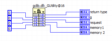
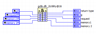
Make sure that wire you all the inputs and outputs of your node library function call?
This document says "make sure that wire you all the inputs and outputs of your node library function call.
But all the terminals on the right side of the call library node considered "outputs" referred to in the foregoing statement?
This same document continues to show the right way to allocate memory with this illustration and in the illustration, the right "outputs" are left without junctions.
Am I right in assuming that the only terminals that count as outputs, those who use the code of the DLL (modify) as output? If it is true, then all other terminals output associated with the values entered alone so don't really account as outputs, correct?
In the parameter call-library configuration screen there is a "Constant" check box and the help that he wrote "indicates whether the parameter is a constant." What is this box? for me in the setup of the DLL call
Finally, assuming that a call from the DLL that is supposed to write in these five outputs, is it legitimate to use constants like this to book a space of memory for the output values?
How about if local variables associated with the output terminals are used instead?
Despite the linked document, it is necessary to connect the corresponding entry for simple scalar output parameters (for example a digital). LabVIEW automatically allocate memory for them. If you do not want the entries for all the output wire anyway, there should not be no difference between a constant and a local variable; I would use a constant to avoid useless local variables.
For settings that are only entries, there is not need to connect the outlet side. It's a bit simplistic since all parameters are entered only and get one result (other than the return value), you pass a memory address and modify the content to this address, but LabVIEW manages this dereferencing pointer for you. If you want to really get into the details, learn more about pointers in C.
The "Constant" check box acts as the qualifier "const" on a c function parameter. It tells the compiler that the function you are calling will not change this setting. If you call a function prototype includes a const parameter, then you must mark this as a constant parameter when you configure the call library function node. Otherwise, I wouldn't worry on this subject.
-
Digital input and output problem
Hello:
I do a test for digital i/o:
for a table of the digital signal to an output of data acquisition in the digital input to detect the output signal.
(bascially, it's like a loop that goes outside the material)It's pretty simple, as shown in the attached fichier_1.
It works well.
The manual light switch controls, which means that inputs and outputs are ok.Then I went on the low level DAQ for better speed, as in attached fichier_2.
But it does not work. Especially when I pressed stop to abort the loop, an error has occurred:To speed up, I went to the low-level data acquisition as the fichier_2 attached.
But it does not work. Espeically when I press the "stop"button to exit the loop, the error occurs.Possible reasons:
Requested value is not supported for this property value.
The value of the property may be invalid because it is in conflict with another property.Property: SampTimingType
Asked the value large clock
You can select: on requestI don't understand why the sampling time has a conflict here.
(It is probably just something very simple in data acquisition, but I checked a few examples and did not find a clue).
Hope someone can give me a suggestion.Ultimately, my goal is to make the attached file_3.
In this one, I generate a digital output, and then lead to the entrance.
Then I can take it as a signal to trigger my other task.Note:
I use a similar conti signal to control one of my camera.
I need to sync it with my another task.
So I think to generate a digital output (which share the same clock as the signal similar to the data acquisition device), then put it in one of the digital input.
By detecting this digital input, I can trigger my task and synchronize with this signal similar.
My camera's USB-6211.
I am aware of the latency of USB, but once the value is a constant value, then the synchronization is always good for me.
Actually, I was using an analogue at the entrance of the to do it before, it may work, but the synchronization error is too big for me.
I need to do some calculations/judgment for this analog value, which makes the time difference varies.
So I'm trying digital entry now and I hope that the digital input can trigger my task with a stable latency.Thank you very much
Have you looked at the specs? It clearly states that the digital I/o is a programmed software. You have not any hardware clock at all. The best rate that you could possibly achieve is around 1 kHz and which would have a considerable jitter the nature of non-determimistic of windows.
-
Impossible to get assistant daq to appear
Hi all
I am currently using student Labview 2009 edition, I also installed NOR-DAQmx 8.8, I don't have that a little project to do with the acquisition of a voltage using a DAQ6008.
I'm trying this project: http://www.me.umn.edu/courses/me2011/labview/LabVIEW-thermistor.pdf the problem is that Assistant DAQ is nowhere to be seen in my Labview program.
Is there something that I missed?
I searched the palette DAQ and its certainly not there.
Any help is appreciated!
Hello Marko,
The problem is that NEITHER-DAQmx 8.8 is not supported by LabVIEW 2009. You must download and install DAQmx 8.9.5 or later for LabVIEW 2009 supports. I recommend the latest version of NOR-DAQmx:
NOR-DAQmx 9.0.2 - Windows 2000/7 x 64/7/Vista x 64/Vista/XP
Let me know if you encounter other problems.
-
synchronize the inputs and outputs on the USB-4431
Hello
I have an application that needs to send a signal on the USB-4431 and then capture it with an entry on the same device.
Aware that I use two tasks to do this, one for input and one for output. I discovered that a trigger (on the RTSI bus) can cycles of sending/capture sychronisé departure operations so that it can be a constant offset between the captured signal and the output signal.
Unfortunately, the code I found is for Matlab. I can't find an equivalent for it in the C API of NIdaq. The method is described here; http://www.mathworks.in/help/daq/synchronize-analog-input-and-output-using-rtsi.html.
What I can't understand is how to implement this on the analog input:
ai.ExternalTriggerDriveLine = 'RTSI0';
Can someone shed light on how to do it?
The rest of the things described here, seems to be feasible with a normal trigger:
ao.TriggerType = 'HwDigital';
ao.HwDigitalTriggerSource = 'RTSI0';
ao.TriggerCondition = 'PositiveEdge';
Thank you
Nirvtek
You can synchronize the HAVE and AO by sharing the start of relaxation between your two tasks.
Choose one of your tasks as the "master" and the other to be the "slave" (any).
Set up a trigger to start of digital dashboard on the task of the slave, and set the source of the trigger to be the trigger of the master's departure.
Assume the following:
The name of your device is 'Dev1 '.
I is the main task
AO is the task of the slave
Here's what you would do to sync the two:
(1) create the tasks I and AO in order that you want to
(2) set up "timing" on the tasks of HAVE it and AO (you choose the sampling rates must be the same or power-of-2 many of the other (for example 100 K, 50 K, 25 K, 12.5 K, etc...))
(3) configure your slave (the task of AO) task to have a numerical advantage start trigger and make the source is the trigger for the start of the task of the master (the task to HAVE it). In our case, "Dev1, AI, StartTrigger.
(4) write data (a sine wave, presumably) to your task AO
(5) start the task from the slave (the task of AO). The task of the AO is now in the 'Started' State, but given that you've set up a digital trigger early, it won't actually generate data until he sees a numerical advantage of 'Dev1, AI, StartTrigger.
(6) to start the main task (task to HAVE it). The task of the AI does not have a trigger digital early, so the software will immediately generate a start trigger, which also causes a numerical advantage on "StartTrigger/AI/Dev1", which causes the task AO start at the same time.
7) read your job to HAVE.
You will notice a few 0 at the beginning of your data to HAVE. It's a result of something called "Filter Delay" and it is an inherent characteristic of all DSA devices - see the manual to use DSA and this article for more information on what is and how to cope.
I hope this helps.
EDIT: I just noticed that you pointed out an existing C example. It's exactly what you want. I don't know why you have a resource error booked - I tried it myself and (after changing the AO will of +/-10V to +/-3 .5V), it works beautifully. Try to reset your device to the MAX (or DAQmxResetDevice() of your program)
-
Why not USB-6509 allow setting input and output on individual ports?
I have one of the new USB-6509 (96 digital i/o channels) commissions. It has 12 ports for every 8 bits. The manual says that you can define the inputs and outputs on a per port basis. When I read an 8-bit port that I find it clears different ports that I put in place to be digital output. They seem to be grouped into 3 groups of 4. 0-3, 4-7 and 8-11. When I read from any single port within this group it erases the other ports in this group that I try to use as exits. The result is that I can put only input and outputs in groups of 4 ports. Unfortunately, we have built custom hardware based on the assumption that we could control the inputs and outputs on a basis of port by port. I see this problem as well with my LabVIEW 7.1 program (see table), as well as the measurement and Automation Explorer. Is anyone out there seen this problem with the USB-6509? Anyone using it with success? I also notice strange problems with power on, but I have yet to understand the model. IM wondering if I have a defective material or maybe this new material still has problems. I tried NIDAQ 8.7.1 and 8.8. Same problem with both. Thank you.
Thanks for the replies. It was determined that the USB-6509 we have has a hardware malfunction that is causing the ports to interfere between them. We are return to OR for repair or replacement. For now, we used a PCI-DIO-96, which works correctly. Thank you, Andy
Maybe you are looking for
-
pop up every few seconds: "Software Updater, 0 available Air, c software updates."
This 'Air' software appears constantly, very annoying. I am an 80 year old NOVICE and don't know fair terms for the problems of PC and functions. Thank you, Fred
-
NEVER buy a Lenovo product again! [Y570]
I got my Lenovo Y570 since December 12 or more. Since then, I've had hundreds of screens blue and some of them resulting I completely reinstall the operating system. So instead use the recovery partition, I used my own copy of Windows 7 Ultimate x 64
-
looking for a file in the disk
Hello and greeting to your friend, I'm looking for a command or a small program that displayed the files by their names in directories and returns a Boolean value, true if the file exists and, if mistakes. Thank you
-
How to I correct a mistake "the user profile Service impossible journal on" on my user.
I have 4 users, this user is an administrator. Problem is when you try to open a session.
-
Cannot get audio or speaker to work taking
Had to "Refresh" not restore my computer lost more additional applications. Assumes that the data is still there, but in some applications too fragmented to use. I can hardly keep anything on my computer today so... However the audio speakers wil