Analog input voltage assistant DAQ
Does anyone know why theres error when you use two assistant DAQ (in a while loop at the same time) for reading of the analog input voltage?
There is not a problem if you use a wizard to data acquisition for analog input voltage reading simple.
If you get an error, wouldn't it useful that you have told us what it was, we may be able to explain it?
I'm guessing that you have error-50103, and if you look in the forums for '50103' (leave out the negative sign), it will give you the answer for this question has only requested thousands of times before.
Tags: NI Software
Similar Questions
-
Using the DAQ USB-6009 meter and an analog input voltage at the same time.
Hello
Currently, I'm reading the two channels of voltage with the USB-6009. It happens that one of the channels is the output of a digital coder, and it would be much easier to use it directly to the PFIO entry that is defined as a counter. The problem I am facing right now, it's that I can't use the DAQ Assistant to use the analog voltage to a channel and the digital channel counter at the same time. Once I put the DAQ Assistant to read the input from analogue voltage, I won't be able to add analog inputs. And as I put the DAQ Assistant to use the PFIO as a counter, I can add more entries to read analog voltage is.
I wonder if it is possible to solve this problem using the lower level data blocks? Another solution would be to read two channels in analog input voltage and that the use of Matlab to process data resulting from it, since I was not able to do the counting to work simultaneously with the acquisition in Labview to impulses.
Hope you guys can help out me.
Thanks in advance.
Using a simple wizard of DAQ is incorrect. You need one to acquire analog inputs and one for the meter.
-
Cut-off for the 6008 analog input voltage
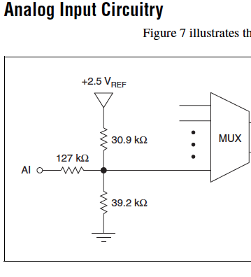
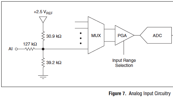
I am using the analog inputs NI USB-6008. The specification says they have a 144 k ohms input impedance. But it does not say what is the cut-off voltage. If you leave a disconnected and measure the voltage you will get 1.4 volts. So I guess it's the cut-off voltage, but it is not spec'd.
Someone agree that these Amnesty International isn't terminatied by 144 k - ohms to 1.4V? Is this in the documentation somewhere?
Figure 7 on page 16 of the NI USB-6008/6009 User Guide and specifications shows the strange input of this unit circuit.
Lynn
-
Limit NI9215 analog input voltage range
Hello
I use a NI9215 (mounted in a cdaq 9174) to acquire a voltage signal. I want to keep the tension as an integer and then later convert it to a voltage in the script of Fortran. To do this I need to know the relationship between integers and tension. If I use an unsigned integer I 0 is-10 for example (numbers aren't important as long as I know what they are).
I tried to taste a voltage signal (see the attached vi), where I have limit vmin and vmax at the return of V-10 and + 10. When I have a voltage outside this range, waiting for the signal to saturate at-10 or + 10 V, but this does not happen. I generally get +/-10.4 V which figure is the maximum range. This range would have been ok if it was exactly +/-10.4 V but it varies from something on the order of 0.5% between the different channels I use.
Is it not possible to set vmin and vmax that I'm trying to do and if so, what is then the point of vmin and vmax?
Concerning
PAL Egil
Hi pal_egil-
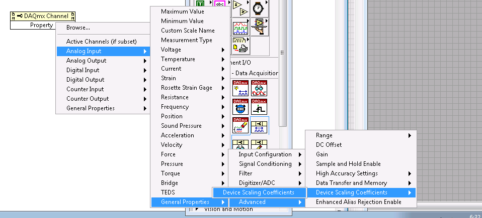
I guess you are trying to save time processor or (perhaps more likely) storage space by resizing the data yourself. I suggest that you use the version of DAQmx Read 'no'. This will give the most fundamental data type available and will save processing time (because it will not be scaling of tension and then re-scaling to an integer value simple on a linear scale of your application) and storage (because you will be able to store a single value of 2 bytes for each data point of your device).
So these unadjusted nationwide tension later readings, you'll also want to connect the device scaling coefficients for your module. These are accessible from the property of DAQmx channel node in LabVIEW, and a description of how to apply them to lectures unadjusted using LabVIEW for NOR-DAQmx.
I hope this helps.
-
Hello
The data entry in LabVIEW by my USB-1208LS is accurate, but the analog input voltage values are quantified (there are only a few repeating values: 0,691 0.696 0,701 0.696 0,701 0,691 0,691 0,691, etc..). I am able the tensions of four photocells, propelled by the + 5V of USB-1208LS. Each cell is measured in a different channel using the differential input mode. Is it possible to fix the quantification of data?
I don't know if it's a problem of LabVIEW, but attached is my diagram, in the cases where I'm not seized the tension properly.
Thank you in advance.
On the input range, the resolution of this device is about 5 +/-10 V mV, which is exactly what you see. The resolution is established by calculating the length of the total voltage range (20 V) and dividing by the number of steps or bins the A/D converter on this beach (2 ^ 12 = 4096). Yes, resolution = 20/4096 = 4.883 mV.
To get the best resolution, you will need to use a smaller range (if your signal wil fits into a smaller range) or get a DAQ hardware with a higher resolution, for example a 16-bit converter, or 24-bit.
Lynn
-
6008 analog input - invalid values
Hello
Does anyone know how the analog input voltage 6008 invalid handles? Specifically, what happens if the circumstantial channel is configured for a 0 - 10 range v and a voltage negaitve, (-19.0) volts is placed on the analog input?
I use the library, C/C++, OR-DAQMx library. The call that I use to set up the port of AtoD is:
DAQmxErrChk (DAQmxCreateAIVoltageChan (taskHandle, AINPSTR, "", DAQmx_Val_Diff, 0,0, (float64) s_dMaxAnalogInputVoltage, DAQmx_Val_Volts, ""));
where: s_dMaxAnalogInputVoltage = 10.0;
and
DAQmxReadAnalogF64 (taskHandle, 1, 1.0, DAQmx_Val_GroupByChannel, values, 5, & not read, NULL);
to read the circumstantial.
What will happen if any illegal input voltage is applied. I know that everything is a wide range, so I don't talk about something like -60 to + 60 volts.
Thank you
-Neil shore
These specifications are in the datasheet of the product - link to it in the product specifications of the page tab.
And no, there is no error generated when the input is out of reach. Scaling the proper entry so that this doesn't happen. or if this is the case, your software recognizes that is higher than expected.
-
Issues of analog input DAQ-6008, voltage not zero to pin when you are offline
I use the 6008 NOR-DAQ to produce a series of tensions and then read a sense resistor using the analog input (CSR). I noticed that my analog input gives me 1.3 V, when I probe it (compared to the mass of the device), when it is completely disconnected. This changes the reading to give me a different measure of sense than expected resistance.
Why is my pin for analog input non-zero? Any help would be appreciated. Thank you!
The 1.3 V is expected. The USB-6008-and-6009 case have the strangest input of the world circuit. The input impedance is approximately 144000 ohms terminated in 1.4 V. check the document User Guide and specifications.
Lynn
-
Several analog inputs seem to change any of the other (details DAQ: 2120 BNC and 6062E)
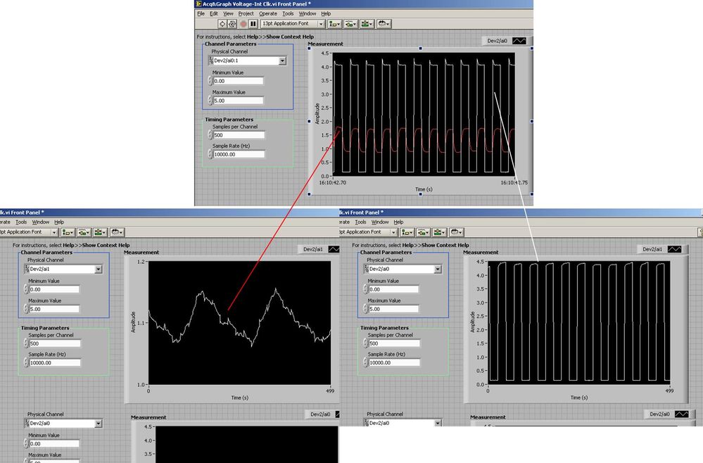
I use the BNC 2120 DAQ board connected to the data acquisition card 6062E to record two analog inputs. An entry is connected to ai0 and the other at ai1. Example vi: "Acq & graph int clk tension" has been used to measure the two entries with the value read NChan NSamp vi (channels being dev2 / ai0:1). The output is the top graph in the image. However, this seemed a bit strange to me that one of them should be modulating with a different frequency. When I record both entered individually (two in low pictures) they are indeed different since the entries shown in the top graph.

Why this would be the case, and how can I overcome this to measure the real signals?
Thank you!
The E series card takes the samples as soon as possible. Thus, for example,.
If you have 16 analog input channels but you only read of
channel 0 and 1, the map will show the channels 0 and 1 right
After and then wait 14 'ticks '. What's that little run-in
the origin of the afterglow.
I think you can get the card to wait a certain
number of ticks with a property node. I have attached a screenshot. You
can find the property node in the palette of functions >
Measurement of e/s > NOR-DAQmx > node Timing. Expand it
Property node so there's two entrances. The properties are in
Left click on the node and going more > converted >
Its properties delay units and sampling clock delay and delay that
you want.If the phase is important so the above is not the best
the option because it causes a delay in phase. So, if you need true simultaneous
sampling, then you will need different hardware. The S series is everything
simultaneous sampling.Or, rather than the Delay property and delay units, try the Rate property
find more > converted > rate.If this is not
work either, you can move the second signal source to, say, AI8 and
Connect everyone to the ground. Readings for these, but just do not take into account
the data. In this way the ADC will sag to the ground at the time where that can happen
the second string in the way so that you should not see this frequency
ghosting on the other channel. -
6225 PCI residual voltage in the analog input channel
Hello, I'm new to the Forum and just start working hands with NI hardware/software/etc.
I use MAX (differential setting) to monitor an input channel analog (ai71) through a PCI-6225 card with an SCB-68. The voltage displayed in this MAX sometimes regular 10.6 volts and sometimes intermittent noise 0 to 10.6 volts or vague angular. I watched the disintegration of noise and waves to zero. The voltage displayed in MAX is (seemingly at random) changes when a voltmeter is used to measure the voltage between pins 1 and 35 (with no wire signal)
When an external square wave (2.7 volts DC) is applied to the pins 1 and 35 in the SCB - 68 the value in MAX is dominated by the 0 - 10.6V 'noise', while a voltmeter between pins 1 and 35 simultaneously shows the square wave.
Any suggestions? Thank you in advance.
If you dig into the data acquisition specifications, input voltages must be referenced to the mass of AI or you may damage the Board. Have a good read of this article: wiring field and considerations of noise for analog signals. Since you're probably dealing with a differential signal with no mass, what you want to do is to add resistance on each side of the signal to ground. This article recommends until 100kOhm 10kOhm resistors.
-
Acquisition of data NOR-9205 Assistant set up range of input voltage
How to configure the module NI9205 to use the +/-200mV input range.
I use a custom scale, and it seems that I can not get an accurate reading. I use a shunt current of 100 Ma (max 10A). So I custom balance setting to have 100 x + b. The current flowing in the device is 2 amps and I get a reading of 12-13 amps after custom scale. Now I think the module is configured to sample for the entrance of 10V and I get an error of resolution.
Hi therbert
Since your custom scale is 100 x, to work on the beach of +/-200 mV to your NI 9205 module you must configure your input signal of maximum and minimum range for +/-20 respectively.
According to the equation: Range.max * scale.slope = 200mV * 100 = 20V
This will automatically configure to the scope of the module +/-200 mV to verify you can access the channel DAQmx property node and look for the analog input > General Properties > advanced > Range property, this will let you know in what range is the functioning of the device.
Concerning
-
My computer recognizes my cRIO-9002 but not the analog input NI 9205
Hello
I work with a unit 9002 cRIO and a NI 9205-analog inputs. When I check if my computer recognizes cRIO in Measurement & Automation Explorer, everything is OK, I have the cRIO with all its software and ports.
But when I am using the wizard DAQ in LabVIEW, I click on "data acquisition-> entries-> voltage->...» "and he said:"no supported device found ".
I searched through the forum, I installed all the new versions of the software and drivers, and I tried with real-time or labView with nothing.
Do you know where is the problem?
Thank you!
Hi xavgu
You won't be able to use the DAQ Assistant to acquire the data of your cRIO. Try to do is like trying to flyfish with a bottle opener, which is totally different things.
To get data in the cRIO you must first program the FPGA to read data in the module and then transmit data to the real time controller, which can either logg data or send it in turn via TCP/IP to you Windows host. Unfortunately the 9002 cannot manage Mode Scan, which would have made it easier for you.
Please take a look at these links:
Getting Started with CompactRIO and LabVIEW
Getting Started With LabVIEW FPGA 8.x
Best regards
David
NISW
-
Frequency measurement of analog input using DAQmx C APIs on SMU-6341 map
Hello
I use Linux DAQmx and attempt to measure the frequency of analog input using the map DAQ SMU-6341.
There is an ANSI-C frequency measurement example:
/ usr/local/natinst/nidaqmx/examples/ansi_c/Analog_In/Measure_Frequency/Cont_Freq-Int_Clk-SCXI1126
However, the call to DAQmxCreateAIFreqVoltageChan results in the following error:
DAQmx error: selected physical channel does not support the type of measure required by the virtual channel you create.
Create a channel to a type of measure that is supported by the physical channel, or select a physical channel that supports the type of measure.
Property: DAQmx_AI_MeasType
Required value: DAQmx_Val_Freq_Voltage
Possible values: DAQmx_Val_Current, DAQmx_Val_Resistance, DAQmx_Val_Strain_Gage, DAQmx_Val_Temp_BuiltInSensor, DAQmx_Val_Temp_RTD, DAQmx_Val_Temp_Thrmstr, DAQmx_Val_Temp_TC, DAQmx_Val_Voltage, DAQmx_Val_Voltage_CustomWithExcitationTask name: _unnamedTask<0>
State code:-200431
DAQmx does support the function of the frequency on the map 6341, or should we use examples of voltage and calculate the frequency manually?
Frequency of HAVE it is a type of channel that has been supported only on the SCXI module name of the example.
You will need to use a voltage input channel and calculate the frequency manually for your device.
-
PXI-6071e offset drift on the analog inputs
Hi, I have three cards PXI-6071E, sitting in a PXI-1042 chassis that is controlled by a computer with windows XP. The 6071Es are connected to the SCB-100 break out boxes that are wired to a pannel of BNC female Panel Mount on twisted pair.
I noticed that all of my analog inputs will drift around-10 V to + 10 V if they are not connected to what whether forcing them to a certain tension. This has always happened. We also see a bit of crosstalk between channels. For example if I open a panel of test in the measurement and automation Explorer I can watch the voltage read on the drift tickets through their full range, and alteration of the signals on nearby channels will appear on the channel, I am able.
Is this just standard behavior and to predict? Is there something more I could do to minimize this drift and crosstalk? I am trying to reduce noise in my system so I figure optimize my DAQ could not hurt.
Thank you
With nothing plugged into the catch to high impedance, drifting you see is quite normal. The front end of the circuitry builds up a charge, crosstalk is proabably due to the multiplexer input (did not check but I think that the 6071 has a) transferring the load to the other channels when they are analyzed.
Search the Forum of ghosting, you will find related discussions.
-AK2DM
-
Properties assistant DAQ does not open
We use version 8.0.1 LV with daqmx version 8.7.1. Win Xp with a PCI-6025E, SCB-100 card is attached. I can measure the thermistor in the SCB-100 in the measurement and automation for the hardware seems to work OK. The problem is to use Daqmx in LV I am following the tutorial at http://zone.ni.com/devzone/cda/tut/p/id/2744 . When I drop the Daq Assistant on the block on that diagram it does not open the property page for me to configure an analog input, double-click don't work, simple click and selecting Properties does nothing. In the measurement and automation, I can create a task and he launch the daq - mx box and setup of measurement with the PCI-6025E. Probably a setting issue somewhere, any ideas?
See this discussion and this one.
Hope this helps
-
What is the minimum response of analog input, through DSP online, output analog time?
Hello experts!
I want to know if it is possible to get a very quick response latency (~ 1 ms) sound recording (analog input), through online registration (DSP online), the presentation of his (analog output) processing, by using the DAQmx programming codes. My system of NEITHER includes NOR SMU 8135, SMU 6358 DAQ Multifunction controller and SMU 5412 arbitrary signal generator. I also have access to the latest version of Labview (2015 Version) software.
My project is on auditory disturbances, which inovles record vocalizations, manipulating the recorded vocalziations and then present the manipulated vocalizations. My current idea of how to achieve this fact triggered output voltage after reading the input using DAQmx Read samples. DAQmx Read output is filtered online and then passed as input for the DAQmx writing for analog output. For purposes of illustration, examples of code are presented below. Note for simplisity, codes for the trigger part are not presented here. It's something to work in the future.
My question here is If the idea above should be reaching ~ 1ms delay? Or I have to rely on a totally different programming module, the FPGA? I am very new to Labview so as to NEITHER. After reading some documentation on FPGA, I realized that my current hardware is unable to do so because I do not have the FPGA signals processing equipment. Am I wrong?
Something might be important to mention, I'm tasting with network (approximately 16 microphones) microphones at very high sampling rate (250 kHz), which is technically very high speed. Natually, these records must be saved on hard drive. Here again, a single microphone is shown.
I have two concerns that my current approach could achieve my goal.
First, for the DAQmx Read function in step 2, I put the samples to be read as 1/10 of the sampling frequency. It's recommended by Labview and so necessary to avoid buffer overflow when a smaller number is used. However, my concern here associated with the latency of the answer is that it might already cause a delay of 100 ms response, i.e. the time to collect these samples before reading. Is this true?
Secondly, every interaction while the loop takes at least a few tens of milliseconds (~ 30 ms). He is originally a State 30 late?
Hey, I've never used or familiar with the hardware you have. So I can't help you there.
On the side of RT, again once I don't know about your hardware, but I used NOR myRIO 1900, where he has a personality of high specific speed for the RT where I can acquire the kHz Audio @44 and process data. Based image processing is ultimately do the treatment on a wide range of audio data you have gathered through high sampling frequency and number number of samples as permitted by latency, please check this .
I lost about 2 weeks to understand host-side does not work and another 2 weeks to understand the even side of RT does not work for online processing (real time). Then, finally now I'm working on FPGA, where the sampling rate is 250 kHz (of course shared by multiple channels).
The complex thing with FPGA is coding, please check if the filter you want is given below as labview automatically generates some codes of some filters.
Most of them will work in 1 SCTL IE if your target has 40 MHz clock algorithm will run in 25 ns. That's what I was looking for, I hope you

See you soon... !


Maybe you are looking for
-
"Jiggly" videos on different Web sites
It started suddenly two days ago! So far, the videos played perfectly. I have the latest version of Flash from Adobe and Mozilla. Suggestions welcome!
-
On my laptop, conversion of Windows 8 to 10 was fine and Thunderbird has worked without any problems. On the computer of my wife who was on Windows 7, Thunderbird does not work. Thanks to this forum I could check that all emails and addresses etc. ha
-
HP pavilion p6000 series model p6805w windows7
PC won't start not closed down my hp Pavilion series 6ooo & the pc recover not. the lower left corner of the motherboard has a flashing green light, I also think that the battery poped when I tried to restart
-
Hello world I am installing a SPA9000 / SPA400 phone solution with 6 SPA942 extensions. I got all the boxes, connected to the network and I can set up the units via the wizard or the web interface. My problem is that for some reason that I can't co
-
Media Player will not play DVD - analog copy protection error
Windows7 operating system. Windows Media Player cannot read store bought DVD because "it is not possible to activate the analog copy on the output display protection. Try to install a driver available for your video card. How do you fix this? Thank