To generate a sinusoidal waveform of given the frequency of acquiring data 6251
How can I generate a sine wave of given the frequency of acquiring data 6251? I tried to use the generation of waveform of the signal processing Toolbox, but it seems that it is written that the first or the last sample, not all. I have faced this condition when I tried to write through 1 d double multichannel analog waveform.
In the examples, look at Gen Con voltage Wfm - Int CLK.
If you continue to have problems, according to the code you have written.
Tags: NI Hardware
Similar Questions
-
Generate a digital output that indicates the frequency of half of the contribution
Hi, I'm new with data acquisition. I would like to get your help.
I have a digital signal input that is generated by an encoder. I would like to generate an output signal of the way that his level of signal will change at each edge of the awareness of the input signal so that the frequency is half that of the entry.
I would like to know how to do this using the NI DAQ M 6221 map.
Thanks for your help

Hardware solutions can be so simple... sometimes I prefer an iron solder wire

Look at the section counter...
I think there's a prescaler/separator for the meter... and the next would try to drive the output to a PFI
-
How to remotely manage the tasks of acquiring data and SCXI modules?
Hi, I have a system consists of a PCI4070, a PCI6024E, several SCXI1102 and a SCXI1130. I wonder if I can remotely view/create data acquisition tasks and configure SCXI modules. My PC and PC host of these devices are in the same LAN, I tried to create new ones in the remote systems to MAX, but he found no material. What should I do? Thank you very much.
Please note:
A remote system (in MAX) refers to a real-time target that can be managed or configured on the network, while a network device does not run a real-time operating system. Remote systems are not the same as network devices. A network device is a device that is accessible via an Ethernet or wireless. These devices can be accessed by multiple computers and not to run a real-time operating system.
For your application, you can consider using VI server to run a VI to the driver for your devices.
http://digital.NI.com/public.nsf/allkb/0232C618DAA70F6C8625736200452C1D
-
How to control the rate of acquiring data in a while loop
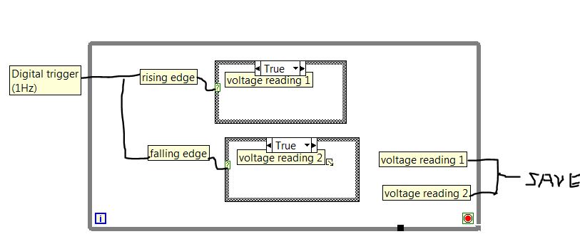
I'm trying to use a digital trigger to collect data on the rising and falling edge. The design is displayed as below. Now, I save the measured voltage 1 & 2 to the local variable in the while loop. Hoever, the while loop runs at a frequency of more compared to the structure of the case triggered. So I had a lot of repetitive data. If I record data directly from structure of the case, it will be recorded as data-0-date-0 because of the ongoing case of fake wire.
I wonder how to revise to save the measured voltage 1 & 2 at the same frequency of up/down edge triggered? Thank you! I have also attached my current version of Labview program, which takes place in time real Labview 2013.
Mcdullna wrote:
Thank you for the answer. Could you be more specific about the use of the shift register?
The case of false just past the value through. With this configuration, you agree that the data remain in the son, avoiding race conditions. It is also more effective than the use of local variables.

-
How to read data from the unit to acquire data with LabVIEW
Hello everyone, I'm new with LabVIEW and I need help. How to build LabVIEW program to read and store the data acquisition unit temperature data. the data can be any store such as Excel or a text file? Thank you.
Start passing by examples of LabVIEW. Go to help-> find examples. There are several examples here just for the analog input and then even more for logging data to a file. After that, show us what you have and we can guide you a little better that way.
-
static/digital waveform output and low frequency measurement of voltage - SMU-6358
Hello
1. I have an attached VI [digital_voltage_output] who must generate a logical true or false static state in the output of the device/port0/line1 Word to say. When the VI works I click the button several times, but nothing happens to the port0/lines1.
2 such a thing [digital_voltage_waveform_output_square] if I'm trying to generate a digital waveform to pin the same with the waveform generating VI. If I connect a waveform chart to the output of the generator function VI, then the chart will show me the good waveform I want, but still nothing is written to the text file.
3. I have read the manual for the X series cards, but it remains unclear for me a little how to things of the road in LV I have a measure of the frequency measurement VI low frequency that I downloaded. It offers me the ports for the supply frequency - ctr0, 1, 2, etc. As far as I'm concerned the PFI ports are responsible for these types of actions. How can I find out the LV that I want to connect say ctr0 and pfi0? »
I use LV 8.6.
Thank you
Kriváň
Hi Kriváň,
The problem you had with the choice of a specific digital line as a physical channel, is that the control that was previously used in this example was created for a data acquisition task that uses a whole port rather than a specific line. I was able to overcome this problem by removing the control and recreate. The control now gives you the option to choose the specific digital lines e.g. port0/PXI1Slot2/$line0.
I was also able to overcome the error of-200802 you mentioned. I was able to do this in a real constant of wiring at the entrance to auto-start the VI DAQmx writing then remove the DAQmx beginning the subsequent code VI. The modified code is attached.
I hope this helps.
Best regards
Christian Hartshorne
NIUK
-
How to control each channel of the signals emitted by the generator of digital waveforms?
Generator has digital waveforms of 8 channels. I need to generate two different signals for HSDIO. How to change and control two different ways? In addition, how to translate pinout of the PXI-6541 to channels? I need pin 1,3,29 and 31 control signal individually.
Thank you!!
You need to combine your personal data in a table. The digital waveforms is simply a numeric representation of the binary table. It always boils down to bit 0 of each element of the array will channel 0 (or the first string that you specify in creating dynamic channels). The next bit goes to the next channel. My last post is very clear. To display the table in binary, right-click on a table element, then select the display Format, then select binary. You can also right click on the element, select Visible, then select Radix Show to display the small b before the number. One last thing, in the display Format window, uncheck the box next to the minimum field width to use. Then set the digital just below zone 8. Then select Pad with zeros to the left in the box below.
You should not use waveforms up to what learn you more about how the HSDIO operates on the input data. It is not difficult to combine waveforms, but it is not as clear as it is using an array of U8, U16 or U32.
Trying to explain further. The first number to be written to the HSDIO will have this effect: Bit 0 (LSB) of the number is written to the first HSDIO string you specify. Bit 7 is on channel 8, you specify. If you specify no 8 channels, the bits download ignored. If wiring in a certain number will produce only a single bit on each channel. In other words, the number has already combines the bits of all channels that you specify. Combine you do nothing yourself. Return to my photo on my last post. By wiring in a table, you cause a binary model must be generated.
I hope that is more clear.
-
Generate analog output waveform finish on request
Hello.
I have a VI that reads in two data channels (400 samples at 400 Hz), calculates the characteristics and classifies data based on a model. If the class is a certain State, a Boolean value called "Détection" is set to True. A second Boolean value called "Stimulation" is also set to true and flip flops and turn off every second up to what the "detection" is more true. Now that I am reading and classify a second data, Boolean values may only be updated once per second. I am wanting to generate output "Stimulation" Boolean is true analog. I had been accomplish this by generating a sinusoidal signal all the time and write to a buffer in a separate loop (500 samples per writing @ 10 kHz) and multiplying by zeros if "Stimulation" was false. I have a code that more or less does what I want, but there is a delay of ~ 200ms between 'Stimulus' is set to True and AO generation, and I feel like it could be simplified. I was wondering if it would be better to generate a waveform finished and trigger to write with the Boolean value of 'Stimulus' (i.e. write 1 second of a sine wave to the changing state rather than write 20 sections of a sine wave in a second, while the Boolean value is True).
Y at - it a good way to do this with daqmx functions? (Generate a waveform of defined duration when a control changes)
-
Update of the segments of waveform by Omega 3000 for the acquisition of personal data
Hi all

I'm having some trouble with segments of waveform of updationg through my acquisition of data personal omega 3000.
The goal is to generate a 1 Hz square wave, which updates of each cycle.
I wanted to avoid generating a new waveform of each cycle, I tried to update.
In the example given by omega, a waveform consisting of 5 segments is generated, and then the third segment (index 2) is updated.
I tried to rebuild so that a single segment is generated and then updated, but I failed miserably.
Configuration of the example VI in this way is not too.
In fact, I'm not even able to set the example VI to update other segments than the third.
I guess that 'Wavelet index' is the right point to set it, but if I put it to sth. other than 2 it just refreshes not anyting.
I can change the five segments of the curve and the update also, but I'm not able to update for nothing, but the second segement.
I hope it's just a simple value to change, but I can not find...
Does anyone have an idea what I might try?
Thank you very much in advance,
Keksbold
PS: I have attached a file so you can see what is the problem:
5 segments: sine, square, triangle, tooth of saw and noise, and for some reason I'm not able to update everything, but the third segment...
Problem solved!
I don't know why, but removing the status of wave DAQIO VI sub set.
I'd be really interested to know why the VI behaves like that anyway, so if anyone has an idea...
(But is more vital
)Thank you all!
Keksbold
-
Generate a digital waveform like memory on PXI cards
Hello
I'm looking for a way to send a large digital waveforms using a PXI digital signal generator. I saw DIO HS cards, but their memory is smaller than the files that I want to transfer. My understanding is that the PXI backplane bandwidth 132 MB/s. So, I shouldn't be able to stream a digital signal from the memory of the card that is slower than the CPU? For example, 50 Mbits / second (equivalent to only 6.25 MB/s)? However, I think I understand after reading their textbooks is that you cannot continuously transmitting a large waveform of the processor memory file, you must transfer the file to the memory of Council first and then transfer that out.
Does anyone know if there is a way to have a flow of digital signal generation card an arbitrarily large directly from memory to the processor of digital signals? Or, what is the fastest card of pxi digital signal generation that does not require the storage of Council first files?
Thank you
Isaac
Hello Isaac,.
Take a look at the following area developer.
NOR-HSDIO Stream from disk (generation) using Win32 file IO
Note that you will not be able to take full advantage of the maximum rate of update HSDIO devices, because the data must be transferred in a bus. Some other considerations are the width of the data as well as the HSDIO device you select, which may depend on other requirements not related to the size of file or waveform (for example the standard voltage or whether you need hardware compare). For more information, take a look at the developer following items area.
Data streaming of Architectures in the PXI systems
The use of National Instruments Logic Analyzer and generator of test patterns SolutionAdvanced features of e/s high-speed digital devices White Paper Series
-
Set the attributes for dynamic data waveform t0 zeros?
HI -.
A beginner to labview here, so please be nice ;-)
I have a simple setup with mainly express screws where I follow the steps below in a while loop
(1) collect signals with the DAQ Assistant, that generates dynamic data. It is the collection of samples of N
(2) changing the attributes of the dynamic data using the express VI 'Set the Dynamic Data attributes'
(3) storing dynamic data revised to a file by using the writing to the file of the measurement.
The problem I was see is that whenever I have insert the express VI 'Set the Dynamic Data attributes' in the data flow, I find myself with a file where synchronization of the signal (i.e., the waveform t0) was cancelled. This seems to happen any dynamic data attributes, I edit. For example, even if I try to set the name of signal I find myself with out having a nulled-out t0
FYI, I'm using Labview 2009 9.0f3, 32-bit
I have attached a code simplified showing what looks like a bug to me. Any help would be appreciated!
It looks like a bug to me as well. Also, unlike other screw Express, you do a right click on it and select open the face before seeing what the problem is. It's pretty simple to find a work around. I converted to a waveform, has obtained the t0 and handed that back as the timestamp for the signal of slected.
-
Module MT FSK. VI, too slow: 5 seconds to generate a single waveform.
Hi guys RF OR,.
I have problems of bigs with the module MT FSK waveform.
I'm trying to generate RF signals, based on sending a stream of input bits to 544 bits with a rate of 8.8 KHz modulation, with a frequency of 15 KHZ deviation and the frequency of 433.92 MHz.
The problem is that it takes 5 seconds, the wave must be generated, that is too long.
I noticed that by changing the rate of modulation (inreasing it) decrease processing time which is normal, but I send with a rate of modulation of 8.8 KHz for my receiver to be able to 'catch' the signal.
Is it possible to decrease the processing time?
Many thanks in advance
Hi all
I found a solution for my problem...
-
Digital output frequency seems to be twice the frequency generated by the basic function generator
Hi Labview forum,
I wrote a program (attached) Labview to generate 3 PWM, square wave, signals that has the same frequency and phase delay right (so that when a signal is off, the other signal is lit. Then the next signal). Everything seems to work fine except that the frequency of the PWM signals generated seems twice as the frequency given to the basic function generator. Anyone have any idea why this is happening? Anyhelp would be greatly appreciated.
Thank you!
Totally agree with the advice of all GerdW than the hardware timing of your hardware DAQ will be much more reliable. That said, part of what you are probably hitting is a little quirk of the primitive delay msec. Requests for 1 msec have long been particularly little reliable (although they * seem * to have improved in recent years, probably due to the better OS support in Win 7 or something).
I did minimal mods to your code with comments from you switch to a timed loop. My quick test showed he is good enough to hit the 1 length of loop of target msec.
-Kevin P
-
How to generate sine waves of the evolution of the frequencies with neither 6733?
I have a card ni6733. I want a specific frequency of the output waveform. After a few cycles, waveform frequency must be changed several times without delay. Bandwidth varies from 0.1 Hz to 10 Hz.
I'm new on the map of NI6733, if have no idea about it. I intend to use the scheme of double buffering for waveform generation. Timing here is critical.
Please give the sequence of function (if possible).
Hi Andrew, I found problem in double buffering when using the buffer of size less than 16384 (32768/2). Why? I don't know... also beyong 1,25,000 "stack overflow" error was coming. Anyway, I dropped the idea of using double buffering. Now I use generation of waveform buffer alone without the help of NIDAQMakeBuffer. Instead, I create the buffer myself having data points of variable frequency to set the number of cycles. as demand for time-duration of profile waveform must be generated is limited to 50 seconds, and I use the rate constant update of 1000 samples per second, buffer size if necessary not creating any problems so far (for now). Thank you very much for your generosity. Rahul
-
I'm doing iPhoto my screen saver and I am not given the choice, when I click on "Source". iPhoto is grayed out. How can I make iPhoto my screen saver? I'll just put up my new iMac.
As a guess I think you need to import your iPhoto library in Photos and chose the photo library.
Maybe you are looking for
-
Toshiba DVD Network Dock II - LAN driver installed but does not
Toshiba DVD Network Dock II PA3007E-1DST I found this file on the internet: "t8103cl9" and I don't remember how I did but I managed to make it work!I needed to reinstall Windows 98 SE on my laptop because I had to, but I have other installation for e
-
Hi, after updating my Ideapad Y480 Win 10 (new installation), my mouse randomly freezes. I would like to browse or just work on my laptop and the mouse would stop responding, the keyboard still works well. And gestures don't work at all - two fingers
-
Hello! So my macbook has acted very strange. I've been on the internet. I was surfing around when suddenly something pops up that says my computer had malware. This kept happening several times. The message says: Attention! Your computer has detected
-
Hello I am a systems and software engineer based in Vancouver. I developed a test system automated using 2013 LabVIEW and TestStand 2013 with custom operator interface.I encountered problem 'lack screw' which is kind of weird because I went to analyz
-
Find the exact index of maximum PNo() local and ChnFind() seem to be problematic
Good day to all experts DIAdem! I am after some help and wonder if what I intend to do is possible, as much as tiara fucntions are concerned. I have a few cyclical data (continuous acquired as a set of data), which I am able to identify individual ev