Transmit power to usrp 2920
Is it possible to adjust the emission of a USRP 2920 power when sending a signal? And if so, how do you do that?
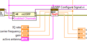
You can adjust the transmission power by changing the slider of the niUSRP Signal.vi to configure in the LabVIEW driver:
If you are looking to make a continuous transmission, the continuous EX Tx example Async.vi niUSRP is a good starting point. This setting adjustable gain from 0 (no gain) 31.5 DB in 0.5 dB steps.
You mentioned that you issue to one USRP to another. Be careful when you do this because it is easy to damage the RF front-end by the introduction of too much power. I would recommend the TX gain setting 0 and adjust the RX gain to avoid damage to your equipment.
Tags: NI Products
Similar Questions
-
Variation in the strength of RF signal using NI USRP 2920
Hello
It is possible to vary the intensity of the signal RF uses USRP 2920? If so, please guide me for this. I would like to transmit the RF signal from 900 MHz with value different GCQ (shows the power of the signal)
Thank you and best regards,
Gowtham Blais
Vindex Hi,
Unfortunately, the USRP is not a device calibrated, you cannot specify an output level of absolute power. However, you can set the gain of the device. The output power varies according to the frequency and bandwidth of the channel that you create, so it is recommended to use a power meter to check the levels of power absolute. The gain is not as guaranteed to be linear. Official warning is formulated as follows:
The USRP devices are not calibrated. The value of the gain does not represent an absolute gain and has no linear behavior. Different devices have different gain for different carrier frequencies curves. You may need to experiment to determine that the right setting for your application of gain.
With this in mind, you can set the gain (in dB) using the niUSRP Signal Configure VI, which is in the palette of the USRP API Tx in LabVIEW.
Kind regards
-
USRP 2920 if after joint bottom (after the MIXING table)?
Salvation _ or
the NI USRP-2920 is a good product I use it to train students on some applications
I read manual for this product its especially usfel and covering a large part of the specs of the device, BUT "nothing mentioned about.
Central frequency (IF).
"to clarify my question" when the signal down mixed RF is it wil be centered arround fixed frequency for demodulation processs "its about 12.5 MHz in one of the device NOT USRP"
What is the center frequency of the baseband signal after mixed down?
I wish I can explain my problem, iam waiting for your answer, answer or tell me you want more explanation on what I want now...
Thank youIt is a direct down conversion device. RF is mixed with the baseband quadrature I and Q. There is not SO.
-
Surveillance of the spectrum with USRP 2920
Hello
I see all the examples on the analysis of the spectrum
but nothing is near my desired app cause
as an example https://decibel.ni.com/content/docs/DOC-40721
It uses an entry 'carrier' and then show spectrum
I want to start and stop frequency within the bandwidth instantenous 2920 USRP
and monitor the spectrum in the band of desierd
I want signals to show their real carriers not baseband signal after demodulation
Thank you
Hello
Can you explain a little more about your use of the application? Frequency range you want to monitor? So, can you explain why you need to "show the signals to their actual carriers and not baseband? The USRP 2920 has only 40 MHz of instantaneous bandwidth (and only 20 MHz with a resolution of 16 bits) so unless the signal of your 'real' sitting in the baseband already (i.e. below 40 MHz) you would be sewing together the spectrum required for an acquisition to wide band and he would not be instantaneous.
Kind regards
John Gentile
Engineering applications
-
can I run labview code written for usrp 2920 on usrp 2940r without change?
If I need to make changes, then what are these changes and how can I do?
Thank you
Hi Joseph,.
I have not seen your code, but it should work without the required changes. You need to change your application to take advantage of the additional channels! Let us know if you encounter any problems.
-
distributed antenna system usrp 2920
Hi all
I implemented an OFDM transceiver using two usrps one transmitter and one receiver, I also did all the normal tasks of synchronization (detection of frame timing recovery, CFO correction and channel estimation) needed to compute the BER to the receiver and it worked very well.
IM now trying to imitate a DAS scenario where I have two transmitters USRP sending the same exact OFDM signal, they are separated by a distance and synchronized in frequency and time using a reference clock. The receiver is a normal OFDM receiver. Thus, the received signal from two transmitters must be seen on the receiver side as the same signal from a transmitter, but with a higher power. Moreover, I need to induce delays of a nano-second between issuers using the trigger of startup time and study the effect on the BER is it possible?
My questions are:
1. it a phase ambiguity between the two transmitters usrp after the use of the reference clock or cable MIMO?
2 - is possible to use the Refin and the PPS and the different trigger time to force specific transmission times?
Thank you
Hey Kareem,
Yes, this should be possible. As long as you use the same reference clock for your USRPs there should be virtually no delay phase. The only delay introduced would be due to the length of wire between USRPs.
Looks like you have two different triggers and they are independently controlled. As long as you do not start the transmission until the USRP receives a trigger, you can specify a delay between transmission by simply delaying one of the triggers of your desired time.
-
Can a single USRP 2920 tansmit (Tx) and receive (Rx) at the same time?
I know a USRP can be a transmitter and a receiver, but a single unit can send and receive at the same time? The application in question involves the sending of an RF signal to a label of RFID and followed by the response of the tag with a single reading USRP. I heard that the link between the channels can cause significant on because bleeding that is not insulation between the tracks, but could not find an example showing simultaneous Tx and Rx. Is there an example or documentation that I'm missing?
Thank you!
Kristen Heck
Academic ESF - middle of Southeast
Hello Kristen,
The USRP can send and receive at the same time. You have because there are bleed more because of the lack of isolation, but documentation of the USRP is always formed and includes no information about this. Here are the 2 screws that allows you to make simultaneous TX/RX. Just to set the IP address in the two screws to the IP address of your USRP and run them. You may need to change the rate of IQ and the frequencies of your application, but this very basic example should be a good starting point.
Let me know if you have any other questions, I'd be happy to help you.
-
USRP. minimum detectable signal 2920?
Hello to everyone! It's only a month since I use the NI USRP 2920.
I have a question pleaseI want to know minimum detectable signal to both ports TX1/RX1 and RX2.
Thank you
Francesco
Hi George, I measure the sensitivity of the USRP...
It's around<-130>
by
-
NI USRP 2940 R safe mode button
Hi all
I have a NI USRP 2940 R, which is unreachble via ethernet (1 Gb) after a firmware change.
To change the firmware, I used the following command:
uhd_image_loader - args = "type = x 300, addr = 192.168.10.2"--fpga-path="/usr/share/uhd/images/usrp_x310_fpga_XG.lvbitx"
The procedure seems to be successful:
-Initialization FPGA... successful loading.
-Image of HG FPGA loading: 100% (areas of 121/121)
-Finalize loading image... successfully.
Turn on the USRP X 310 to use the new image.But after the power cycle, I can not able to ping of the USRP and also orders uhd_find_devices and uhd_usrp_probe say 'No UHD Devices Found'. So I thought I would put my NI USRP 2940 R in safe mode.
In the "GETTING a STARTED GUIDE NI USRP-2940R/2942R/2943R universal software Radio peripheral" (http://www.ni.com/pdf/manuals/375717f.pdf) in the section "why isn't the default Reset IP address?", I found the procedure that says to locate the pushbutton switch (S2).
The problem is that unlike OR USRP 2920 wherein the S2 button is easy to reach, I could not find button SafeMode in NI USRP 2940 a. I have found that the buttons SW1 and SW3.
Anyone has idea about what are the keys SW1 and SW3? Or better, how to reset the USRP NI 2940 R?
Thank you very much for your attention.
Best regards.
Francesco.
Image usrp_x310_fpga_XG.lvbitx implements only 10GbE SFP ports, so you will not be able to communicate with the device via 1GbE, although it is charged. You need probably the image of usrp_x310_fpga_HG.lvbitx which has a single port to 1 GB and the other to 10 GB and is the image that the devices are provided with. See https://files.ettus.com/manual/page_usrp_x3x0.html#x3x0_load_fpga_imgs_fpga_flavours for more information on the different FPGA images available.
There is no safe mode on the USRP AND 2940R, but there are different ways to load a new FPGA image that will work without a functional image already on the device. The PCIe connection on the device may load images temporarily in the device and update the image in flash even if there is no image already on it. USB JTAG connection on the front panel can also be used to temporarily to load a new image so that you can access the device via Ethernet to update the persistent image. Also, you should be able to use the unit normally if you have a connection with the 10GbE. The above linked page includes directions for all of these methods of loading images.
-
Calibration frequency Offset transmitter and receiver with USRP® material
Hello everyone, I read the scripts provided by The Mathworks on the frequency of calibration offset transmitter and receiver with USRP.
The USRP® transmitter sends a sinusoidal signal at 100 Hz with the MATLAB, sdruFrequencyCalibrationTransmitter.mscript, the USRP® receiver. The USRP® receiver monitors the signals, calculates the transceiver frequency shift and displays in the command window MATLAB for calibration with the MATLAB script, sdruFrequencyCalibrationReceiver.m. At the level of the receiver, frequency offset will be calculated and displayed in the command window. The program uses a Spectrum Analyzer to show the spectrum of the received signal. In the program, the corresponding sentense is '% display frequency spectrum. step (hSpectrumAnalyzer, rxSig); "Based on that, I thought that the spectrum analyzer would show the spectrum of the received signal. However, the Web site corresponding site shows "to compensate for a shift in frequency of transmitter/receiver, add frequency offset on the Central frequency of the receiver object SDRu system. Be sure to use the sign of the offset of your addition. Once you have done this, the spectrum displayed by the Analyzer of spectrum of the receiver system object must have its maximum amplitude at about 0 Hz." What I'm confused is, why the Spectrum Analyzer should have its maximum amplitude at about 0 Hz, not other values? Is it because of the characteristics of the USRP itself or the Analyzer of spectrum shows is the value of the difference between the Tx and the Rx after calibration? I use neither-USRP 2920. Your response will be much appreciated! Thank you!
The matlab mfile is found in the following links:
Yes if two devices are not locked to a reference clock, 10 MHz for the USRPs you will see a shift in frequency.
Specifications in ppm, ppb can give you how it can be:
http://digital.NI.com/public.nsf/allkb/2A0B9D3F365DEDEF86256BDB007354EDBye!
-
Hello!!
I'm trying to built a small radar with the USRP 2920...
but I have a problem.
I connect the two ports of the USRP (TX1-RX2) with a cable with low loss of 50 cm...
after transmission of a chirp signal, sometimes I found my IDE oucederomsurlesecondport rx staggered 180 degrees... totally opposite signal
It is possible, it is a problem of the LNA on the USRP?.
Francesco
PS
I had this problem too with the USRP of Ettus 1
The RX and TX share a 10 MHZ reference, but not their respecive derived from local oscillators. This means that the derived LO clocks can lock at different phase shifts that will change every time that the application is executed, but remains at a constant offset (coherent) during the race.
-
conversion to 2921 2920 (and back)
The USRP-2920 contains a 50-2200 MHz Rx/Tx WBX (or similar) daughter card? If Yes, can we this daughter card (temporarily) replace with XCVR2450 of the Ettus, in order to convert the 2920 in a 2921? If so, what other software / hardware (dual band 2.4 and 5 GHz antenna, of course) is required? Thank you for any information you can provide.
Thanks for the quick response. Yes, you're right, test and certification is important. So, this is not a good idea.
-
USRP-1074118634 error code, niUSRP write data Tx (CBD Cluster) .vi < ERR > cannot find a GPSDC
Hello I want to generate a GPS using the USRP-2920 and then plug it into a GPS evaluation kit to verify if the evaluation board can see the satellites, so I run the example
https://decibel.NI.com/content/docs/doc-22178
Everything looks OK, it starts with the legend Buffering Waveform, when it reached 100 I clicked the play button and the program stopped and send this error code:
-1074118634
and source:
niUSRP write data Tx (CBD Cluster) .vi
could not find a GPSDC Could someone help with this?
Thank you
Carlos.
Carlos,
What versions of LabVIEW, NI USRP and GPS Toolbox driver do you use? I noticed the example that you referenced the States ensure to use an external OCXO since the TCXO on the series 292 x is not precise enough. What is happening in RefIn?
-
What is the difference between REFin and PPSin? Can I use the PXI-5652 to synchronize USRPs?
Hello world!
I'm working on a project I want to synchronize 8 USRPs (USRP 2920) as receivers. And it seems that PXI-5652 has a connector REF, so I decide to use it as the reference of the USRPs 8 clock. But I don't know how to connect the PPSin, and in fact I'm confused of the difference between the REFin and PPSin.
Thank you!
Jay_c salvation,
In short,.
REF is the terminal for the device USRP to accept a signal from external reference frequency (10 Mhz).
PPS is the terminal for the device USRP to accept a signal from external time source base clock (1 pulse per second)
You can see this whitepaper for a detailed description of MIMO system about 8 * 8.
Please refer to the section "time and frequency" for information specific to your question.
http://www.NI.com/white-paper/14311/en/
I'm not sure whether you can use the specifically 5652 signal generator for your application.
-
Receive optical power warning - above threshold
As we know,
We cannot set up the optical transmit power of the SFP. However, we can check the power level of reception received by the peer through the command:
View details transceiver interface
However, newspapers have been showing:
20 August 06:45:14.434: % SFF8472-5-THRESHOLD_VIOLATION: item in gi1/0/25: high power warning Rx; Running value:-1.7 dBm, threshold value:-3,0 dBm.
Check:
Optical alarm warn high low warn low alarm
Receive the power threshold threshold threshold threshold
Port (dBm) (dBm) (dBm) (dBm) (dBm)
------- ----------------- ---------- --------- --------- ---------
Gi1/0/25-1 article, 7 + 1.0 - 3, 0 - 19.0 - 23.0This will have a big impact on my switch? In particular the SFP
Factors such as damage, etc.
In addition, how will this affect the performance network, health and functioning of my devices
Your ideas are much appreciated (and if you can back it up with docs, it would be useful also! ^_^)
It seems that your remote line is the sending of a relatively high output power and/or you have a connection very short fiber with very little loss. Since you are only at the beach 'warning', you are not likely to damage any of the SFP receiver or adversely affect the operation of the network. You don't have the possibility to add an Optical Attenuator on the link to make the action more within the specification range.
Maybe you are looking for
-
HP Z820 - BIOS 02.55 rev A - SSD on LSI SAS 2308 do not start... "Non-system disk...". »
Hello MY Z820 workstation is equipped with an Intel 520 240 GB SSD as boot drive, on the integrated LSI SAS 2308 controller. It is a GPT disk. I just tried to update my BIOS Rev 02.08 Z820. at 02.55 a. rev. The update succeeded, and in the BIOS, I ch
-
Equium A60 blue screen after updating XP Home SP2
I have a Toshiba Equium A60-692. I have updated to XP SP2 and now get up a blue screen at startup with the message that ATI driver ati2dvg is entered in a continuous loop. The Microsoft error report says it is because of incompatible drivers, but I h
-
How to find my product UEFI key so I can re - install windows 8
-
stop of using photo black ink to print black text and where is past the color ink?
My HP Photosmart Prem C310 series all-in-one is using the Photo black ink cartridge for printing of text instead of the Black XL that I put in for the printing of the text. How can I use the right to print cartridge? In addition, even if I haven't pr
-
BlackBerry Smartphones suddenly stopped to receive almost all the emails on 8830.
A lot of email this AM, then this afternoon, nothing. Messaging works. Phone works. I can even send a message from my computer to my BB, but nobody else can send messages. Cannot be re-sent service books because I don't remember my password. When