signal of reverse USRP
Hello!!
I'm trying to built a small radar with the USRP 2920...
but I have a problem.
I connect the two ports of the USRP (TX1-RX2) with a cable with low loss of 50 cm...
after transmission of a chirp signal, sometimes I found my IDE oucederomsurlesecondport rx staggered 180 degrees... totally opposite signal
It is possible, it is a problem of the LNA on the USRP?.
Francesco
PS
I had this problem too with the USRP of Ettus 1
The RX and TX share a 10 MHZ reference, but not their respecive derived from local oscillators. This means that the derived LO clocks can lock at different phase shifts that will change every time that the application is executed, but remains at a constant offset (coherent) during the race.
Tags: NI Products
Similar Questions
-
Variation in the strength of RF signal using NI USRP 2920
Hello
It is possible to vary the intensity of the signal RF uses USRP 2920? If so, please guide me for this. I would like to transmit the RF signal from 900 MHz with value different GCQ (shows the power of the signal)
Thank you and best regards,
Gowtham Blais
Vindex Hi,
Unfortunately, the USRP is not a device calibrated, you cannot specify an output level of absolute power. However, you can set the gain of the device. The output power varies according to the frequency and bandwidth of the channel that you create, so it is recommended to use a power meter to check the levels of power absolute. The gain is not as guaranteed to be linear. Official warning is formulated as follows:
The USRP devices are not calibrated. The value of the gain does not represent an absolute gain and has no linear behavior. Different devices have different gain for different carrier frequencies curves. You may need to experiment to determine that the right setting for your application of gain.
With this in mind, you can set the gain (in dB) using the niUSRP Signal Configure VI, which is in the palette of the USRP API Tx in LabVIEW.
Kind regards
-
Hi all
I try to use 2 USRPs of use 1 TX and RX 2 at the same time.
I have connected with cable mimo but Thare is something I don't understand.
When I use the uhd_find_devices command I get--------------------------------------------------
-UHD device 0
--------------------------------------------------
Address of the device:
type: usrp2
addr: 192.168.10.2
name:
series: E6R22NBUP--------------------------------------------------
-UHD device 1
--------------------------------------------------
Address of the device:
type: usrp2
addr: 192.168.10.2
name:
series: E6R22NBUP2 devices with the same address and same publication series.
I use GNUradio, and I can't get any signal in the USRPs (RX) Sources. The files generated by the file sink are just empty (0 Kb).
I'm not sure what I'm doing now.In annex my configuration of the source of the USRP.
Skirpt,
After a few tries, I finally got to use the two USRPs using the MIMO cable.
Thanks for your help
-
configuration of IQ / number of samples for USRP2920
Hello
I tried to save the HF Signal using the USRP 2920. I had an unexpected behavior for certain configurations of IQ rate and number of samples.
When you set the IQ for 1 M as an example and numbers of samples to 60984, the saved file long empty even after recording over a long period of time. It seems that there is an adequate number of sample for a given IQ there is.
Do someone know the trade off between settings of bo?
Thanks for your suggestions
Hi Bolivar,
With regard to the transmission continues in a loop, I think it could help you to make a small piece of transmission over until you actually begin the continuous transmission immediately in a loop. The reasoning being that small initial transmission could help boot to the top of the Tx buffer and prevent cost overruns due the USRP device waiting for data and do not get it.
With regard to the relationship between the right size for a given frequency of IQ, I do not have a precise answer at this stage.
Thanks and good luck.
-
Help urgently needed for the transmission of FM/RDS
I develop a VI to transmit FM/RDS signals using 2920 USRP project last year, and the deadline to submit soon to the VI. I bought the kit FM/RDS, but I'm running into very few problems. I am aware that the FM/RDS Toolbox is designed for RFSG devices, but I'm working on the migration of the screw of the example provided to work on the USRP.
I tried two approaches: the first approach uses the FM/RDS VI tools provided by the box example, and another approach integrates the example VI (only RDS features) with a VI of 'work' to transmit FM signals (takes a file input audio .wav - what is required by my project).
FM transmission:
(1) in the examlpe VI to transmit the signals FM/RDS tools provided by the box, I can not understand how/where at the entrance of my own audio file to the FM transmitter block (instead of the number of FM tones)
(2) where it is not possible to transmit my own audio file using the VI example, how can I integrate the two transmission FM VI I acquired of the forum with the last example VI (outputs have different types: 'Message Signal' vs "niFM SG session")
RDS transmission:
(1) how can I configure RDS block (niFM SG configure RDS groups 2A and 0 b VI) to correctly transmit RDS? --including the frequency of PI and deviation call letters.
Please note that I live outside the United States (in Lebanon) and apparently the IP call letters are designed only for the US?
I've attached a snapshot of the VI where I worked on. It shows how I integrated the example VI and VI of the FM FM/RDS only. Any assistance on all issues is very much appreciated.
Thank you very much!
-
Why the division operator give me different results in different screws?
Hi all
I'm quite the LabVIEW newbie, so please forgive me if it's elementary. I have a signal that I'm acquisition. The signal is fairly low amplitude (.01-0,1 V). During each acquisition, I share the values of the sample defined by another few (0.047) using the division operator. I see inconsistent results and I am puzzled as to why.
In ex1, which I built from scratch for this post, everything works as expected. I can confirm with the debugger that every reading of the sample overall is well divided and the average, max and waveform graph look like I expect.
When I use a similar construction in my real application, however, the division often results in the INF file, and when I look with the debugger I see after fracture of the values of the signal... just don't make sense to me (x 2).
I thought I must be missing something in the real application associated with split and merge multiple signals, so I ripped out everything except the Division (ex3). Although this code looks a lot like the ex1 works well, the product always division infs and strange results.
These three examples receive the same signal. My best guess is at this point that the built-from-scratch example is force double passes to the operator of division "the right way" and that the examples of dysfunction are force double in a different way, incorrect. I tried to delete and re-create the signal path in the examples of dysfunction without result. My problem is that I don't know enough about the LabVIEW data types to find out how to impose the appropriate constraint.
Can someone point me in the right direction for a solution? I would be very happy to help.
Your first image divides your signal of 0.047. Your second and third images are 0.047 dividing your signal. Reverse your son in fracture on image 2 and 3 knots, and I think you should be ok.
-
Acquisition with USRP 2953R of the GPS signal
Hi all
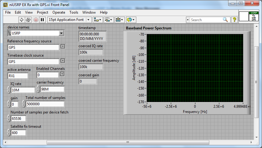
How can I configure a 2953R USRP receive GPS signals? I have an antenna VERT900 connected to the GPS ANT of the USRP port, but in the example VI 'niUSRP EX Rx with GPS', I can't reference this port in the field 'Active antenna'. I put only things like TX/RX or RX1 etc. Should what values I put in other areas as well? I know that the L1 band is 1575,42 MHz.
Hello
The example you posted shows you how to acquire an RF signal on the ports of the USRP with internal clock RF and sources of reference defined in the GPS.
To make it work properly, you must have a GPS antenna connected to the Terminal on the GPS device and installed in a place that receives a good level of GPS signal.
The other control of antenna on the schema defines the port on which to receive the RF signal.
If you want to capture and analyze the signal GPS (RF) itself, you can tune into the front-end RF (carrier frequency) at the right frequency of GPS band and connect your GPS antenna to the RF port.
You can use the simple niUSRP EX Rx continuous Async.vi in this case (but may not work due to the very low consumption of GPS RF signal)
-
Hello world!
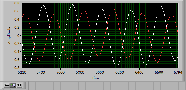
First of all, I use a USRP as a transmitter to emit a sine wave (the signal is exp(j2*pi*f*t)), and then I use the external clock to synchronize the two USRPs (Ref as PPS in are connected to the clock) as receivers. Receivers are in sync, and they are at the same distance from the transmitter, I thought that the signal they receive should have a nearly the same phase. However, in practice, the phase shift is big enough, and this problem really confuses me.
It's the received signals of 2 receivers.
Yes. What you observe is expected.
Near the bottof of this document read the area 'alignment Phase vs Phase coherence '.
http://www.NI.com/white-paper/14311/en/
And also, for the alignment phase, see the following 'Angle of arrival detection with NI USRP '.
https://decibel.NI.com/content/docs/doc-25716
Erik
-
Pxi different 2-5421 or-tclk synchronization help and reversing a signal
I have 2 PXI-5421 function generators. Screened through my vi I load a .hws file and output the same signal makers 2 all in phase and triggering the same point. I need basically to do, it is reverse one signal of 180 degrees and keep them always trigger the same starting point.
im not sure how is invert the signal on a 5421 or how to separate code so that each signal generator is separated.
Hi Liam,
I did a quick search on your issue and I think it is interesting to try to 'configure exit Mode.vi niFgen' (red border on the screenshot) and the value
output mode of entry to the "arbitrary signals" (right click on the parameter "Output Mode"-> create constant-> select 'arbitrary signals' in the drop-down list).
You could include a code of the error you found in your next reply. Thank you!
All the best,
-
Can I use USRP 2 channels at the same time to receive a signal?
Hello world
I want to do an implementation of the time difference of arrival between two receivers (antenna) estimate. I have a kit USRP, Remora and two antennas. There is only one signal source (it is transmitted in nowhere is not serious).
Can I use two channels at the same time the USRP to receive a signal?
I need the original source signal and the delayed signal version.
Thanks a lot for your help.
Sincerely yours.
Uysal.
Hello
I found this post on the forum that can be useful for you. Looks like you can not receive two antennas in the way you describe. I think that this would require a configuration USRP two.
-
How can I use the USRP to record a signal using its two RX ports simultaneously?
Hello.
I am trying to record a signal using two antenna cone. The reason that I need two antenna to cover the bandwidth (DC - 6 GHz). a single antenna covers DC - 300 MHz and the other covers 300 MHz to 6 GHz. so I need to use two RX port of USRP at the same time to record the signal. I have two questions:
1. is this all USRP market capable of covering this frequency range?
2. is it possible to use the two RX port at the same time to the signals of the records I described? If this is not the case, how can do?
P.S. I have two NI2920 USRPs and two USRPs N210 in my lab.
Thanks in advance for your time.
Sam.
Hi Sam,
To answer your first question, the USRPs you can reach the bandwidth you want. There is not a USRP, to my knowledge, that can reach this range in a single device.
Also note that you can only use RX convened for two different ports at the same time using LabVIEW and the pilot of the USRP. If you want to use the two lines of RX, you will need to run a session with a single line, close the session and then start a different session for your second RX line.
-
Hello!
I use a DB9 contact and re232 to communicate with a device, the device needs a five byte long signal in hexadecimal (2 a 00 55 1582). However, when I send the signal by using labVIEW it gets reversed. I ' v tried to the inverse by my selfe but without success. I'm ading a photo on my signal (top) and the right to one (at the bottom) and you can is it should also be high idel. How can I return my signal in LabVIEW?
It really looks like you are comparing apples and oranges. The background signal is not a valid RS-232 signal. The voltage levels are all wrong. If your old device sends this, you'll have to do a translation at the level of the serial port of the pc on the output. There is nothing that can be done in software. The UART of the pc is responsible for the voltage levels and they are correct.
-
USRP. minimum detectable signal 2920?
Hello to everyone! It's only a month since I use the NI USRP 2920.
I have a question pleaseI want to know minimum detectable signal to both ports TX1/RX1 and RX2.
Thank you
Francesco
Hi George, I measure the sensitivity of the USRP...
It's around<-130>
by
-
How to reverse 'Ongoing Acquisition' - Signal (Pike F421B)
Hello everyone,
I am currently working on a machine to control tree cam using the Pike F421B. Before I used the Smartview AVT software. Now my company wants to change for LabVIEW, because we have developed our own analysis program. During the image acquisition process exits camera has "occupied" - signal. My question is: is it possible to invert this signal somehow. I was able to reverse in AVT Smartview but I can't seem to find settings in LabVIEW. This signal is used to trigger LEDs sequentially so that the acquisition of the lighting and the image is synchronized. The problem is the LED controller reacts to the front down a trigger. That's why I need to somehow reverse that signal without external wiring. I currently use the VI "vision acquisition." I would be grateful for any solution. (See also photo).
Thank you.
I assume you mean that the camera came out of this signal by means of a line of input/output, correct? You should probably use some access to the registry to configure this. If you check the manual of your device it should list the records, you must configure and you can then use the registry read/write IMAQdx screws to access.
Another option would be to use an AVT software and save the default settings of this I/O reversal signal in slot voltage by default the camera. Since it is not affected by default IMAQdx framework is broad, it should keep this charged setting even after IMAQdx substitutes parameters with what you saved the VI or MAX Express software.
Eric
-
Hello
I searched for a VI to solve what seems to be a pretty simple (and common) problem but I can't seem to be able to find all messages about this and I spent almost half yesterday on this.
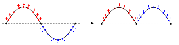
Basically, I would like to convert the wave of negative polarity in positive i.e. to get the absolute amplitude.
Maybe it's better explained visually:
Can someone kindly tell me the good VI which can do the job?
Any help would be greatly appreciated.
Take a look at the building of the "absolute value" in the palette of digital features. It seems to work on the sinewave waveform palette.

Maybe you are looking for
-
problem with the audio walkman NWZ-E463
I have a walkman nwz - e463.the problem is whenever I play any video or audio, songs or video works normally but there is no sound.can anyone help with this. ? the volume control is also absent.
-
H8 1241: problems with the new video card on h8 1241
OK, I've seen a lot of posts on this topic, but I couldn't find anything yet. I bought this computer as a windows 7, but have just upgraded to windows 10. The stock video card HDMI port came out, so I ordered an ASUS Geforce gtx 750ti to replace. htt
-
is it safe to keep the power adapter plugged into laptop all the time?
I was constantly using a laptop Pavilion DV6-1230 we 5 years almost always with the power adapter is plugged in. I replaced the battery once. I was told yesterday that this isn't a good idea, because it can lead to a shorter battery hardware and life
-
Managed to get the WUMC710 running. However, on checking the wireless network settings that they show only 20 mhz despite my setup of router with 80 mhz. The poster also the wrong string. It's all real slow. WUMC710 ASUS RT-AC66U
-
allusion in the spider solitaire - can be disabled
When I try to move cards when playing the lonely spider it now make me click tip to move cards - how to turn off this option