Surveillance of the spectrum with USRP 2920
Hello
I see all the examples on the analysis of the spectrum
but nothing is near my desired app cause
as an example https://decibel.ni.com/content/docs/DOC-40721
It uses an entry 'carrier' and then show spectrum
I want to start and stop frequency within the bandwidth instantenous 2920 USRP
and monitor the spectrum in the band of desierd
I want signals to show their real carriers not baseband signal after demodulation
Thank you
Hello
Can you explain a little more about your use of the application? Frequency range you want to monitor? So, can you explain why you need to "show the signals to their actual carriers and not baseband? The USRP 2920 has only 40 MHz of instantaneous bandwidth (and only 20 MHz with a resolution of 16 bits) so unless the signal of your 'real' sitting in the baseband already (i.e. below 40 MHz) you would be sewing together the spectrum required for an acquisition to wide band and he would not be instantaneous.
Kind regards
John Gentile
Engineering applications
Tags: NI Products
Similar Questions
-
USRP 2920 if after joint bottom (after the MIXING table)?
Salvation _ or
the NI USRP-2920 is a good product I use it to train students on some applications
I read manual for this product its especially usfel and covering a large part of the specs of the device, BUT "nothing mentioned about.
Central frequency (IF).
"to clarify my question" when the signal down mixed RF is it wil be centered arround fixed frequency for demodulation processs "its about 12.5 MHz in one of the device NOT USRP"
What is the center frequency of the baseband signal after mixed down?
I wish I can explain my problem, iam waiting for your answer, answer or tell me you want more explanation on what I want now...
Thank youIt is a direct down conversion device. RF is mixed with the baseband quadrature I and Q. There is not SO.
-
Variation in the strength of RF signal using NI USRP 2920
Hello
It is possible to vary the intensity of the signal RF uses USRP 2920? If so, please guide me for this. I would like to transmit the RF signal from 900 MHz with value different GCQ (shows the power of the signal)
Thank you and best regards,
Gowtham Blais
Vindex Hi,
Unfortunately, the USRP is not a device calibrated, you cannot specify an output level of absolute power. However, you can set the gain of the device. The output power varies according to the frequency and bandwidth of the channel that you create, so it is recommended to use a power meter to check the levels of power absolute. The gain is not as guaranteed to be linear. Official warning is formulated as follows:
The USRP devices are not calibrated. The value of the gain does not represent an absolute gain and has no linear behavior. Different devices have different gain for different carrier frequencies curves. You may need to experiment to determine that the right setting for your application of gain.
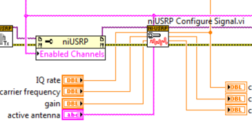
With this in mind, you can set the gain (in dB) using the niUSRP Signal Configure VI, which is in the palette of the USRP API Tx in LabVIEW.
Kind regards
-
Can a single USRP 2920 tansmit (Tx) and receive (Rx) at the same time?
I know a USRP can be a transmitter and a receiver, but a single unit can send and receive at the same time? The application in question involves the sending of an RF signal to a label of RFID and followed by the response of the tag with a single reading USRP. I heard that the link between the channels can cause significant on because bleeding that is not insulation between the tracks, but could not find an example showing simultaneous Tx and Rx. Is there an example or documentation that I'm missing?
Thank you!
Kristen Heck
Academic ESF - middle of Southeast
Hello Kristen,
The USRP can send and receive at the same time. You have because there are bleed more because of the lack of isolation, but documentation of the USRP is always formed and includes no information about this. Here are the 2 screws that allows you to make simultaneous TX/RX. Just to set the IP address in the two screws to the IP address of your USRP and run them. You may need to change the rate of IQ and the frequencies of your application, but this very basic example should be a good starting point.
Let me know if you have any other questions, I'd be happy to help you.
-
bug with the news of the spectrum
Hello
I have a problem with the FRF vi, which calculates the frequency response. The cluster 'info of the spectrum', the channel name is not changed when the FRF vi is looped. It seems that this problem is when the vi Polymorph selection is set to "1 stimulus, 1 reply.
The attached vi shows my problem for a better understanding of the "bug".
The channelname (and perhaps other properties of the spectrum) are not changed. I want to store the result of the FRF vi to a TDMS with polymorphic VI 'Write in TDMS' file available in the Toolbox for sound & Vibration. The Spectra must be registered with all of the properties and the channelname should change...
Someone has an idea to fix this? Maybe I do not use the bandwidth as it should be, but it seems that there is a bug in the vi.
Thanks for your help.
Mathieu
Hello
I found what was wrong in my code.
In order to have the good 'spectrum info', I put the entry "reboot on average" to true on the frequency response of vi.
Mathieu
-
Calibration frequency Offset transmitter and receiver with USRP® material
Hello everyone, I read the scripts provided by The Mathworks on the frequency of calibration offset transmitter and receiver with USRP.
The USRP® transmitter sends a sinusoidal signal at 100 Hz with the MATLAB, sdruFrequencyCalibrationTransmitter.mscript, the USRP® receiver. The USRP® receiver monitors the signals, calculates the transceiver frequency shift and displays in the command window MATLAB for calibration with the MATLAB script, sdruFrequencyCalibrationReceiver.m. At the level of the receiver, frequency offset will be calculated and displayed in the command window. The program uses a Spectrum Analyzer to show the spectrum of the received signal. In the program, the corresponding sentense is '% display frequency spectrum. step (hSpectrumAnalyzer, rxSig); "Based on that, I thought that the spectrum analyzer would show the spectrum of the received signal. However, the Web site corresponding site shows "to compensate for a shift in frequency of transmitter/receiver, add frequency offset on the Central frequency of the receiver object SDRu system. Be sure to use the sign of the offset of your addition. Once you have done this, the spectrum displayed by the Analyzer of spectrum of the receiver system object must have its maximum amplitude at about 0 Hz." What I'm confused is, why the Spectrum Analyzer should have its maximum amplitude at about 0 Hz, not other values? Is it because of the characteristics of the USRP itself or the Analyzer of spectrum shows is the value of the difference between the Tx and the Rx after calibration? I use neither-USRP 2920. Your response will be much appreciated! Thank you!
The matlab mfile is found in the following links:
Yes if two devices are not locked to a reference clock, 10 MHz for the USRPs you will see a shift in frequency.
Specifications in ppm, ppb can give you how it can be:
http://digital.NI.com/public.nsf/allkb/2A0B9D3F365DEDEF86256BDB007354EDBye!
-
The spectrum X 360 screen rotation
Hi, I recently bought the spectrum X 360 with 10 windows, but the rotation of the screen does not work in tent and Tablet mode.
I tried to find a solution for this in the display settings, but this display rotation Lock is enabled and disabled. So I can't even change it.
Please let me know how to activate the screen rotation.
Found a solution: Win + R-> type "regedit" and enter
The Registry Editor opens.
Goto-> HKEY_LOCAL_MACHINE\SOFTWARE\Microsoft\Windows\CurrentVersion\AutoRotation path
Check the value of the file if it is 0 rotation will be OFF, if 1 rotation will be THERE.
Reboot and auto rotation will work.
Note: The lock rotation in display settings button is still disabled, do not know why.
Let me know if it helps.
-
Crackling while playing music in the SPECTRUM of the HP 15-4000 Ultrabook
Crackling while playing music in the SPECTRUM of the HP 15-4000 Ultrabook. TouchSmart with beats audio win 8.1. 64 bit. The problem is gone, when to disconnect the adapter! Update the audio driver is not the problem. any solution?
Hi vinnieee, sorry to hear that you are having sound problems with your computer. I know that the problem you are experiencing is faced with a crackling noise but I'll give you a document that will trouble shoot sound problems. http://support.HP.com/us-en/document/c03257712
I also saw that her you said when the power adapter is disconnected from the judgments of the question. It could be a problem of land, and if that is the question, I would say that contact you HP Total care at 1-800-474-6836 for more in depth troubleshooting. If it is outside your calling area, please click on the link to select HP in your area. http://WWW8.HP.com/us/en/contact-HP/WW-contact-us.html
Thanks in advance
-
can I run labview code written for usrp 2920 on usrp 2940r without change?
If I need to make changes, then what are these changes and how can I do?
Thank you
Hi Joseph,.
I have not seen your code, but it should work without the required changes. You need to change your application to take advantage of the additional channels! Let us know if you encounter any problems.
-
How do you transmit and receive using a single attena with USRP
Hello world
I want to do a reader RFID with USRP. I want to send a signal to activate at the first and then RFID tag receive and decode the signal reflected by the tag. As I know, there are two interface RF on the USRP daughter card, I can send and receive signals using two attenas. But how can I pass the activation signal and receive the signal of the Reflection using an attena?
Thanks in advance
Hi 0711,
If you use the TX/RX port, you should be able to transmit and receive using the same antenna. But it requires more setup code. You should have at least 2 loops in your code - one running a RX session and another execution of a session of TX. You can use the 'End of data?' option on the niUSRP Data.vi of Tx write as a way to send your data without having to start and stop the session every time. In order to obtain the flow of data between the session RX and TX session, I used queues.
I worked to put together an example that illustrates the basic architecture that is required to run an application like this. This example is not polished or finished, but I've seen some requests for how to do this, then I'll post to give you are the point of departure. Please note that this code still has problems that need to be debugged and addressed. It is simply intended to show how to use the end of the data? option to enable transmission shrapnel while receiving data on the same antenna. If you set the TX1 and RX2 antennas use a loopback configuration, you can also use this code with a USRP. Hope this helps and ask questions please.
-
distributed antenna system usrp 2920
Hi all
I implemented an OFDM transceiver using two usrps one transmitter and one receiver, I also did all the normal tasks of synchronization (detection of frame timing recovery, CFO correction and channel estimation) needed to compute the BER to the receiver and it worked very well.
IM now trying to imitate a DAS scenario where I have two transmitters USRP sending the same exact OFDM signal, they are separated by a distance and synchronized in frequency and time using a reference clock. The receiver is a normal OFDM receiver. Thus, the received signal from two transmitters must be seen on the receiver side as the same signal from a transmitter, but with a higher power. Moreover, I need to induce delays of a nano-second between issuers using the trigger of startup time and study the effect on the BER is it possible?
My questions are:
1. it a phase ambiguity between the two transmitters usrp after the use of the reference clock or cable MIMO?
2 - is possible to use the Refin and the PPS and the different trigger time to force specific transmission times?
Thank you
Hey Kareem,
Yes, this should be possible. As long as you use the same reference clock for your USRPs there should be virtually no delay phase. The only delay introduced would be due to the length of wire between USRPs.
Looks like you have two different triggers and they are independently controlled. As long as you do not start the transmission until the USRP receives a trigger, you can specify a delay between transmission by simply delaying one of the triggers of your desired time.
-
Is it possible to adjust the emission of a USRP 2920 power when sending a signal? And if so, how do you do that?
You can adjust the transmission power by changing the slider of the niUSRP Signal.vi to configure in the LabVIEW driver:
If you are looking to make a continuous transmission, the continuous EX Tx example Async.vi niUSRP is a good starting point. This setting adjustable gain from 0 (no gain) 31.5 DB in 0.5 dB steps.
You mentioned that you issue to one USRP to another. Be careful when you do this because it is easy to damage the RF front-end by the introduction of too much power. I would recommend the TX gain setting 0 and adjust the RX gain to avoid damage to your equipment.
-
What gives error of request interrupted on the spectrum screen
Hi all
I want to make a screenshot for ESA series Spectrum Analyzer. I make a screenshot, but still not even the current. If and only if I do not use MMEM
 EL function after reading binary data under vi I screenshot, but not the current one. And if I use the function MMEMEL then I get blank screen capture. And on the screen of the spectrum I always get message that INTERRUPTED the query and error output, I get attention. I don't know what to do these things happened... I'll be very happy if someone help me with this...
Thanks in advance...
Pals
Hi all
The solution that I was using the wait until I changed to the delay of the watch and I sent * OPC? but don't read do not then it was in error.
Thanks for any help...
Pals
-
Hi all
With this code I am defining the spectrum (Center freq, span, RBW, video BW, sweep Time, amp). All the values of what I should automatically not manually set. But when I ran this code, I get no result req. I so want to just know my mistakes...
Thank you very much in advance...
Patricia
Hi all
Its working fine... Just u hv to take care of the orders...
Pals
-
Surveillance using the USB Webcam camera
Normal 0 false false false MicrosoftInternetExplorer4 / * Style Definitions * / table. MsoNormalTable {mso-style-name: "Table Normal" "; mso-knew-rowband-size: 0; mso-knew-colband-size: 0; mso-style - noshow:yes; mso-style-parent:" ";" mso-padding-alt: 0 to 5.4pt 0 to 5.4pt; mso-para-margin: 0; mso-para-margin-bottom: .0001pt; mso-pagination: widow-orphan; do-size: 10.0pt; do-family: "Times New Roman"; mso-ansi-language: #0400; mso-fareast-language: #0400; mso-bidi-language: #0400 ;} "}
A project I want to do is write a Labview application that would communicate to the Webcam USB and publication of the application in a secure web page, and allowing users to control Labview applications at home, work, and anywhere in the world without having installed on the PC of the Labview software. On the web, users can control the Labview front panel for zoom, annotations, etc. As a surveillance camera the USB Webcam will be detect an object moving, save images when motion was detected, an alarm to alert.
I was wondering if anyone can help me with this.
I have Labview Vision and I can get the USB Webcam streaming images.
I don't know where to find information about the detection of a moving object.
Can someone help me on this please?
Hi krispiekream!
I guess that your USB camera has the ability to zoom through a control programmatically? If not you should be able to control the camera using a remote facades, which require the LabVIEW runtime engine. Here's a tutorial on the remote Front Panel LV development of Applications: http://zone.ni.com/devzone/cda/tut/p/id/3277.
With respect to the detection of a moving object, you can take two images and subtract to determine if there was movement in the frame.
I hope this helps!
Kristen H.
Maybe you are looking for
-
Hello, the other day, I bought a GTX 750 TI to replace my 530 GT and when I started my computer, there were beeps sounds and it wouldn't start. I guess there is a problem with my card mother and bios, but I need to clarify if my diet could be a probl
-
Cannot eject DVD after Win7 upgrade on the Satellite L series
I finished the upgrade of windows 7. Everything is going well except that at the end I was unable to eject the windows 7 upgrade DVD. Using the push button above, or right click on the drive and then eject, nothing happens. Can I get a drivers and wh
-
Why l7780 scanner will not work on wifi?
I have Officejet pro L7780 and the printer works fine on a connection Wi - FI, but I can't the scanner to work on a Wi - Fi connection. It works fine on USB key. MBA OS10.9.3,
-
Photosmart C310 prints a half page of word document and stops.
Cannot print any document Word completely. Running OS X Lion on the Mac and Mac Office 2011. Docs stuck in print cue and does not completely print just page. Then there's an error message that the printer is properly - stop I don't it down or off t
-
After several attempts of downloaded installation windows 8, I ended up with a useless and made desktop resettlement using my windows disc 7. Now, the product key for my windows 7 is recognized as a key to upgrade only and does not have to satisfy to