Trigger (acquisition of data for input analog power)
Hello
I want to acquire a signal from a controller of the machine and save the data in a PDM file. In order to develop this application, I created a simulated task. Everything is going well so far, except the start of data acquisition. I want the application to start recording of the data when the signal passes a specific value and stop it when the signal is lower then the value, is obtaining current data which records data only when it is higher then the set limit.
I already tried to use the DAQmx Trigger Vi but I always get the following error message when I use it.
Requested value is not supported for this property value. The value of the property may be invalid because it is in conflict with another property.
Property: Start.TrigType
Requested value: analog edge
Possible values: Digital Edge, no
I also read a lot of different posts on this topic, but I'm still not able to get it going.
I'm pretty new to LabVIEW please excuse if I have a few questions.
A photo and Vi itself is attached.
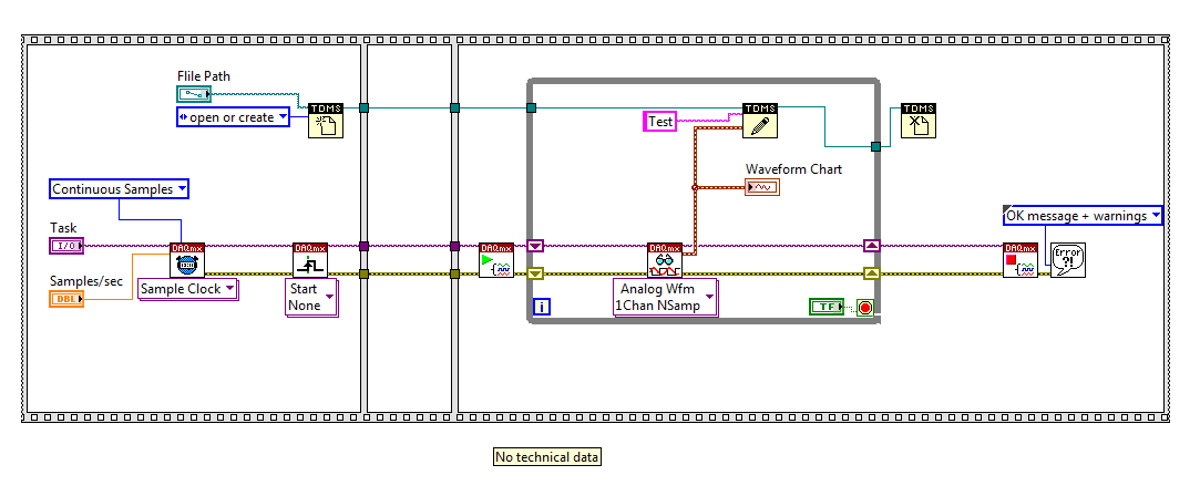
Updated the code has beed saved in LV2014
Tags: NI Software
Similar Questions
-
Components for the Acquisition of data for a Sub miniature sensor
Hello
I'm looking to acquire the data of two simulatneously cells (T4 - 100 L Measurement Specialties ELFS) load Sub miniature. The FS it out 100 lbs to 2.83mv / lb. I already have LabVIEW 8.2 and have acquired data using an analog I / 0 but my signal was weak compared to the noise in the system. I am a high speed data capture because the application that I use has an impact.
My question is: what the amplifier signal conditioner and the DAQ combination would be the best for this aplpication?
Thank you
Scott Kramer
Hi Scott,.
Welcome to the forums EITHER! Looks like you might be interested by the 9237 bridge and strain measurement Module. The 9237 comes in a USB, Ethernet, or Wireless channel, or as a stand-alone module for use with a cDAQ chassis. The 9237 offer a 50ks/s/ch sample rate, up to 10V of internal excitement which should reduce the noise from your system. Based on what you mentioned, it's the product I would recommend - you can find the manuals on the links above to verify that it meets all your needs. There are additional specifications that you need?
-John
-
I am interested in buying a probe voltage signals. I use NIDAQ S-series PCI-6143. My requirement is that I need to acquire only above a certain level. I tried to use the task of triggering NIDAQmx but it fails to give error-200077 code. and the description says im allowed to select only digital edge trigger.
Help, please.
Thanks in advance
HI Maria,
in fact, the message you get is itself, as NI 6143 specifications indicates that this card supports just digital triggering. You will find the list of material of the series that supports analog triggering here: that S-Series (61xx) Support analog devices triggering?, or you can use an external circuit as comparison of analog signal.
Kind regards
s9ali
-
Writing data to extend the acquisition of data for the sampling rate high file
These are the tasks that I have to do to take noise measurements:
(1) take continuous data to USB 6281 Office, in a sample of 500 k (50 k samples at a time) rate.
(2) save data continuously for 3 to 6 hours in any file (any format is OK but I need to save in a series of files rather than the single file). I want to start writing again file after every 2 min.
I enclose my VI and pictures of my setup of the task. I can measure and write data to the file continuously for 15 minutes. After that, I see these errors:
(1) acquisition of equipment can't keep up with the software (something like that, also with a proposal to increase the size of the buffer...)
(2) memory is full.
Please help make my VI effective and correct. I suggest to remove him "write in the action file" loop of consumption because it takes a long time to open and close a file in a loop. You can suggest me to open the file outside the loop and write inside the loop. But I want to save my data in the new file, after every 2 min or some samples. If this can be done efficiently without using Scripture in the measurement file then please let me know.
Thank you in advance.
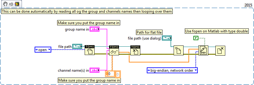
This example here is for a single file and a channel, you should be able to loop over that automatically. The background commentary should be the name of the channel, no group namede the name of the channel in the control.
-
Acquisition of data using the single cycle timed loop in labview fpga (7833R target)
Hi all
I want to acquire data of input analog of a generator using the loop of the timed cycle and DMA FIFO funtion. I want to use the acquired data to act as a process for my PID control variable. Can the attached code perform the goal? I'm skeptical about its features. Advice or suggestions please.
Kind regards
Opuk
The SCTL does nothing for you here. Just remove it and write directly from your analog read the DMA write.
And on the side of the host, you must move the Run method for before the loop.
You should also consider to the PID in the FPGA. PIDs work best in a deterministic environment, and you get more deterministic than on an FPGA.
-
Measurement of low-cost input analog (4-20mA) with data acquisition
Hello
I would like to have a very low cost measurement system loop which I can plug in my laptop current:
I have a load, which is connected to a circuit of air conditioning/signal booster, which output a 4-20mA. I want to measure this current loop signal.
An idea for the lowest cost system? I think that the most NOR DAQ are too expensive and too exaggerated.
I have LabVIEW.
Use of remote sensing current low-value resistance, then measure the fall of voltage through it with the help of an acquisition of data 6008/6009? They have about $150.
You will probably need to amplify current-sense with a MAX4372 or similar resistance to achieve a result that allows you to use a reasonable scale on data acquisition. I measure the current through our products in almost all of our equipment to test in this way. The size of the resistance of meaning as a result. The 6008 is accurate enough, but it is not the fastest nor well presented. But starting at $ 150, they are hard to beat.
-
can you have set for the analog inputs points
If you install an analog input can you get set points that trigger an alarm or an engine that allows you to enable or disable
In SignalExpress you can use alarms to trigger recording on and outside:
Alarms Page - help of LabVIEW SignalExpress
Regarding disabling engines, SignalExpress is not intended to control applications. For controls, you should use LabVIEW or entirely a VI in LabVIEW, SignalExpress. To do the latter, you use a LabVIEW VI step in SignalExpress that will run a LabVIEW VI that performs control of treatment and the output you want. This way you could work in the SignalExpress environment for all the acquisition of data, and you should only use LabVIEW to program control VI (or screws).
-
Use two assistants for the acquisition of data at the same time
Hello
I want to read multiple data channels of analog inputs on my DAQ hardware. However, when I try to create two separate data acquisition assistants for each entry, it gives an error saying "is reserved for the specified resource. The operation could not be performed as indicated "." Can't use two assistants for the acquisition of data at the same time?
I have to add different channels in the same assistant DAQ? I tried, but I couldn't separate the data in different graphs.
How does this work?
Kind regards
Allard
You can't have multiple tasks of the same type (in this case inputs analog) on the same device. Just so having 1 DAQ Assistant read all your channels and separate your channels for individual transformation.
-
We send 5v data acquisition using a voltage generator. Hook us it up to a voltmeter and see 5V. When connect us the generator voltage to a valve "normally open" parker, the voltmeter indicates .14V. It seems that when we connect the two sons of the valve for the voltage generator, the son act as pattern. We want to control the voltage flowing to tap through Labview. We checked the wires to the valve and they work very well, because if we send a constant 5V since the acquisition of data and put ashore, she, the voltmeter indicates 5V. Someone knows why the son act as pattern and low blood to .14V?
nsatpute wrote:
Our data acquisition is NI USB-6259. The valve requires only a 5V max and our DAQ provides up to 5V. However, after connecting the valve to the acquisition of data, the grave tension to almost 0. We start from the principle that the son somehow act as the reason, but we are not sure if this is the case.
The question here is not how much voltage the valve wants, it's the current needs of the valve. The 6259 can put only 5mA via an analog output. Your very likely tap needs much more than that. If you need to add in an amplifier circuit that can supply more current to operate your faucet.
-
Restarting a task for the acquisition of data inside a For loop
Hello
I need iterate through my acquisition of data. Currently, I'm doing this through the creation, implementation and tasks for the acquisition of data inside a loop For which is iterated according to the needs of compensation. Unfortunately, the creation of these DAQ tasks slow down my code.
I would like to be able to create the tasks outside the loop, pass them in and revive the tasks at the beginning of each iteration. Is there an easy way to do this?
Otherwise, is there a way to make the standard DAQmx digital startup trigger trigger several times (so that it starts each pulse data acquisition in a long pulse rather than just the first pulse train)?
Thank you!
-Evan
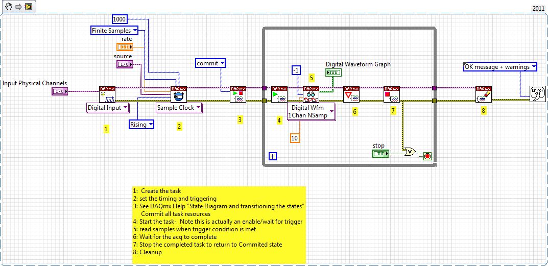
I whent before and created this example for you (and many others.)
-
input analog trigger on the door of the meter to measure the frequency of generation
Hello
I want to measure a frequency on the analog input, but it doesn't seem to work.
I'm trying to work with DAQmx with the use of the ansi c standard.
The first step, I've done was acquiring information on the analog input. With the use of a simulated device, it shows a sine wave on the entry.
My next step is to generate a trigger for the meter signal, but this doesn't seem to work.
I don't see how it is possible to connect the trigger on the entrance to the analog meter.
For the creation of the analog input and relaxation, I use the following code:
DAQmxErrChk (DAQmxCreateTask("",&taskHandle));
DAQmxErrChk (DAQmxCreateAIVoltageChan(taskHandle,"Dev1/ai0","",DAQmx_Val_Cfg_Default,-3.0,3.0,DAQmx_Val_Volts,NULL));
DAQmxErrChk (DAQmxCfgSampClkTiming(taskHandle,"",10000.0,DAQmx_Val_Rising,DAQmx_Val_FiniteSamps,1000));DAQmxErrChk (DAQmxCfgAnlgEdgeStartTrig (taskHandle, "Dev1/ai0 ', DAQmx_Val_RisingSlope, 0 '"));
For the creation of the meter, I use the following code:
DAQmxErrChk (DAQmxCreateCIFreqChan (taskHandle1, "Dev1/ctr1", "", 1 January 2000, DAQmx_Val_Hz, DAQmx_Val_Rising, DAQmx_Val_LowFreq1Ctr, 1, 4, ""
 );)
);)I hope someone could give me a hint.
I also tried the examples that come with DAQmx but well I know this are only examples to counter with the help of the digital inputs.
Thanks in advance.
Hello
You must use the exit event of comparison at the entrance of the meter. Change this property after the configuration string function.
DAQmxSetChanAttribute (taskHandle1, "", DAQmx_CI_Freq_Term, Dev1/AnalogComparisonEvent);
Kind regards
Bottom
-
Input data for digital indicator tab does not exist
Hello
I'm trying to define the range of data for the numerical indicators on LabVIEW 10.0.1. For some reason when I go into the properties of my digital indicator, there is no input data tab as explained on the Web site of NOR: http://zone.ni.com/reference/en-XX/help/371361H-01/lvhowto/changing_data_ranges_of_nu/. In addition, in the tab data type, there is a section for the range, but everything is gray. Any help is appreciated. Thank you
Dig up a very, very old manual (1996!) isn't all that productive. If you want to restrict the output, just use the function in the range and force.
-
Acquisition of data NOR-9205 Assistant set up range of input voltage
How to configure the module NI9205 to use the +/-200mV input range.
I use a custom scale, and it seems that I can not get an accurate reading. I use a shunt current of 100 Ma (max 10A). So I custom balance setting to have 100 x + b. The current flowing in the device is 2 amps and I get a reading of 12-13 amps after custom scale. Now I think the module is configured to sample for the entrance of 10V and I get an error of resolution.
Hi therbert
Since your custom scale is 100 x, to work on the beach of +/-200 mV to your NI 9205 module you must configure your input signal of maximum and minimum range for +/-20 respectively.
According to the equation: Range.max * scale.slope = 200mV * 100 = 20V
This will automatically configure to the scope of the module +/-200 mV to verify you can access the channel DAQmx property node and look for the analog input > General Properties > advanced > Range property, this will let you know in what range is the functioning of the device.
Concerning
-
Looking for a way to mount an acquisition of data USB-6008
Anyone has a suggestion for an acquisition of data USB-6008 mounted on a Panel. I use it for a system where it should not be loose. I have a few ideas, but hope that someone smarter already has a good solution.
Thank you
It is not a robust application, but the box will be moved and I don't want it put in the open air. I simply put a velcro pad on the back and the atttaching in this way. Should be all I need.
-
merger acquisition of data to read input data 2 or several at once
Hi all
I'm using or usb-6009 more then 2 incoming signals.
the problem is that I can't read 2 signals at the same time. 1 my daq assistance will be apeared to be error.
so, how can I set the .vi (attached) so that he could read 1 more signal since the acquisition of data?
I also tried to separate daq support but error. I also try to merge the two signals with a different port (a1 and a0)
can anyone help?
Thnx for the reply
Frankly, I went through all the tutorials and looked for answers in the forum and the conclusions I have difficulties to understand the technical language... I have been looking for everywhere labview users and found someone who could guide me carefully... im have desperately need guidance... not to give up hope trying to find the answer, but a sort of feedback that is giving advice that you need to take the driver's seat... FYI... I take the driver's seat... that look like a real Nubian now needs help...
is there any order step by step so that I could add channels more 1 1 daq help?... I've done it before, but it occurs.
for example, I want to create channel 1 to read the value of the resistance and channel 2 for playback of tension... but what happened when I create more than 2 channels, it is be will configure this channel only 1 located in the block diagram... both channal will give only data for the value of the resistance.
Sorry for my broken English.
Maybe you are looking for
-
Hard drive SSD 80 GB in the Qosmio G50-10 t
Hello Is this hard drive Intel SSD X 25-M 80 GB will work ok as a main system in the Qosmio G50-10 t.
-
Can the Apple Watch warn me when friends are nearby
I thought I read somewhere that if your friend also had a Apple Watch and has been ranked in your friends on your watch, if you're nearby, you may receive an alert. Is this possible? I tried to read how this could be done, but have not found somethi
-
Optimize the image to full screen 2D control
Hi, I'm update programmatically control of 2D image to full screen size. Is there a way to do this? I know that you can maximize the façade to the fulll screen but I have been unable to develop a method which allows me to do that for a 2D image cont
-
White office on the left side bar. Help
Hi, I have a problem with my office, it's a bar of white spot on the left side of my screen and its size is almost half of my office. In this white bar has many options lite my documents, information on archives and etc... Can someone tell me how to
-
How can I reinstall Windows 7 X 64 on my computer dell laptop
HelloI bought an inspiron 15 about a year back pre-installed with Windows7 x 64 Home Premium. While I was away, my younger brother has managed to corrupt my hard drive and must be replaced. Dell people do not provide the DVD of installation as you al