Trigger points - sliders
Hi, can someone help me please about trigger points.
Basically, I create a banner flash/slider. I have 4 images and I want to stop every image playing for 3 seconds and then display the following image. Any ideas? I was watching a tutorial about it but does not have the function code / gave only. I'm new on the thing all code/edge/muse/webdesign and need simple answers right pleeeaaasse front
the video I was watching- http://www.YouTube.com/watch?v=n8XLVLh5MIM
The code given - but does not work...
SYM. Stop();
setTimeout (function () {sym.play(1000) ();}, 5500) ;
Hi Robyn, it is from this work for me.
/////////////////////////////////
SYM. Stop();
setTimeout (function () {sym.play(1000) ()}; 5500);
////////////////////////////////
Is above what you have on each trigger of chronology.
Download sample: http://www.heathrowe.com/edge/slideshow/slideshow.zip
The sample extract: http://www.heathrowe.com/edge/slideshow/slideshow.html
HTH
Darrell
Tags: Edge Animate
Similar Questions
-
I'm trying to convert "a digital trigger point" (an example of data acquisition for the E-series card) for one that runs on the series 621 x, which have similar I/O. No joy. The closest I come is one who clings both labview and my computer, which I am attaching. Any ideas?
Hello
Single-point timed material timing is different from what you will and as the error message is not supported on your map. You are also correct that you cannot use the trigger with a static generation. That being the case, why don't you create a waveform that is several samples of the same voltage and perform a build finished with this waveform. But, you will want to make sure you do not clear this task until everything is done, so it does not reset the card and it's configuration and he hold the last value that was released.
Chris W
-
I believe that a hacker put a trigger point in my BIOS and carries malware on my system
Original title: I had or vhave a pirate in my computor I belrave he \she put a triger point in my bios and my file beleave it is the millwere device how can I check every IIR and bil program builds on
deleting file pirate
Hello
1. what version of Windows is installed on the computer?
2. do you get an error message? If Yes, what is the exact error message?
I suggest you refer to the following article.
How to remove a computer virus?
http://Windows.Microsoft.com/en-us/Windows7/how-do-i-remove-a-computer-virusAlso, please describe the problems you are experiencing more in detail.
I hope this helps.
-
FRM - 40735:KEY - NEXT-trigger POINT raised unhandled exception ORA-20400
Hi am having this error in my KEY-NEXT-ITEM trigger code was developed in 6i get this error when you call another procedure within these proceedings I have exceptionthe form has been improved to 11g, the database is also in 11g
Check how message ora-20400 supprise
Hamid
-
I have 2 (square and sine) signals in the same interval of time, I need to get a trigger point sine wave (I did it with base trigger level VI) and I need now look for the last square base in a wave front of the sinewave trigger point.
Logic as follows:
Index point trigger 1-search in sine wave; (I did it)
2-go back in index until you find the first (or last, so watching from the beginning - index 0) falling edge square wave. How do I?
Figure set
Just use a loop. When the start and end time are the same (i.e. zero), you have reached the end.


-
Trigger two FPGA instances at the same time
I have a basic FPGA code that transmits the bits of data on a serial (RS-485) bus, the code is written so that it expects in the first State of a machine to States in a single-cycle timed loop. After a certain trigger, he begins to read a FIFO containing data and sends the data on a line of Tx. It does this until all bits are send and then it goes back to the first State to wait for the next trigger. The relaxation is necessary because windows must fill out first before the FPGA FIFO can start sending.
I need two instances of this code runs, because I have two buses of com (one is redundant). So I use the FPGA code as a Subvi and I wrote a main FPGA vi to call two separate instances of the Subvi in parallel. A regular window vi wrote on the FIFO for bed FIFO for Rx and Tx. No problems so far.
The thing is I start two transmissions in 200nS of each other (Yes, nanoseconds). Windows will write two FIFO in parallel, but the timing is 4uS apart, too long. I tried implementing a Boolean flag in the Subvi FPGA, but windows can not write directly on the control of Subvi. FPGA won't allow (the Write function is grayed out). I tried to use a FIFO for a flag, but the problem is a race condition. One of the instances is first read FIFO and he destroy. The other can't read. I need a common trigger point to be used by the two instances of Subvi.
My final solution was to use a memory in the Subvi FPGA and digital control in the main FPGA vi. Windows write in numerical order, it may because the control is in the main FPGA vi. Inside the main FPGA, I run a timed loop that looks for digital to be zero. If so, it writes the value into the location of the memory used by the Subvi FPGA. After awhile, the principal wrote a zero back to memory to prevent the Subvi is restarted, as well as to write a zero for digital to reset. This repeats, waiting for windows to write in digital again for the next transmission.
I had to do it this way because sometimes I want to pass on the bus, and sometimes just one or the other. Numeric values are used to determine which to pass on. Now, the transmissions are starting to almost exactly at the same time, 1 or 2 nanoseconds apart. But the trigger process seems very silly to me. I was wondering if there is a better solution. I'm pretty new to FPGA.
tbob wrote:
Basically, I did the same thing using FPGA memory. Windows I am writing for a digital control that resides inside the main FPGA vi. In the main FPGA, I write in the memory. Inside the Subvi FPGA, I read the brief and decode the value to use either one or the other or both buses. After fool with it for awhile, because reading Memeory needs to use a shift register (probably because it takes a whole cycle of clock), I had to work. The two bus trigger at the same time. I guess it's not really important if I use a FIFO or if I use the memory. The main problem is that I write Windows at the hand of FPGA, then the hand of FPGA for the Subvi FPGA. Then the time is right for what is the Subvi is.
There are some advantages to the use of two FIFO on your approach. First of all, you don't have the change of register for the memory location. Secondly, we should not worry that VI is responsible for compensation to the memory location, or do, you run the risk that one of your subVIs run twice, or not at all, if the memory is not erased at the right time. Perhaps most important, you'll save yourself space on the FPGA because you will not need arbitration - the additional code that is added when two parts of the FPGA try to access the same resource at the same time. In your case, both instances of the Subvi access the memory block at the same time, so the FPGA compiler adds additional logic to avoid conflict. If only read you the memory block in one place and just write it in one place (reading and writing can be different loops where subVIs) there is no need for arbitration. Using two FIFOs, you can keep independent and avoid the conflict resolution code. See the help for the "arbitration" for more details.
-
I tried to do previously in AS2, hacked using 2 text boxes different and visibility, eventually give up in frustration.
I am trying to build the same in AS3, and I think that I should implement such a feature, and there must be a way to do this.
I have therefore a component TextArea that I use to display video cue points. I want every new cue point to fade out of the trigger point, to help the user stay focused on the video. I did a bunch of research on Google and looked through aid, without result. Now, I ask the community. Does anyone know of a way I could do?Sorry its so long that I posted back, I'm overwhelmed and later was able to return to this problem.
I ended up pulling BitmapData of the background image on the fly, which fell on top of the newly added text and it fading. It works quite simple, as shown in the code below.
First of all, I put the textHeight of the field to a variable.
Then, I added the text of landmark.
Then, I grabbed the new textHeight and calculated the difference.
Then, I checked to see if I was scrolling. If so, define the scrollPosition at max and restore the height from start until the bottom of the box less the difference in heights.
Then I instantiate my BitmapData and draw the background to her image.
I then draw it to a Bitmap object and scrollRect to the Bitmap based on the height of beginning and the difference in the value.
Finally, I start a Tween to disappear the Bitmap image.My code is not the most optimized world, as I do the optimization, once the entire project is nearing completion.
-
Hello
I'm new to forms, form related to oracle apps.
When I open the form and query(CTRL+F11) form after getting the records, when I close the form without making any changes is to show that 'DO U WANT TO SAVE CHANGE', in general it should not.
If I comment the code in 'Post-QUERY' form works very well.
but I have to retrieve data in a post REQUEST.
Please help solve
Thanks in advance
Comer.The problem with reading the additional elements in the post trigger often, is that you have a sort of 'cross-validation '. In this case, if the articles you read in PQ itself have a WHEN-VALIDATE-trigger POINT on it which then alter some elements of database again... If you fill in the elements of PQ the WHEN-VALIDATE-POINT-trigger fires.
The best way to avoid this is affecting the reocrd any query registered at the end of the POST-QUERY-trigger:... SET_RECORD_PROPERTY(:SYSTEM.TRIGGER_RECORD, :SYSTEM.TRIGGER_BLOCK, STATUS,QUERY_STATUS); -
Cable modem of CM600 default after large downloads
Hi-
I use a CM600 modem with a router WNDR-3700v4.
Recently, the cable modem has started to behave very strangely after the download of large files (1 GB or more seem to be the trigger point). Once the download is complete, I started experiencing excessive latency and packet loss to external sites. Ping times jump around 20ms for 3000ms and package loss ranges from 0% to more than 50%. Restart the modem cable does not resolve the issue until I download another file of large size. Interestingly, I found that if I disconnect the cable modem LAN cable when it is defective, the modem still shows an activity and a LAN link on it. I expect the activity ceases when he is physically disconnected and link drop. I swapped the ethernet cable and it made no difference.
If anyone of you thin people have ideas?
Thank you very much!
The modem has been replaced and the problem disappeared. Yay guaranteed.
-
Rotary decoder in real-time and 'pulse shifter '.
Hello world
I'm putting in place a rotating decoder for use as a shifter of pulsation by labview real-time.
Basically, this means I have two input channels (ttl-legumes, ~ high 20us) rotary engine. A channel contains a pulse at each CA (angle cranc) ° up to 12 kHz (increment). The other channel contains a pulse every 720 ° CA (the charge cycle, BDC_cc low break-even point). With this information a pulse to be generated on an output also channel ttl (high), which triggers my setup of measurement. This impulse must be moved in a programmable relationship to the entrance of BDC_cc, which aims at a table of regular measure.
I got it running by streaming the channel of BDC_cc until a rising edge is detected, then count the edges of increment to the designated trigger point and then generate a pulse on the output channel. The problem is that the late 70-120us exit trigger. In short it's too; a maximum error of ~ 20 is acceptable. Digital channels appear to work faster, so I put discarded Counter-based acquisition.
I'm quite new to LabView, so I'm sorry if the answer is obvious...
My purchase setup consists of:
PCI-MIO-16-1
BNC-2120
LabView 12.0
Max 5.3.1f0Widows XP
This configuration seems to exclude some options Labview offer, such as the external digital acquisition sampled or externally triggered by the acquisition in the base. A manual interpretation of analog inputs is way to slow.
I have attached my working version.
Any input appreciated woud...
John,
I only have a minute right now, but think I can play with a device simulated tonight or tomorrow.
I'm quite sure that there would be a clean solution clocked by material if you use a series M or X-series
Council MIO, but the older generation counters timers on the set of the E series do support everything which
You need. It's been a while since I had to rely on this generation of hardware.
I think the basic approach is to use the lunatics of angle as the clock pulse train that defines the
delay time of the pulse you want to generate. You could be "Timer" the pulse based on the real
angular position, helping you synchronize to a specific angle of crank. The question is whether and how E-series
counters of takes to support the generation of pulses triggered (or redeclenchables). If they are not, I would say that you consider
get new hardware DAQ which support this kind of trigger and you give a very precise pulse
implementation.
-Kevin P
-
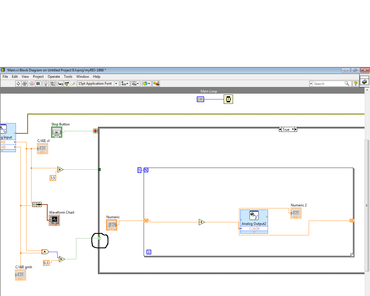
Case held (not gel) for some time
So I got 2 analog input via NiMyrio and I got a deal of true/false because if the two signals larger than the trigger point as I put, it will enter in the case of true.
The problem because both signals is put in correspondence with the comparison to very fast time, this means that the real case will happen after this date that is too fast. After that it will change to cuz case misstep signals of time corresponding to the comparison more.
If the case don't give me enough time to fulfill the function inside the housing. (example I want number 5 decremented to number 1 in 5 sec but it could not be done because of the case will turn to false cases like the true case happening very quickly)
There is nothing to do with signals, their charesteristics who behave so
I wonder is anyway I can hold the case for time to complete the function inside as the true case happening too quickly according to the signal.
"I tried" delay "and" wait until the next multiple. They can hold, but at the same time to freeze the program as well which is meaningless cuz she also only freeze function inside I want to perform.
IN summary, I want to keep (no gel) the true case and don't function inside at the time of the operation, as described in the pictures
Thanks for your help
Here's what happens:
-Once the case is entered, the delay time say you keep of 100ms
-If the remaining part of the code runs at scenario1:50ms and scenario2: 150ms
-In scenario 1: because of the delay, the case held for 100 ms-50ms = 50ms
-In scenario 2, the code moves after completing its code.
-Until the delay time provides is the case will take minimum of 100 ms.
-Timer is just pointer to the clock and during this time also code runs.
-
floating signal with a time dependent thresholding
Hi all
I have a floating signals that need a time threshold function. For example, if the signal to pass more than 0.2 V in less than a second then an alarm is set otherwise the base line and if the signal from 0, 2V in more than one second and then alarm stays off and vertical offset. I tried different techniques such as the spreading of the signal and deducting his originals, but nothing seems to work I also tried to set a delay time, but all of the channel of the instrument are then delayed even if created in a Subvi. could someone help me please?
Thanks in advance
Frédéric.
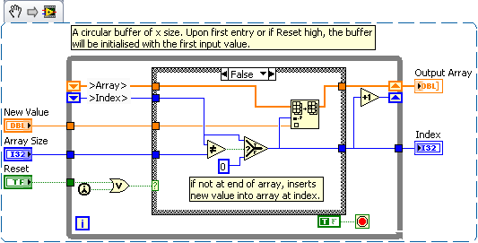
Hi Fred,.
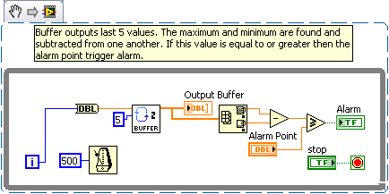
I have re-written the buffer circular for you and also written a small code demo showing how to find the max and min and an alarm is that is greater than or equal to a trigger point:
Circular buffer 2, this time I do not turn the buffer but just increment an index and clock this more when the buffer is full.
Here is a small demo vi showing how to raise an alarm if the difference of the maximum and minimum value is equal to or greater, then a trigger point.
With regard to the circular buffer 2 I pulled out the current index value. This is where you need to go through the buffer sometime running during the first to the last command. You can use this value to index as your starting point.
I hope this helps.
RGS,
Lucither
-
Hey everybody,
I have a particular problem regarding the logging of data after a certain trigger condition has been met.
My task is to save some data based on a particular trigger condition, data to be connected must be previous data (e.g. 1 sec prior) and the entire procedure (for example, 1 second after) the trigger point.
So far, I scoured the forums and my current VI is based on the solution listed here: http://forums.ni.com/t5/LabVIEW/Log-data-before-and-after-occurance-of-a-Trigger-Condition/m-p/32095...
The solution above uses the 'tail' function, and I'm not sure if I am using it correctly.
My problem is that I can indeed save data when the trigger is reached, but I'm not sure how to continue this record for a certain period of time (e.g. 1 second) after the occurrence of the trigger.
I would be very grateful if someone could provide assistance. I have provided a copy of my VI developed as a reference

Just better to avoid the evil dynamic data in LabVIEW!
Here I show you one possible way to save the three data blocks. Note that this solution could create overlapping when it follows the trigger conditions appear. But you can improve the example more far. I also created a Subvi for backup, more space this way (Save_data.vi) of the data...
Subvi:
Loop of consumer:
-
I would like to change when a player is red because when it is close to being complete.
I have a 2 TB drive that displays red whith 120 GB free. I would change the trigger point to turn the Red disc.
Thank you
Darrell
"dpelan" wrote in message News: 3e567137-4 d 21-4443-b457-70b8177f41a8...Thank you! Both drives are given only (Y: X :). Is it possible to change the alert?
Not really--or safe.The alert works in point 15% because in this region, Defrag becomes unreliable and is therefore disabled. If you activate the alarm turned off, then defrag may also be allowed to continue to run in the background, and it can damage files.
--Noel Paton | Nil Carborundum Illegitemi | CrashFixPC | The lazy three fingers
-
Nice day
I recently updated a Windows 7 Home Premium 64-bit for Windows 7 Ultimate 32 bit. Long story why, but it works better since.
There is one thing that past seems weird. CMD (I think that's it), or this black screen command prompt appears on the screen every now and then. I can't tell what is the boss, or that it triggers. But it is quite often.
What this has to do with being administrator or the administrator account on my own laptop. Nobody else uses it. This is my personal laptop. I log into my admin account when using the laptop and do not use the other account username or guest account. This is info I added here for your info.
The blinking indicates something wrong? Or how I disable that or stop its frequency?
Thank you very much!!
Massachusetts
And how can I stop the task?
I will also say that the screen flashes about 8 times in one hour.
Before you can stop the task, you must identify it. You can do the following:
- Launch the Task Scheduler with the taskschd.msccommand.
- Click the task Scheduler Library.
- Consider different trigger points.


Maybe you are looking for
-
T2 "ContentService stopped suddenly.
I get the error message: "the ContentService application has stopped unexpectedly. Please try again. "This happens everytime I turn on my PRS - T2 once it has been completely closed. I tried a soft reset and the same thing is happening: after pressin
-
MechWarrior 4 Vengeance installed but freezes immediately
I reinstalled an old copy of MW4 revenge (on a new computer with Windows Vista), and whenever I open it, it freezes immediately. To do anything, I have to go to Task Manager and he tells me that MW4 is "not responding". I tried as an administrator,
-
How can I watch live TV on my computer?
I want to watch TV on my computer! I have a plug-and-play monitor to 800 x 600 pixels.
-
must my computer be connected to the internet for the development of work?
must my computer be connected to the internet for the development of work?
-
How do I know what motherboard is installed
I have a HP h8 - 1070t. How do I know what motherboard is installed? Should I update my BIOS I install more memory?