a digital trigger point
I'm trying to convert "a digital trigger point" (an example of data acquisition for the E-series card) for one that runs on the series 621 x, which have similar I/O. No joy. The closest I come is one who clings both labview and my computer, which I am attaching. Any ideas?
Hello
Single-point timed material timing is different from what you will and as the error message is not supported on your map. You are also correct that you cannot use the trigger with a static generation. That being the case, why don't you create a waveform that is several samples of the same voltage and perform a build finished with this waveform. But, you will want to make sure you do not clear this task until everything is done, so it does not reset the card and it's configuration and he hold the last value that was released.
Chris W
Tags: NI Hardware
Similar Questions
-
Hi, can someone help me please about trigger points.
Basically, I create a banner flash/slider. I have 4 images and I want to stop every image playing for 3 seconds and then display the following image. Any ideas? I was watching a tutorial about it but does not have the function code / gave only. I'm new on the thing all code/edge/muse/webdesign and need simple answers right pleeeaaasse front
the video I was watching- http://www.YouTube.com/watch?v=n8XLVLh5MIM
The code given - but does not work...
SYM. Stop();
setTimeout (function () {sym.play(1000) ();}, 5500) ;
Hi Robyn, it is from this work for me.
/////////////////////////////////
SYM. Stop();
setTimeout (function () {sym.play(1000) ()}; 5500);
////////////////////////////////
Is above what you have on each trigger of chronology.
Download sample: http://www.heathrowe.com/edge/slideshow/slideshow.zip
The sample extract: http://www.heathrowe.com/edge/slideshow/slideshow.html
HTH
Darrell
-
USB6259 static with digital trigger
Hello
I have a VI that controls a control of linear motor with digital lines. At one point in the program setting one of these pipes triggers a task of analog input and a task of Pulse counter. This is done by putting a wire between the digital line and for example. PFI0 use this as a the input trigger. This works well.
My general question: is it a solution, where I can use an internal signal of the 6259 avoiding the connection of the wire?
Matthias
Hi mq17,
I have found no clear information, saying that it is possible (or impossible). What you should try is to create an internal route between the digital line and PFI0 using the DAQmx connect Terminal VI. I can't guarantee this will work, but it's worth trying:
DAQmx connect terminals (VI)
http://zone.NI.com/reference/en-XX/help/370469AA-01/lvdaqmx/mxconnectterminals/
Don't forget to unplug the terminals at the end of your program
Best regards
-
I believe that a hacker put a trigger point in my BIOS and carries malware on my system
Original title: I had or vhave a pirate in my computor I belrave he \she put a triger point in my bios and my file beleave it is the millwere device how can I check every IIR and bil program builds on
deleting file pirate
Hello
1. what version of Windows is installed on the computer?
2. do you get an error message? If Yes, what is the exact error message?
I suggest you refer to the following article.
How to remove a computer virus?
http://Windows.Microsoft.com/en-us/Windows7/how-do-i-remove-a-computer-virusAlso, please describe the problems you are experiencing more in detail.
I hope this helps.
-
FRM - 40735:KEY - NEXT-trigger POINT raised unhandled exception ORA-20400
Hi am having this error in my KEY-NEXT-ITEM trigger code was developed in 6i get this error when you call another procedure within these proceedings I have exceptionthe form has been improved to 11g, the database is also in 11g
Check how message ora-20400 supprise
Hamid
-
Hello friends,
I have a question. I need to trigger an output of Myrio with a single pulse. After the pulse, the output will remain active. Then with another single pulse, the output will be switched off. Should what tool I use?
Thanks for listening,
Kind regards
David
Hi Davi08,
I did a little research for you answer and I found another "NI Discussion forums" forum that maybe can help you.
Try using this link, I think this will help you.http://forums.NI.com/T5/academic-hardware-products-Elvis/myRIO-digital-trigger/TD-p/3278560
Best regards
-
the analog inputs with digital edge trigger
I am currently triggering a readout with a digital trigger using a 0 - 5v as the digital source encoder. I am running LV 8.2.1 DAQmx 9.0 and a PCI-6259. I use a VI I wrote and which is very similar to 'Acq & chart voltage-Ext Clk.vi', and using the one-pulse encoder connected to PFI8 as the clock source for the sample clock vi. The only major difference is using the channel of the Z-trigger as a software reset inside the While loop with the DAQmx reading. Currently, the sample clock doesn't allow that either read the lower edge or an increase of PFI8, so I get a sample by one-pulse.
I need to double the rate of analog playback for a given tree rpm and encode them, so I need to read on the fronts and edges of the one-pulse encoder. The sample clock can be reconfigured for the detection of changes and still read the PFI8 port to increase and decrease as inputs of physical channel, or do I have to configure detection of modification of the task/digital input for a single line and use the "ChangeDetectionEvent" as the source for the sample clock HAVE? Detection of Timing/change DAQmx can still use the signal in PFI8, or should I use DI ports, and which ports are DI should I use?
Thanks in advance!
In fact P0.8 is. I was looking at the pinout for the 6251, no 6259. Sorry about that.
-
analog output digital start trigger the api c
Hi, I'm trying to start analogue output based on a digital trigger (either PFIO or a PXI line) I can make this easy in LabVIEW. However with the C API (through the Python wrappers), the problem is when I call DAQmxBaseWriteAnalogF64, writing will always be timeout that the acquisition was not triggered. However, I can't call it after the trigger occurs, because obviously, it will be too late.
I can't find any examples of C API where the analog output is triggered a digital triggering. I can find for the analog input, but is fundamentally different that you can CONV read anytime after the trigger occurs.
Python code as follows (functions are equivalent ot C API, even if you have no need of ot pass the task handle such that it maintained as part of the Task object)
# create analog output task
analog_output = Task()
analog_output.CreateAOVoltageChan("Dev1/ao0","",-10.0,10.0, DAQmx_Val_Volts, None)
analog_output.CfgSampClkTiming("",outputRate, DAQmx_Val_Rising, DAQmx_Val_FiniteSamps, numSamples)
analog_output.CfgDigEdgeStartTrig("/Dev1/PFI0", DAQmx_Val_Rising)
analog_output.StartTask()
analog_output.WriteAnalogF64(numSampsPerChan=numSamples, autoStart=False,timeout=1.0, dataLayout=DAQmx_Val_GroupByChannel, writeArray=data, reserved=None, sampsPerChanWritten=byref(samplesWritten))print("Analog output: Wrote %d samples" % samplesWritten.value)# create digital trigger dig_out = Task()dig_out.CreateDOChan("Dev1/port0", "", DAQmx_Val_ChanForAllLines)

# create digital trigger function
highSamples = 1000
numpts = 3 * highSamples
doData = np.zeros((numpts,), dtype=np.uint32)
doData[highSamples:2*highSamples] =  2**32 - 1

# send digital trigger
doSamplesWritten = c_int32()
dig_out.WriteDigitalU32(numSampsPerChan=numpts, autoStart=True, timeout=1.0, dataLayout=DAQmx_Val_GroupByChannel, writeArray=doData, reserved=None, sampsPerChanWritten=byref(doSamplesWritten))
print("Digital output: Wrote %d samples" % doSamplesWritten.value)
Hi PatrickR,
You can review examples of code NI-DAQmx (ANSI C) text based on the production of an output using a trigger to start digital analog. If you included/checked support textual dusing your NI DAQmx driver installation, you can navigate to Windows start > all programs > National Instruments > NI DAQ > Teaxt-Based Code support > ANSI C examples > analog output > generate voltage > Mult Volt updates-Int Clk - Dig start. If you have questions/doubts about the material.
-
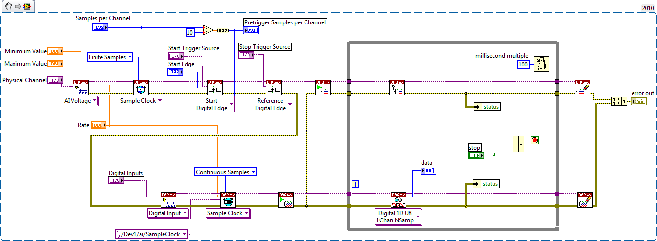
DAQmx: set up a digital acquisition continues with start and stop trigger
Hi all
I write because I can not find a solution to my problem.
As written in the title, I just want to do an continuous (continuous sampling) a digital line. The fact that it's a digital line instead of an analog is no big deal, I guess. I want to start the acquisition on a rising edge of digital trigger (PFI0 for example) and stop acquisition on a trigger too (forehead down on the same signal (PFI0 even then) or a new front amount). This way I could precisely control the time of acquisition or of the start or stop other devices.
Since this is a digital acquisition, you need to do first "something": create a fictitious analog input task and get the clock back to the digital input. I setting this analogue of the task to start on a trigger. It works but I can't find a way to stop it on another trigger.
Do u hav no idea how to implement it?
Finally I have not found an easy way to break cautiously the VI to wait for a trigger (in case you want to start an acquisition with different settings for example). Do you use the task to Abort or is it better to set a deadline to playback digital channel VI until the outbreak occurs?
Any help would be appreciated!
Thank you
Config: LV 2010, latest version Daqmx and USB card or 6251.
Hi Chris,
One way is to use counters as Kevin described. For me, it's usually easier to create the dummy task that has the timing engine (as I HAVE), but it depends on what resource you have on your board you will not need
 .
.In fact, the example is the same thing that you need to measure continues - just what you need to do is remove the counter part and replace the trigger reference to be external (your stop trigger).
with this approach, you should be able to do the continuous measurement - I noticed that you need DI - in fact with few changes you should be able to use this example. DI does not have its own timing engine, that's why you should use the external sample clock. If we use the example to create dummy HAVE to provide the sample clock, and we start DI task until we start to HAVE fake, then we can get pretty much continuous clock which begins start trigger and stop the trigger of reference.
Take a look in the change - once again, I have not tested, but logic seems to be OK.
with sincere friendships.
s9ali
-
Dear community,
I am trying to implement a background basket (software) PXI trigger on a chassis NI SMU-1082 with LabView 2015 (32-bit) running on an SMU-8135:
HS-DIO (SMU-6544) in slot 2,
-Acquisition of data (SMU-6363) into the Groove 4,
-Flex RIO (SMU-7962R + OR-6583) in the Groove 3.
The trigger schema is explained in the attached file ' LV-PXItrig-HSDIO-DAQ - overview.jpg ".
Scenario 1: written DAQ analog signal and sends signals trigger HS-DIO (software) through bottom of basket, after East of waveform of the complete signals to DAQ for acquisition.
Scenario 2: logical impulse on an external port HS-DIO triggers signals HS-DIO, after HS-DIO waveform is complete DAQ triggered for the acquisition of the ADC by the backplane.
In principle this breaks down to send a trigger of module A to B by PXI backplane. The SMU-1082 chassis has a bus trip with 8 lines (PXI_trigX, X = 0,..., 7) more a trigger in Star controlled the slot 2.
I've linked to implement a software trigger, but I can't access the refreshing resource and execution, see the attachment. Other ways of implementation including the DAQmx Terminal / routine disconnect Terminal have not worked for me either. I am aware about the connection of trigger using the node property VISA but I can't make a trigger.
Tips, comments or solutions are appreciated. Thank you!
For scenario 1, you want to trigger the HSDIO acquisition to begin as soon as the analog output DAQ starts? You can use
DAQmx Export Signalto send the trigger for the start of one of the lines from the Trig PXI backplane. Then, you need to configure your HSDIO acquisition to use a trigger digital beginning on the same line of trigger. Take a look at the example of the "Dynamic hardware generation start trigger" in the Finder of the example (help > find examples)For scenario 2, looks like you do a dynamic unit HSDIO generation when a digital trigger arrives on one of the PFI lines. Once the build is complete, you want to send a trigger for the DAQ hardware to begin sampling. If this is the case, you again use a trigger to start material in your task of NOR-HSDIO, as you did for scenario 1, but use external trig line as the source, rather than the bottom of basket. There is no case of material when the build is finished, but you can use a marker in script mode event instead. The example of the Generation with dynamic event marker' in the example Finder gives a good starting point for this type of operation. You'll want to set the output terminal for the event to be a line of backplane trig, and then tap the DAQmx to start on the same line trig trigger.
-
Trigger two FPGA instances at the same time
I have a basic FPGA code that transmits the bits of data on a serial (RS-485) bus, the code is written so that it expects in the first State of a machine to States in a single-cycle timed loop. After a certain trigger, he begins to read a FIFO containing data and sends the data on a line of Tx. It does this until all bits are send and then it goes back to the first State to wait for the next trigger. The relaxation is necessary because windows must fill out first before the FPGA FIFO can start sending.
I need two instances of this code runs, because I have two buses of com (one is redundant). So I use the FPGA code as a Subvi and I wrote a main FPGA vi to call two separate instances of the Subvi in parallel. A regular window vi wrote on the FIFO for bed FIFO for Rx and Tx. No problems so far.
The thing is I start two transmissions in 200nS of each other (Yes, nanoseconds). Windows will write two FIFO in parallel, but the timing is 4uS apart, too long. I tried implementing a Boolean flag in the Subvi FPGA, but windows can not write directly on the control of Subvi. FPGA won't allow (the Write function is grayed out). I tried to use a FIFO for a flag, but the problem is a race condition. One of the instances is first read FIFO and he destroy. The other can't read. I need a common trigger point to be used by the two instances of Subvi.
My final solution was to use a memory in the Subvi FPGA and digital control in the main FPGA vi. Windows write in numerical order, it may because the control is in the main FPGA vi. Inside the main FPGA, I run a timed loop that looks for digital to be zero. If so, it writes the value into the location of the memory used by the Subvi FPGA. After awhile, the principal wrote a zero back to memory to prevent the Subvi is restarted, as well as to write a zero for digital to reset. This repeats, waiting for windows to write in digital again for the next transmission.
I had to do it this way because sometimes I want to pass on the bus, and sometimes just one or the other. Numeric values are used to determine which to pass on. Now, the transmissions are starting to almost exactly at the same time, 1 or 2 nanoseconds apart. But the trigger process seems very silly to me. I was wondering if there is a better solution. I'm pretty new to FPGA.
tbob wrote:
Basically, I did the same thing using FPGA memory. Windows I am writing for a digital control that resides inside the main FPGA vi. In the main FPGA, I write in the memory. Inside the Subvi FPGA, I read the brief and decode the value to use either one or the other or both buses. After fool with it for awhile, because reading Memeory needs to use a shift register (probably because it takes a whole cycle of clock), I had to work. The two bus trigger at the same time. I guess it's not really important if I use a FIFO or if I use the memory. The main problem is that I write Windows at the hand of FPGA, then the hand of FPGA for the Subvi FPGA. Then the time is right for what is the Subvi is.
There are some advantages to the use of two FIFO on your approach. First of all, you don't have the change of register for the memory location. Secondly, we should not worry that VI is responsible for compensation to the memory location, or do, you run the risk that one of your subVIs run twice, or not at all, if the memory is not erased at the right time. Perhaps most important, you'll save yourself space on the FPGA because you will not need arbitration - the additional code that is added when two parts of the FPGA try to access the same resource at the same time. In your case, both instances of the Subvi access the memory block at the same time, so the FPGA compiler adds additional logic to avoid conflict. If only read you the memory block in one place and just write it in one place (reading and writing can be different loops where subVIs) there is no need for arbitration. Using two FIFOs, you can keep independent and avoid the conflict resolution code. See the help for the "arbitration" for more details.
-
Friends,
I need help with the following situation: I want to trigger a digital output of Myrio with just a single pulse, and after this impulse, the digital output must remain enabled.
Then with another single pulse, the output should be turned off
Anyone know how to make a similar request?
Thank you for the opportunity
Best regards
Q.Silva
Hi Silva05,
I did a little research for you answer and I found another "NI Discussion forums" forum that maybe can help you.
Try using this link, I think this will help you.http://forums.NI.com/T5/academic-hardware-products-Elvis/myRIO-digital-trigger/TD-p/3278560
Best regards
-
Digital and analog generation and acquisition using USB-6251
Hi all
I have to actually synchronize a 6251, USB and USB 6366 Board. I have a vi, which is good that now I am able to use the 6366 as the master and as slave 6251, attached tie. The master generates a digital trigger for (generation synchronization) pulse and the acquisition of the signals on both cards, analog signal ramp and acquires signals. The slave acquires only a series of signals after outbreak.
I want to have the 6251 as master and as slave 6366. The vi attached the other way around as I mentioned above. When I try to use the 6251 as the master, I get an error asking me to specify the clock source (I did the material and some changes in the program as well, as export properly 6251 at 6366 clock).
Thank you
SANJU
Thanks for your reply jonathon,
But in your code below, I coudnt get the Outpput internal PCI-6251/ctrl0...
but I hardwaired the o/p (PFI 12) meter... .and generated a signal meter on this port, I used that as the clock...
Thank you
SANJU
-
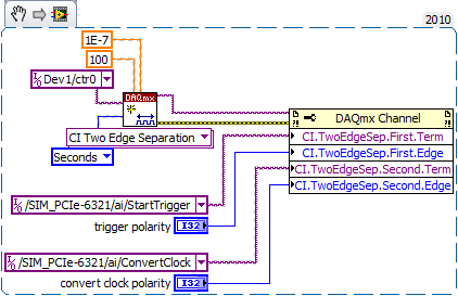
delay between the trigger and data acquisition
Hi, I use NI SMU-6368 as a tool for data acquisition. In my experience, I use an external digital trigger to start taking measures of a thermistor.
However, before the experience, I want to know the time that elapses between the detection of the trigger signal and data acquisition start time.
Is there a way to do this?
Here's the kind of thing I configure to get an accurate measure of time of t = 0 trigger signal to the
the actual first A/D conversion. It may be too much for a measurement of the temperature, but you should get
the right track.
-Kevin P
-
digital analog arm start several triggers
I trying to find out if there is a way to arm a trigger of labview to an analog signal and then actually have the trigger start from a separate, digital or analog signal. Both signals came on 2 different channels simultaneously. Research on the forums, I found that the opposite situation is possible: arm with a digital signal, then start with an analog-to-digital trigger but I have not found a way to either arm or take essentially the AND logic of the triggers two separate channels (with being analog and the other being is) as being the "ultimate" relaxation Any help/advice is greatly appreciated.
Hi, Bill Clinton.
I think you are looking for the Signal VI to export. It can be found on the pallet of NOR-DAQmx. I've also attached a document with additional information on this VI.
http://Digital.ni.com/public.nsf/WebSearch/a099c37789aacee386256e35007338e6?OpenDocument.------
Maybe you are looking for
-
MacBook Pro retina 2015 randomly freezes when try to watch the video
Hi all I bought a MacBook Pro Retina early 2015 model and is currently under OS X 10.11.4. From day one, it has been an inconsistent issue where my Mac everything would freeze whenever I try to play a video. This moved not always so I thought that th
-
application data not restored from upward
I bought a new ipad mini and tried to put in place a backup of my old camera. the restore worked, but an EA game, Madden Mobile, has not been restored. All my game progress and data are missing. I talked to the developer, EA, and they said that it
-
Pavilion 500-150: HP Bios Lock-Down?
Hi all So I was looking for forums and thought that I had asked here: so we got a new machine and the kids want to play games, but some games do not allow internal graphics. I want to install a graphics card but do not know if it will allow the mothe
-
How Group Policy to monitor the execution of any software
I want ti to restrict my users to play soltire working hours
-
At the opening of Windows Live Mail, I get an error message "Windows Live Mail has stopped working" a second error message then cuts in "a problem caused the program to stop working correctly. Windows will close the program and notify you if a solut