Trigger the FI - RIO 5641R and digitizer 5142
Hello
I am trying to generate a trigger of the my IF - RIO FPGA to start the acquisition on a table digitizer 5142. I want to do with the PXI line, but I don't have the same line in the e/s FPGA (PXIe_Trig0... PXIe_Trig6) and in the range driver (RTSI0.. RTSI6, PFI0... PFI2).
So, it is possible to do? If Yes, which line should I use?
Thank you
I found a PXI-7852R get tested. The problem was in the IF - RIO.
I found a vi in the 5641 driver to set the direction of the RTSI (entry or exit) lines. The default value is entered, now I change out and it works fine.
I wasn't a huge problem. I don't understand why we do it "manually" on this card, and why when we are simply changing the node FPGA read/write it does not change the meaning automatically.
Thank you for your help
Tags: NI Products
Similar Questions
-
My 7.0.1 program tells me there's an update available, 8.0.1...
I trigger the update that downloads an installation program.
When I restart firefox to get the update installed, restart and triggers a new window indicating that it contacts the server to update. This will continue to get in touch for 30 minutes with no established connection.
To keep my browser to 7.0.1.Windows Vista Ultimate sp2 64-bit.
Try the alternative and more simple way to download from here and simply run
-
How to measure the angular velocity, the angle and trigger using a gyroscopic sensor breakout board and LabView data acquisition?
There is a single channel data acquisition code which measures the angular velocity, angle and flexibility using a gyroscopic sensor breakout board and acquisition of LabView data attached to this, I need a help to creat two-channel data acquisition code?
Hello
Attached is a vi that you can use in order to read the measured angular position of an encoder.
If you need more examples on the tasks that you can develop with NOR-DAQmx and LabVIEW, you just need to open LabVIEW and click Help > find examples > Input and Output material > DAQmx > entry counter.
Kind regards
-
wait and trigger the first incoming digital dashboard
Maybe it's a frequently asked question, but I managed to understand the trigger DAQmx VI. Is the trigger VI supposed to block the program until Gets an edge? It waits indefinitely?
A screenshot of my failed attempt is attached to this message. I want to start my measurement (HAVE several channels) to the first incoming digital edge (or increment of the counter) on a system time real PXI. Before entering the loop of measure I want to wait for an edge (possibly indefinitely). Inside this loop, I want to begin to acquire the data values and counter of I.
I even tried to use the example, but I get an error of dialog (see screenshot).
Hello pgraebel,
The trigger VI just configures the behavior of the acquisition. So, once the start VI task is called, the task itself will be armed and waiting for the trigger. You trigger attempt.jpg, what will happen is that the task is configured and started. When starting, running VI will proceed to the loop where you call the read I. The map will wait for relaxation, with no sample being acquired until the material sees the trigger. If the trigger is never sent, the loop will iterate that you have not the VI wait indefinitely, but only for 10 seconds. Thus, if no data is received, the loop will iterate every 10 seconds. If you want to read to wait indefinitely, the value of the timeout on DAQmx Read.vi-1.
All that being said, it is not quite clear what is the problem with your attempt to trigger - everything looks good to me; are you an error? Or the just VI hang up (which could be due to the fact that the relaxation is never received)?
Let me know if it helps.
Cheers, Matt
-
How to build square 3 ph pulses and use them to trigger the two analog inputs.
Task:
1) generate continuous 1 Hz ms 45 pulses on three lines of output offset 120 degrees.
Other neighborhoods, three phases (three outputs) 120 degrees out, but instead of sine wave should be a volt 5ms 45 along with a second ground pulse. I need these impulses to control an external circuit. The tolerance of 1 Hz is loose, but 45 ms must be at 100 us.
(2) measure (trigger) two independent DC voltage over 45 ms 50 ms after each front (leader) amount of each pulse. 45 to 50 ms must be 100 us.
Other neighborhoods, begins each measure 45 ms for the DC source #1 and 50 ms for the source DC #2 after opening (rising edge) of each pulse for total of six measurements per second 1 (by 1 Hz cycle).
(3) an analog output must provide ongoing (to be booked) negative DC voltage to be used as a source of supply for external circuits.
I timely when I can generate the 45 Hz by using CO (0) 1 ms pulses continuously and the trigger I (0) on falling edge. I (0) is hard wired to triggering I (0).
How I do HAVE another (1) and two other lines (two phases) and link them to HAVE (0) and HAVE (1)?
Equipment: LabView 8.6.2, PCI-6221 (37-pin)
Hi behappy.
Thanks for posting and welcome to the forums EITHER! I think we can get what you need with the variety of the 6221 37 pins:
(1) our machines of the M series have 2 counters, so you cannot generate all the impulses of 3 of these alone. A solution would be to use outputs digital correlated.
Unfortunately, the 37 pins 6221 has only two IO digital correlated, so you should use a strange mixture of digital meters and IO to implement three impulses. It would still be feasible - for example, you might use a counter for a time base for the digital i/o lines and the other counter to the third output pulse. You would have to match the beginning of the two counters to ensure the phase of your signals.
2) there are essentially two parts to this question, so I'll try to split:
(i) combine the three impulses together to generate a single sample signal out of. I think this would be doable on a different set of M with a higher number of digital I/o lines correlated using change detection (see the user manual of M series). However, at this stage, we are just out of digital lines correlated to use, and I don't think that's possible on the 37 pins 6221.
If you use the 6221 37-pin, which you will probably need to do is to provide your own external circuits OR three pulses together.
(II) get the 5 ms delay to enjoy your second channel. Since you have already discovered that you can sample the falling edge of the digital signal for the delay of 45 ms, you would just add another delay of 5 ms before taste you your second I. You should be able to do this by setting the clock to convert DAQmx frequency (5ms corresponds to 200 Hz). The clock to convert, it's what actually sampling data (keep in mind that the boards of the M series are multiplexed).
To do this, simply use the property calendar DAQmx node, then select: more > converted > rate.
(3) this one is easy - we have not yet used all channels of AO.
So the 37 pins 6221 is a little less ideal because you have not enough correlated digital i/o to make the generation of pulses or change detection - but he has yet to do the job if you can combine the three impulses yourself outdoors and don't mind not using the additional counter to generate the third impulse.
I hope this helps, if you need any help to find relevant examples, please do not hesitate to post in return. Thank you!
-John
-
Use the button submit to trigger the validation and prompt to save instead of submit action
I want to add a Submit button that will trigger the validation using the built-in functionality. This will work as well with the "validation of forms" setting on the properties of the form. See cliché below.
However, if the validation success, I want to apply for registration dialog box instead actually submit the form using this line of code:
app.execMenuItem("SaveAs");How is that possible?

Tarek
Hello
to do this, you can simply call the function execValidate integrated, your form by using the following:
var boValidate = xfa.form.form1.execValidate ();
If {(boValidate)
app.execMenuItem ("SaveAs");
} else {}
App.Alert ("Validation failed.");
}
I hope this will help you!
-
I can't get the move animation to automatically trigger the next slide
Hello
New to Keynote. I wonder if there is a way to trigger the next slide to load after doing an animation out, that does not involve having to make an additional click? For now, I have text that moves transition and get him out on click, which then leaves me a blank screen, rather than the transition to the next slide.
Pointers or help with this would be really appreciated.
Click the background of the slide from the slide that has the text animation: Inspector > Animations > Transitions:
the value of the drop of Transition start automatically
Enter an amout for the delay, if any
-
How to trigger the dictation from the smart keyboard on the iPad pro.
I use dictated on my iPhone and my iPad quite often.
However on my new iPad Pro with the smart keyboard attached, I do not how to trigger the dictation from the keyboard.
I don't see how to get the soft keyboard back to press the button of the microphone are there, such space suggested by some on this forum.
This doesn't seem to work in the latest iOS Update 9.
I would be fine with a hotkey, or have to invoke the keyboard of the shop, then press the button of the microphone, but I don't see how do either.
When the Emoji button on the keyboard smart strike as the keyboard, the software keyboard emoji is displayed, the space but when I press the soft ABC capital but I cannot get to the regular keyboard with the microphone button.
A possible alternative would be to use Siri to dictation trigger in recording a memo or another application, space but I didn't understand how to do this job either.
Has anyone experience this problem and found a solution?
Unfortunately I had to spend a good hour on the phone with technical support when they finally admit that it was an oversight by Apple. I hope someone reads this post until they spend countless hours trying to understand something, but has no solution at the moment. Frustrated!
-
Variables shared on the CFP becomes zero and communicate with the PSC
I use a PC with two network cards, one on one wired ethernet, the other on a private IP directly connected to a PSC-2120 (running 6.0.5 full). I use variables shared on the CFP and aliasing to static variable on the PC (initially LV 8.6, now 2009f2 with the same problem in both). PC variables are stored in a database of the Citadel. I have the CFP program built to run at startup, and it works fine when not connected to the PC.
When connected to the computer all variables shared on the CFP will from time to time (almost 1/min for a few seconds) and randomly becomes zero. Even if they are resized only not to allow to become zero. I can say that what is happening because I use the variables shared as relay alarm thresholds module, and relays to suddenly slam on. I confirmed this by checking that the CFP has written to its internal flash memory card, and indeed variables suddenly are nil. On the PC it says that it cannot connect with the shared variables. This happens although LabView is not running on the PC! Manager distributed system variables shared on the CFP are listed as (disconnected) during this time, but it continues to be able to read the correct values to live of the CFP entered the module.
Interestingly, I have the same computer with the same configuration (and a PSC-2120 different) that does not have this problem. Both PC's are new from the factory. I tried to disable the second ethernet adapter, closing all wall-lights/virusscan and re - order network cards in windows networking/advanced settings without success. Simply disconnect the cable between the PCP and the PC does not cause this problem and shared variables become zero does not trigger the network on the CFP monitoring parameters.
My questions are:
(1) this problem can be fixed?
(2) lost communication for a few seconds is OK, but given the PSC variables become zero is not. Can I stop the variables of the PSC to become zero?
-David
To update my previous post, it turns out that the re-installation was not the solution (the problem of variables start again occurring began). I finally realized that this only happens when I put the CFP time server IP (under Additional Configuration to the MAX). I was upgrading the server time on 192.168.1.1 IP (the IP address of the adapter of the CFP has been directly connected to). However, this compensation setting solves the problem.
I do not think that the time on the CFP must need to be addressed too often (and perhaps it is synchronized if I never re - deploy files to the CFP?), so I guess that leave it empty. Curiously, I have the same setup time on an another PSC server IP and PC (running LV 8.6) without problem.
-David
-
That really means the vertical range? And the gain factor?
The NI PXI-5102 digitizer: that means vertical range really means, it is the range of voltage of the signal to be measured or the signal to the ADC input terminal?
How to control the gain of the digitizer? And what are the factors that can affect the gain?
The portrait is located between the valid entries range of the digitizer on that channel. If you set the interval to a value that is not valid, it will be converted to the next highest value. This is the way you control the gain of the digitizer. It is easier to define the vertical range on the maximum expected range of your input signal and allow the driver to NO-SCOPE compel the beach to the next highest value. This allows you to use your code effectively with more than one type of digitizer (5102 and 5112). For example, you know that your input signal has a range of 3 v (+/-1.5V). Set the vertical range at 3. OR-SCOPE that will force to 10V, the next beach valid more high for the 5102. You can find the valid vertical beaches for your device in the folder of Documentation OR-SCOPE in your Start menu or online.
Mitigation on your scope probe will affect the vertical range of the device. If you have a 10 X probe and defined the vertical range to 10, the actual vertical scale will be 1. You can have NO-SCOPE figure that out for you by setting the mitigation of the probe with vertical Configuration.
More information on the routes of entry, and gains are available in NO-SCOPE help about using vertical configuration.
-
How to synchronize the start of IT and relaxation the Scan list (DAQmx Switch)
Hello
I want to measure samples of N to the AI0 of Council NI PXI 4461. The measurement starts on a rising edge of a digital triggering provided to the PFI0 of the same Board. The measure is configured with samples of N/2 pretrigged. So far, everything is under control...
Using an NI PXI 2567 Board, the signal applied at the entrance the 4461 (AI0) switches between a V2 and V1 signal. I would like to synchronize the switch between the two signals with the trigger signal applied to the input of the PFI0 Governing Council 4461. In order to obtain samples of N/2 of V1 and V2 samples N/2. Synchronization of 1 to 5 ms would suffice!
My question is how to synchronize the start of acquisition of AI pretrigged of 4461 with the switch control given by the Council of 2567?
Thank you in advance for your help...
PS: the configuration of the system is:
-LabView 8.5
-Chassis PXI-1044
PXI-4461 on slot 2
Module 4-slot PXI-2567
Hi Frederic,.
I came back to this recently and used the following examples to run the desired synchronization.
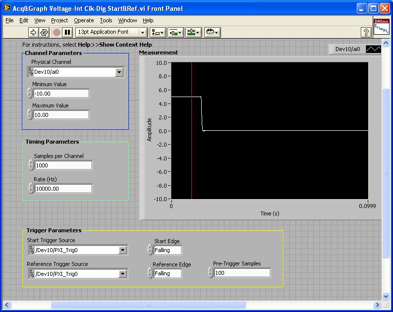
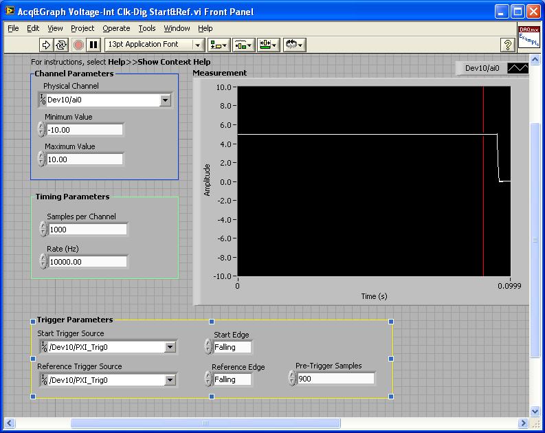
PXI-4461: Acq & graph tension-Int Clk - dig Start & Ref .vi
Samples per channel = 1000
Rate (Hz) = 10000.00
Start the trigger Source = / [name of the instrument DAQmx] / PXI_Trig0
Onboard start = fall
Reference Source Trigger = DAQmx Device Name] / PXI_Trig0
Reference edge = fall
Trigger samples = Variable (100, 500, 900)
PXI-2567: Switch Scaning-SW Trigger.vi
Advance the output terminal full = / [name of the instrument DAQmx] / PXI_Trig0
Scan list = / [name of the instrument DAQmx] / ch0-> com0.
Scan list = / [name of the instrument DAQmx] / ch1-> com1;
Hardware configuration:
The PXI-2567 module controls an external relay that switches between the voltage of 5 V on ch0 and ch1 0 V.
The PXI-4461 connects to the COM of the external relay and therefore reads 5V when ch0 is connected; 0 v when ch1 is connected.
Procedure: The above examples are used in the following procedure.
1. run the PXI-4461 VI. A start trigger (falling edge) is necessary to start collecting samples before firing.
2. launch the module, PXI - 2567 VI. When ch0 is initially (and immediately) on com0, a trigger is sent to PXI_Trig0. The PXI-4461 will begin to acquire samples before firing.
3. - click on the "Connect to the next" button on the front of the PXI - 2567 VI module. This sends a trigger to entry software for the PXI-2567 module and the transitions of the scan for ch1-> com1 list. Once the PXI-2567 module remains (debounced), advanced complete relaxation is sent on PXI_Trig0 for the PXI-4461. The PXI-4461 will begin to acquire samples after outbreak.
Note: Instead of the trigger of the software entry, an external input trigger can be used (e.g. PXI_Trig1).
Results:
> Before instant release of samples = 100
Delay is caused by the time of actuation of external relay.
> Before instant release of samples = 500
Delay is caused by the time of actuation of external relay.
> Before instant release of samples = 900
Delay is caused by the time of actuation of external relay.
I hope that the attached screws and the explanation above helps you and/or other customers who have this problem.
Best regards
Chad Erickson
Switch Product Support Engineer
NOR - USA
-
How to collect data on the programs of LabView and VC ++ at the same time?
Hello
There are two programs in LabVIEW and another is in VC ++. The two programs to collect hardware data.
Therefore, for the experience, it is necessary to begin to collect data at the same time and lag must be
less than millisecond (it is essential for the experience). How can this be achieved? BTW, I'm new to LabView.
I think on the use of network socket to get the message for both applications.
I was wondering if there is a better way.
Thank you.
MARK002-MAB wrote:
Hello
There are two programs in LabVIEW and another is in VC ++. The two programs to collect hardware data.
Therefore, for the experience, it is necessary to begin to collect data at the same time and lag must be
less than millisecond (it is essential for the experience). How can this be achieved? BTW, I'm new to LabView.
I think on the use of network socket to get the message for both applications.
I was wondering if there is a better way.
Thank you.
You do not say if two programs access the same material, but I guess not. Because if they did, you probably get conflicts when the two programs try to access the same material at the same time.
In either case, the only really reliable way to ensure that your needs of< 1ms="" would="" be="" hardware="" triggering.="" one="" hardware="" unit="" is="" programmed="" to="" provide="" a="" hardware="" trigger,="" typically="" a="" digital="" signal="" and="" the="" other="" is="" programmed="" previous="" to="" the="" desired="" start="" point,="" to="" wait="" for="" that="" trigger="" and="" start="" automatically="" when="" it="" is="" received.="" if="" both="" hardware="" units="" are="" ni="" daq="" cards="" you="" can="" do="" that="" fairly="" easily="" using="" the="" rtsi="" bus="" or="" in="" case="" of="" pxi="" the="" pxi="" trigger="" lines.="" if="" they="" are="" different="" hardware="" then="" it="" can="" get="" more="" complicated="" to="">
-
How to trigger the value change in the structure of the event
HII everyone, like the title, how should I trigger the value change event to display a message... Here is my connection... I want to trigger structure of the event to bring up the subvi, when the flame and the led are TRUE State... I have using the node property, but still not able to run event structure... How should I connect? Thank you very much...
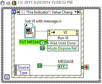
There are several ways you can do. First of all, you need to configure your sub - vi while he does everything you want when you run (in the properties of vi, top most window for example) and to make sure that it closes completely when you're done (when you click on the 'OK' button, for example).
Spend you need an asynchronous call to the subvi. There are several ways to do so. My favorite one below. You go in the palette under 'Application control' and select a static reference VI. I like this approach because it keeps track of the way subvi for you, as long as the subvi is in the same project. Then, drag the sub - vi on the empty square which will be changes to your sub - vi icon. Then, you connect to an invoke node in the same palette under and select run VI. "Wait, that 's" set to false and the main VI will continue to function after the start of the vi of Sub. Together "Auto Ref" is the best way to go. Otherwise, you will need to follow the sub - vi reference and shut up yourself when you are finished.
-
Structure of the event with gray and disabled controls
I'm working on a data acquisition program that uses the structure of the event to manage the graphic user interface. I have a 'start logging' button that raises an event when the value changes and starts to collect data. While collecting data, the program disables and gray on all controls on the front panel except the button "stop logging" that ends a while loop with in the event of data logging. If this event is active only when you press "stop recording." There are other events that are triggered by a mouse up/down, action others controls disabled on the front panel. The problem is that, while the program collect data if you click on one controls disabled and gray that has a mouse up/down, event, the program seems to hang and will not push the button ' stop logging. I don't know if his attempts to run another event, but he continues to logging data, I just can't stop it. I have to use the Cancel button to stop the program.
The real problem is that a control, even when disabled and grayed out, can still trigger a mouse to the high-low event - controlled, it true? Also, what happens if an event is raised during execution, another event my understanding was that a single event can run at a time.
Thank you
Doug
Doug,
By reading between the lines, here a bit... Looks like you have your data collection and logging code in the box to Start Logging event. If so, this is part of the problem. No other case of event cannot run until this one is over. Move data collection and the registration code to a parallel loop. Have this loop to sit in an inactive state until you press the Start Logging button. Then, in case for the button change send a command via a queue to the loop of logging and out the case of the event. The event loop is then immediately ready to respond to the next event.
Generally the code within a case of event should run quickly, no more than 10s of milliseconds for maybe 100 ms to avoid slow response to another event.
Look at the producer/consumer (events) design pattern which comes with LV for an example.
Lynn
-
Unable to trigger the nissin Di622 flash Canon 430ex II
My gear is Canon T1i camera, flash for Canon 430ex ii, flash Nissin Di622 (1st model) and radio trigger CowboyStudio (I don't remember the model).
The 430 in ettl mode & on the camera will trigger the camera 622. The pop-up flash will trigger the camera 622. The 430 on camera & manual mode will not trigger the 622 camera and the camera 430 will not trigger the 622 in any mode.
The radio trigger fires the camera 430. I want to trigger the camera 430 with the radio and have the 430 then trigger the 622. Is there a way to do this?
I thought that most of the flash units can be triggered by a Flash of light such as the pop up flash. I wouldn't be able to trigger the 430 (in all modes) with the pop-up flash?
No, some Nikon and other 3rd party flashes can be triggered with a simple flash, but not Canon. Your 430EX II won't work as a "slave" If you have a 'master' that uses the system of Canon wireless. Slave Flash gun can operate using coded light signals of the "master" flash Cannon
Some newer Canon cameras have a built-in pop-up flash that can act as a "master" of Canon, but your T1i does not work like that. Canon cameras that will make this are the T3i, T4i, T5i, 7 d, 60 d, or 70 d.
You can also buy a Canon flash which can be used on your T1i and acts as a "master". It's the Canon 550EX, 580EX, 580EX II and 600EX-RT. The cheapest Canon ST - E2, which can also act as master but does not have a Flash.
There are also a few 3rd party flashes as Yongnuo, Nissin and Metz who can also work as 'master' using the gun system.


Maybe you are looking for
-
After reading the privacy statement from Microsoft regarding their Silverlight 5, it has troubling information about the loss of his privacy, under the "collection and use of information...". "the personal information and the information on my comput
-
Satellite X 200 and replace the HD-DVD player
G ' Day I'm looking to replace the HD-DVD drive in my Toshiba X 200 (PSPBUA-00N007) with a Blu - Ray player (or burner). They are on the market yet and available at Toshiba (or, say, eBay)? What should I look for? The HD-DVD player is a cool historic
-
I changed my phone number and e-mail address 3 or 4 times trying to move away as spam and people to hack accounts. I contacted T-mobile, ATT with no result. Get emails from. Phone number of Jones.Julia475 of Gmail (deleted). I blocked them but still
-
I was contacted by phone by a foreign speaking gentleman who carefully took me by security on my computor records. He ended up giving me an error code 800 418 20 and of course this code was not active on my computor so he told me that if I am connec
-
runtime error when you add a softmotion axis
Hi all I am running labVIEW 2010 with the development softMotion, creating a compactRIO application module. When you try to add an axis softMotion in Project Explorer I get a window with the message "Microsoft Visual c ++ runtime library." Run the er