Understand a Lock-In Amplifier
Hello
I wonder if someone can help me to get the full idea of a Lock-In amplifier. I am trying to isolate traces hidden in the noise signal and think that this may be the way to go.
So far, it is my understanding:
I multiply my signal with another signal, through a psd, use a low-pass filter and get the DC of the weaker signal that I wanted to? Is this good? I'm not sure how I should go about it with LabVIEW well. I use a cRIO. Should I configure a sine wave of amplitude of x and frequency of y and multiply that by my signal comin cRIO, then place it thorugh a FFT & PSD VI? I looked at a few papers and exmaples, but miss me something and not too course, where I get lost. Any help would be greatly appreciated!
Kind regards
Kelly
Hi keLOb,
There is an example of good community that describes how to implement a detent amplifier using labview, as well as to provide the source code which can be found here:
https://decibel.NI.com/content/docs/doc-1762
The example was set up on a cRIO by programming the FPGA, so this should certainly guide you in the right way. You can pass by the example and ask questions if you are unsure about any specific section of code.
Thank you and best regards,
Tags: NI Hardware
Similar Questions
-
question on locking of LabVIEW amplifier design
Hi all
I use myDAQ with the NI DAQPad-6259 pinout for the input signal measurement. and I want to build an amplifier to lock by labview to measure the input signal. Does anyone have this kind of tutorials or vedios that enjoy helping me build this? I didn't use the Toolbox, but trying to figure out how to build and why it should be.
Thank you.
Look here:
http://www.NI.com/white-paper/5613/en/
http://forums.NI.com/T5/dynamic-signal-acquisition/lock-in-amplifier/TD-p/1057126
http://forums.NI.com/T5/LabVIEW/lock-in-amplifier-using-NI-USB-6251/TD-p/1550972
http://forums.NI.com/T5/dynamic-signal-acquisition/lock-in-amplifier-and-DAQmx/TD-p/282419
-
SRS problem lock at the labview program amplifier with regard
Madam, Sir, I have a labview program for SRS 830 lock in amplifier and problem is that the output is depends on the sensitivity... as we change sensitivity 500mv to 1v then exit hydro-huileuses changes. automatic gain function does not work. I'm so amazing that, about what the sensitivity, the output is correct. Please, help me to overcome this problem by starting the function of automatic gain. I enclose you than vi. When I run vi to autogain, then it displays an error and stop.
'This error' mean? Time-out error or a parameter? If it is a parameter error, definitely check the manual to see if this is supported.
-
can I set up an amplifier to lock using the PCI-7831 RIO map?
Normal 0 21 MicrosoftInternetExplorer4 / * Style Definitions * / table. MsoNormalTable {mso-style-name: "Table normal" "; mso-knew-rowband-size: 0; mso-knew-colband-size: 0; mso-style - noshow:yes; mso-style-parent:" ";" mso-padding-alt: 0 cm 0 cm 5.4pt 5.4pt; mso-para-margin: 0 cm; mso-para-margin-bottom: .0001pt; mso-pagination: widow-orphan; do-size: 10.0pt; do-family: 'Times New Roman' ;} "}
Hi all
I use FPGA, PCI-7831R module, I can implement locking an amplifier using the PCI-7831 RIO map?
Kind regards!
SUN
Hey,.
The following link shows an example of a lock-in amplifier set implemented on a cRIO with 9233 module.
-> http://decibel.ni.com/content/docs/DOC-1762
Hope this helps,
Christian
-
Block in the amplifier with high material sampling rates no DSA
Hello
I intend to use the starter kit OR locking amplifier to detect a harmonic signal of 400 all about. I intend to use the PCI-5105 digitizer (I don't him have not bought until now, but I will soon). The start kit lock, I downloaded and unpacked the files and was hoping to give it a try with an NI USB-6363 however the vi does not open because it says that there are a lot of sub - VI lack (Subvi read.vi I HAVE... clear.vi, etc.). The LockinDemo.vi also seems to use NI 4472 as a default material. My questions are if the lock-in-amplifier starter kit OR 1) can be used with PCI-5105 and 2) cannot vi missing of the be downloaded from somewhere or be replaced by other blocks on mine?
Thanks in advance for any help
Benoit
Hi Benoit,.
First to start development with LabVIEW Real-time, you can check if your system supports LVRT. You can make use of RT disk utility that will test your system as shown in this article: http://digital.ni.com/public.nsf/allkb/9209361E17708D548625744A007FF353
We have lists of equipment belonging to systems tested here: https://decibel.ni.com/content/docs/DOC-10692 and you can always check for the other hardware compatibility here: http://zone.ni.com/devzone/cda/tut/p/id/8239
We do not have a driver available for the PCI of pledge cards but if these cards use VISA calls, you can develop and LVRT recognizes your card by following the KBs:
(1) acknowledge the third peripheral part with LVRT: http://zone.ni.com/devzone/cda/tut/p/id/3142
(2) expand LVRT peripheral Driver PCI: http://zone.ni.com/devzone/cda/tut/p/id/3251
I hope this info helps!
-
Want to use Lock-in detection with a linear detector with diode bars
Hi people,
I work with OR lock virtual amplifier to build a detection system that uses a linear led strips detector to measure the effect of an electric field on the spectrum of a molecule absorption. Traditionally, this technique was carried out using a single photodiode detector connected to an external amplifier of detent and the absorption spectrum was analyzed using a spectrometer. The lock would demodulate the signal of interest based on the wavelength. In my setup, I acquire any range (all wavelengths) simultaneously to speed up the experience and improve S:N. to do this, I use a spectrometer OOptics USB2000 + and NI virtual LIA. Each element of the photodiode array, then acts as a unique photodector calibrated to a specific wavelength. I want to demodulate the signal of interest of each element of the matrix of the photodiode.
After reviewing several of the messages on this forum, I start to worry if my setup actually work. So far, I have seen that everyone uses a detector single channel connected to a card scanner of some sort, which also acquires a reference signal. Phase delays would come mainly from electronics and cable lengths. In my setup, the detector is digitized by the 2 MHz ADC in the spectrometer OOptics and my digitizer OR is only to measure the experience reference signal. Because two ADC of separate instruments are used, this prevents the use of the vLIA? My intuition tells me that don't know, but I am relatively new to the use of detectors photodiode array for this purpose.
Any help would be greatly appreciated.
Timchem
Tim,
Now we are getting somewhere.
The effective sampling rate is about 70 Hz. Unfortunately, the time is probably metered software, which introduces additional jitter at the time of each data set. Sampling a signal to the Nyquist rate only gets you the minimum information on this signal and certainly produced very little significant phase information.
Given that the intensities of the pixels are measured at the same time, you have no worries for the phase shifts between the pixels.
Question about the synchronization: the spec introduces a measure whenever it receives a TTL pulse? Integration of 1 ms, then send 2048 data points, then wait for the next pulse? Assuming that's what he does, then you have a chance to lock a verrrrrry slooooow amplifier.
It would work something like this. Setting the sync generator to produce a measure trigger pulse every ms T, where T > 13 + 1 ms. Suppose that T = 20 ms (FLA = 50 Hz) to keep simple mathematics. Sets the modulating frequency to 1 Hz. Then you get 50 samples per period of modulation, or sample all 7.2 degrees.
Now I need more. You indicate that your alternative signal is microvolts. What is the significance of the component continues? The relationship between these two signals is the signal to noise ratio. A quick glance on Ocean Optics web site indicates that dynamic range for a single purchase is 1300: 1, which seems low for a device with a 16-bit A/D converter. This must be the limit of the photodiodes to an integration time specified. If the signal is really limited to this range, you can get into trouble. The lock-in amplifier depends on some signals actually being there, just smaller than the noise. In this case the limitations of photodiodes or the processes scanning spectrometer, it is possible that there are really no signal there to extract.
If your signal is a quantity equivalent to 10% of the dark current, you must get a signal you could accurately measure on average for about 100 cycles of the modulation frequency (1 Hz) to start. Your samples are stable for 2 minutes or more?
A different instrument may be the best bet.
Lynn
-
CFLock identify anonymous locks and latches
I'm new to CFLock, but have recently read on staves cflock and variable, etc. I feel that I have a solid understanding of the situation. In the documentation, I found this snipit I'm having problems understanding.
"Lock scopes and names.
The cflock tag prevented concurrent access to sections of the code, not variables. If you have two sections of the code that access the same variable, they must be synchronized to prevent them from running at the same time. This by identifying the locks with the same scope or name attributes.
Note: ColdFusion does not require you to identify exclusive locks. If you omit the identifier, the lock is anonymous and you cannot synchronize the code in the tag cflock with another code block. Anonymous locks do not lead to errors when they protect a resource that is used in a single code block, but they are of bad programming practice. You must always identify read-only locks.
"
When they are referring to the anonymous locks, they suggest that you use the name option compared to the scope within the cflock tag option? See the examples below:
< name cflock = "Logoutcount" type = "exclusive" timeout = "10" >
< cfset application.logoutcount = application.logoutcount - 1 >
< / cflock >
OR
< cflock scope = "Application" type = "exclusive" timeout = "10" >
< cfset application.logoutcount = application.logoutcount - 1 >
< / cflock >
I guess that if the scope and / variable were the session level, I would just change the application to the session.
What I'm trying to get clarification on here is as well, herds must be created using the name attribute or the scope attribute. I can't find much in the way of documentation pertaining to this matter.
I think you're right. After I read your response, I re - read. I missed the sentence as follows "You do this by identifying the locks with the same scope or name attributes.".
Thanks for pointing it out. Makes sense!
-
Hi guys,.
I keep coming across these two terms, and I'm trying to conceptualize their. I understand why locks are needed on the resources (to me, this means tables, index, lines, sequences etc - maybe something else?). But I don't really know how to locks and latches should go. I have collected the following Googling autour.
VALVES:
Provide exclusive access only to the protected data structures
Request are not aligned, if a request fails, process, try later
Simple data structure
Protect the resources that are briefly required (LRU list)
Very effective
LOCKS:
Allow serialized access to some resources
Lock requests are queued and serviced by order
Complex data structure which is still protected by latch
Protect the resources for a long period (e.g. tables)
Less effective
If someone could give me a simple example to tell a very simple table and show how the lock and the lock will interact for a query on the table, it would help me a lot.
Thank you.Dear Oracleguy777,
Your welcome at any time, and Yes, this article of H.tonguc YIlmaz is excellent.
Soon :)
Francisco Munoz Alvarez
www.oraclenz.com -
I'm working on the implementation of new equipment, a second facility that we have. In both configurations, we use a single GPIB-ENET/100 and a GPIB-232CV-A with LabVIEW. On the original configuration, which works very well, here's the order of connection:
Computer--> GPIB-ENET/100, connected via an ethernet cable
Power supply high voltage--> Lock-In Amplifier--> GPIB-ENET / 100--> GPIB-232CV-A, Garland with GPIB cables
The GPIB-232CV-A has a dip switch address 1 and also runs a cable DB-9 to a series of commands of stepper motors. In my global addresses VI, these stepper motor controls receive a global address of 1, what I understand. What I don't understand, is why the high voltage has an address of 3 and the Lock-In has an address of 4, which my other VI scream in order to communicate with them. That this has something to do with the order of Garland? Yet once, there is only a single use GPIB-232CV-A, and it has an address of 1. Thank you.
Too bad, my devices have internal GPIB address
-
What is the headroom of the DAQ 4431?
I use the 4431 with detent multichannel VI.
No one knows what is the headroom of this system, when it is used as a CER.
Is it possible to read what is the headroom?
Hi Ddallen,
Could you explain how you would define headroom? If it's because I believe (the largest ratio of the signal to the input signal interference), it is not specified because the lock-in amplifier is a defined software and therefore according to the parameters of your choice that can make a difference in this value. Headroom is a term used for blocking amplifiers would not therefore necessarily an aspect of map of 4431.
-
Best way to code structure to control several instruments
Hello
I am a novice but not inexperienced labview programmer. I'm writing a labview code to control a physical optical experiement. This involves writing a GUI which of your interfaces then with a variety of instruments (such as motorized turntables, lock-in amplifiers, power supplies, Renault, etc...) all connected to the computer through various means. All the instruments are delivered with their own labview drivers to complete their most important functions. Essentially, the instruments will operate independently, but occasionally, will be a set of steps involving several instruments (such as move, take a step, move again,...)
My question is what is the best way to structure the top level VI where all GUI controls? I have currently the code structured so that each instrument has an event structure that manages keys and commands for it. Simple events like the movement are dealt with in the cases where structures themselves while queues and occurrences are then used to handle more complicated events in external loops. It is an appropriate way to handle this scenario, or is it that most commonly architecture?
Thank you for the help
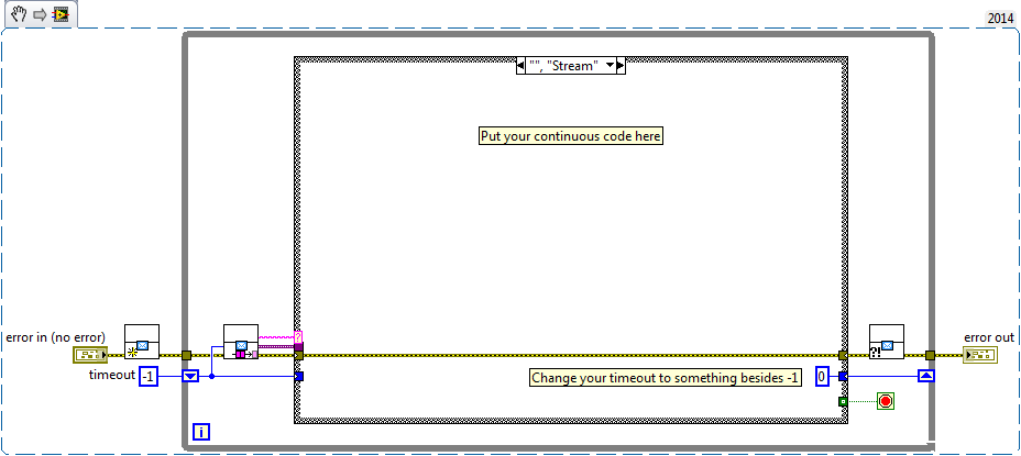
You play with fire when using several structures of the event. My preferred method for executing an instrument that has a 'stream' mode (example: a spectrometer where you always see the spectrum), is to provide that it is a clean line, with a dequeue item. The 'element' may have a message part (or State) in the form of an enum or string, as well as some data in the form of a Variant. You want to set a parameter, you could send a cluster containing the enum "Set the parameter" as well as the value of the parameter in the form of a Variant. The default case would be to get a spectrum and update a graph (or send another message to a user interface management loop that updates the chart).
You can open the project template QMH who comes with LabVIEW to see how a line would work, and then you can add multiple queues for different instruments. I keep the new loops in their own SubVIs and reference to the queue in a global functional to clean the main schema.
Here is an example of what your data of the module flow record might look like (the string constant empty considered double quotes is by default to expire the message dequeue)
-
Can I use SMB connector in cRIO 9012 as an external trigger source to excite my system?
I use the clock real time of a cRIO 9012 for generate two pulses with a deadline given to fly a lock-in amplifier. Unfortunately, the jitter generates a beat that gets worse the ratio of SN. I would like to use an external source to trigger the system and reduce the jitter. Can I use SMB connector for this?
Hello
What color is the status light? It is green or amber? According to the manual, a solid status light means the cRIO met a fatal error, which could mean a lot of different things. After you reformatted, you redeploy the code that started this issue? If so, I would try again and do fitness then deploy your exe to boot. In addition, you might want to try to restart the cRIO with the no app switch flipped on the position 'on' and see what happens.
Another good troubleshooting step is to get information via the serial port. Here are instructions for how to do this. If you attach this information to this topic, I can take a look.
Thank you
-
Problems on Mac OX 10.6 V.S. Windows XP SP3
Hi all
I have a problem with my MacBook Pro.
My system is Mac OX 10.6, but I use BootCamp to 10.6 to implement the portable Windows XP SP3 on the same computer. Then I put in place LabVIEW 8.5.1 on Windows XP system and use Agilent 823578 USB/GPIB Interfaces to communicate with locking SR830 amplifier.
When you use Angilent connection Expert, I could communicate with SR830 by Agilent 823578 USB/GPIB Interfaces. However I couldn't use relative visa in LabVIEW command, such as opening VISA, to connect with SR830.
On the other hand, I use the same program on the DELL Windows PC to communicate with SR830 without any problem.
So I was wondering is it a problem of compatibility of MacBook Pro and Mac OX 10.6 with Driver of instruments?
I will be appreciated if someone could help me to solve my problem. Thanks to you all.
First, you must enable support for Tulip so that MAX recognizes the controller of agilent. In MAX, you select NI-VISA under the software section. Click on the visa, and then under MySystems Options > General settings, select passports. Check the box for NiVisaTulip.dll. If you do a view > refresh, the controller must be included so that you might have to restart. When MAX lists the agilent controller, you should be able to scan for instruments. It's what will update the visaconf.ini file.
I'll sort of memory on it and have only done on windows pc. I don't really know if there are problems with it under a virtual machine on the Mac. There are numerous links on tips related to the use of controllers of agilent with LabVIEW so you can do a search to see if I missed the details.
-
Read a data point every time via the sound card
Hello!
I'm reading the output of an amplifier to lock that cannot be connected to my PC. So I decided to read througn my mic.
To do this, I connect channel 1 or 2 for my microphone.
However whenever I do a reading I can not simply take a while but only several points at once.
10 is the minimum number of points I can get when I put the sampling of 100 and length frequency 0.1 in the VI of its acquisition.
Any combination that translates into less than 10 points gives me an error (for example 100 sampling rate and duration 0.01).
I thought that by indexing dynamic data to acquire its VI would solve the problem, but playback is differnet from that I get when reading lock-in amplifier
through GPIB.
(I'm testing with a locking amplifier which I can via GPIB interface. So at the same time, I read with my sound card and the GPIB and compare graphs)
Any way to read a point every time? Or I'm getting something other wrong here?
Thanks for your time!
Looks like the CDA min frequency response of 10 Hz, pg 69 card technical:
http://www.hardwaresecrets.com/datasheets/ALC888_1-0.PDF
However, you can apply a known value of low voltage DC at the entrance to see if it reads properly micro. Note that microphones out low level signals, looks like the ADC full scale entry is ~1-1.5V so make sure that your entry does not exceed. You can use dividers of resistive voltage if necessary to reduce the input voltage.
-AK2DM
-
How can I create a loop with delays in the series?
Hi all
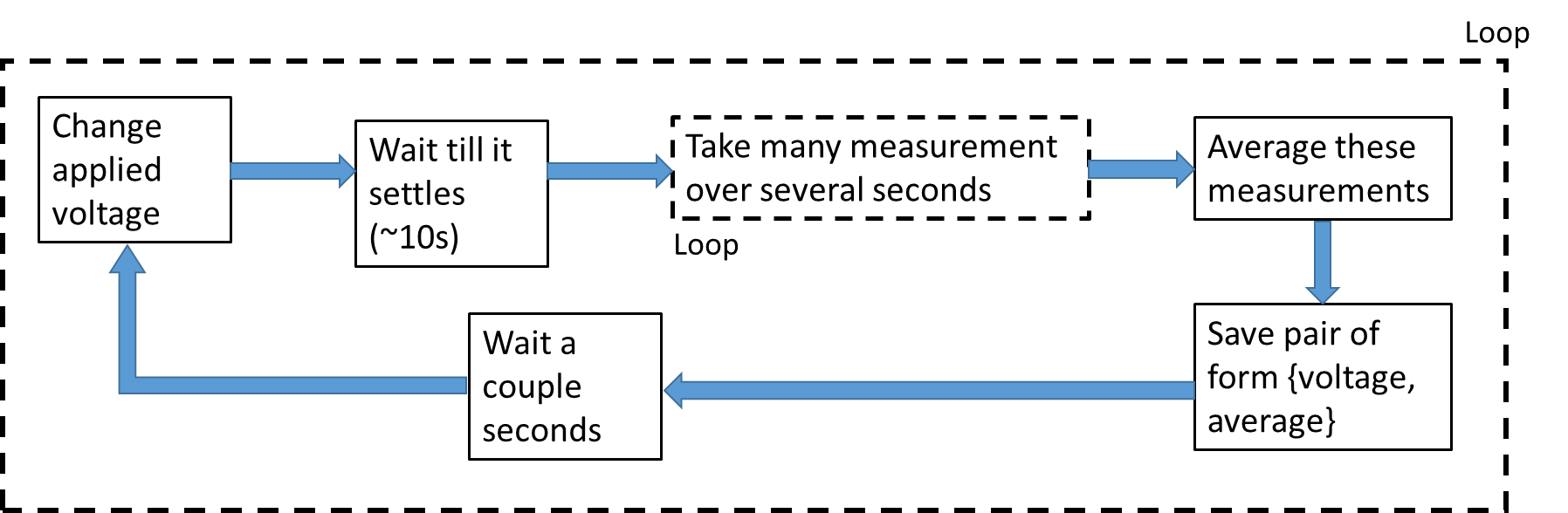
So I wrote a Labview program to control both machines. Very simply, one is a source of tension, and the other is a Lock-In amplifier. What I want to do is change the applied voltage, wait a few seconds for the response of GARLIC to settle, then take a number of measures of GARLIC, then those on average and save to file.
Here is a flowchart of what I mean:
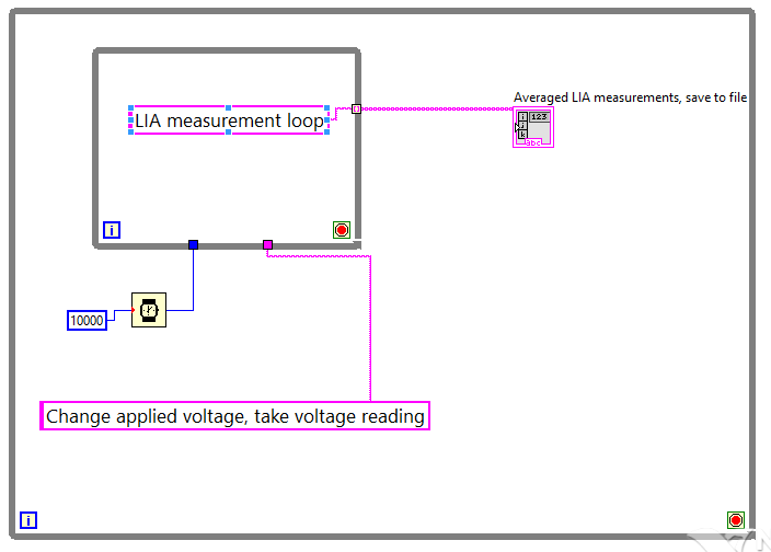
I did it for the most part, but I'm having a little trouble with the delay. VI file is huge, so I tried to make a simplified architecture that shows the basics of what I do:
(The string and the constant matrix constants aren't actually what I use, it's just to illustrate, because I don't know how to make a quick easy space reserved for diagrams... is there an easy way?)
So my assumption here (and it seems that it is happening) is that, for each iteration more outside of the loop, the first thing it does is start the countdown and start the change applied voltage/etc. at the same TIME, right?
And then he only goes in the loop of measure LIA once she completed both of these tasks, right? (Please correct me if I'm wrong!)
Then, how would make a delay after the loop of measure LIA? If what I've said so far is correct, then if I put a 'waiting' in the main loop, I don't think that it works (or at least not be very specific) because he would begin as soon as the iteration, would therefore be cash while GARLIC measured, and so do not wait the right amount of time after the loop LIA was finished (if I even put that it is long enough that it was still underway after This loop was completed).
Am I correct in what I said?
What is the smart way to do this?
Thank you!
You're right about the order data flow, which is usually the fall of most starting LabVIEW developers.
To add a wait behind the inside loop, ask a node pending within a structure (the simplest being a structure flat sequence) and add some sort of data flow from the output of this loop to the structure of waiting. This will force this structure will not work until the loop ends.
That being said, there is a better way to do this. Look in the Simple State Machine with LabVIEW 2012 and more recent architecture model.
Edit: NIquist beat me to it.
Maybe you are looking for
-
I can't open the files in the folder "my pictures."
For the last two weeks, I was unable to open the files in the folder "my pictures." For example, if I save the photo in my pictures, it will not open if I double click on it.Someone at - it ideas?Thanks in advance.
-
My wireless and mute, volume up/down buttons have stopped working together.
I have a HP Pavilion dv6-2113TX, and all of my upper buttons (mute, volume scroll and wireless area) have stopped working. I fall there are about 3 weeks and not very high, only about 1.5 ft, but I worry that this may have had something to do with my
-
My computer seems to work very well, but on my desktop there is always a message in the lower right corner of the screen. never had a problem until about a week ago. Help, please!
-
Unable to connect Blackberry AppWorld on BlackBerry Smartphones
I can connect my legacy but to the 2nd floor when my PIN code and I submit error message so I cannot go further... How to solve it, please,
-
Golden Star of blackBerry Smartphones
On my home screen next to serch and profiles where it would show you had failed calls and upgrades 5-pointed Gold Star hollow in the Middle appeared and it seems 2 b using a lot of battery power what is a how can I make sure that she?