UP2716D, calibration with Spyder5Elite?
I was just request if it's a good idea, or necessary, calibrated my desktop PC, with my Spyder5Elite software, when it is connected to my Ultra strong UP2716D monitor.
I ask this question because this monitor is calibrated at the factory to equipment. TI have set the monitor to the Adobe RGB color space
I would just in the calibration with the Spyder5Elite of thinking would only make changes to my graphics (GeForce GTX 970 4 GB graphics card) card and not on the screen.
Sorry if this is a silly question, but it's my first monitor with hardware calibration.
Our software changes the LUT (Look Up table) in the monitor CAL1 and CAL2. Read the User Guide on page 40.

Tags: Dell Peripherals
Similar Questions
-
PCIe-7852R and OR USB-7856R OEM Calibration with Calibration Executive
Can I calibrate PCIe-7852R and NI USB-7856R OEM with NI Calibration Executive?
How?
Our version of National Instruments Calibration Executive Software is 3.5 and it has no procedures to OEM PCIe-7852R and NI USB-7856R products.
Hello
There are several ways to calibrate your instruments.
First of all, the help file for the calibration of R Series devices to the Calibration Executive can be found by navigating using the Executive of Calibration > calibration device > data acquisition (DAQ) devices > NI dynamic signal Acquisition > NI R series calibration procedure
You can also follow the instructions in the following document.
http://www.NI.com/PDF/manuals/372004d.PDF
Finally, you can also calibrate your software for the R Series devices using the calibration installed with the drivers. You can get "calibrate the device 78xxr" and run the executable file to calibrate your devices.
Thank you.
Kind regards
Nigel
-
Calibration with NI9237 and NI9944 strain gauge.
Gentlemen.
I have a cDAQ9172 OR with NI9237 and the bridge 1/4 NI 9944. Practically, I'm working on measures of strain gauge issues using a strain than 120 ohms connected to the NI9944 to build the bridge half happening inside of 9237. I have a continuous doubt how is the calibration for the strain gauges. The manual speaks of a shunt resistance which, in the case of NI9944, is already in the system. The manual says that I don't have the shunt resistance external nee. It is clear.
My question is this:
the menu for calibration requires a resistance value that I don't know, I'm leaving in the value proposed by the menu of NOR. The strain gauges takes easily compensate, so I always have to recalibrate the channels in the NI9237. Is this normal? Can a (application to 2.0 V strain gage) voltage of 2.5 [V] generates a continuous drift of the measure?
Strain gauges are: EA-06-125BT-120
Hi cgenco,
Because the NOR-9237 with 9944 uses an internal resistance for shunt calibration, you need not to worry about the value of the shunt resistance. Take a look at the following article that specifies how connections are made. Calibration article will show you the basics behind how to exploit.
Also, since there is a ratiometric measurement, the voltage is 2.5V shouldn't matter as long as your pawn takes care of everything.
-
Calibration with the voltage source - float connections
Hello
I want to calibrate a PXI-6133 DAQ with a floating voltage source. It says in the manual of the calibration connect the positive output of the Stallion to the AI + pine. Since my source of tension is floating I connect the negative output to GND. HAVE I - HAVE GND short or leave - not connected?
Thank you
Jens
Sorry, I just answered this question for my part it is logical to short-circuit the entries HAVE - and GND.
-
I have a lot of trouble recently with the release of the color range in Photoshop CC. The software is updated. I used to the Datacolor years to calibrate the system, and it worked well always. But now I noticed that I have a lot more images with out-of-gamut colors, and it prints wrong. Is this a problem with Adobe? The rest of my equipment is the same. Any help? I'd appreciate comments. Thank you, Emilio.
First, the range warning applies to the proof profile that you put in place, under test format. If this is not the profile that you want to print with, there is no relevance.
Second, range warning is a very large and imprecise indication, and I would just turn off. It shows what is out of range, but not how much. There are better ways, like proofing (even once, test format, toggle with ctrl + Y).
You can also convert a copy of the file to print your profile and look at the histogram. If you have severe cuts, you can adjust the file accordingly.
Third, there are people who feel the effect of threshold is best handled by the profile. In other words, doing nothing, just convert and done. I'm not one of them, just thought I would mention it.
------------------
Just to put us all on the same page, here are the basics:
There are three different color profiles here. The document profile, the profile of the monitor and the printer/paper/ink profile. If all of these profiles are good, the results will be consistent and predictable.
So to start with the document profile. These are important parameters in the PS color settings dialog box:

It can't be Adobe RGB, but there must be a standard color space (sRGB, Adobe RGB or ProPhoto).
Then the monitor profile. The Spyder software everything for you, and Photoshop uses this profile to display the file. You don't need to do anything once the software ran - it is all set up automatically.
You can check in Windows color management has the right profile is configured by default:

Thirdly, the profile of the printer. It's one that refers to the book as "Xxx of Epson Premium glossy", or all that apply. You choose this profile in the dialog box print in Photoshop, and then you go in the printer driver ("settings") and ensure that color management is turned off it. You don't want a double color management.
If it withdraws, and it still does not seem good, get back with more details.
Oh, by the way - have you got your NEC monitor with Spectraview calibration software included? If you did, it is greatly preferable to the Spyder software for reasons more than I have space to list here. You can still use the Spyder probe, at least if it's generation 3, 4 or 5. Earlier versions are notoriously few reliable and also not designed for wide gamut displays.
-
Flash is calibrated with my Tablet
Hello I have a problem with drawing with a Bamboo Pen and Touch tablet or with Flash (2014).
This is what happens:

* Blue = Drawn with mouse * black = Drawn with Tablet
As soon as I tap the stylus on the tablet a line will be created, and this only happens with Flash, software provided by the works of pen with Photoshop and another Tablet.
I have the latest Wacom drivers installed.
Here's my laptop specs:

My native screen resolution is 3200 x 1800, but I'm running at 1920 x 1080. I tried it in both resolutions, and that doesn't change.
Feel free to ask for more information.
Thank you.
Hello
The problem is solved in the last update of Flash Pro.Please update Flash professional at 14.1.0.96. Follow the instructions below for the same thing:
Installation instructions
- Log off, and then connect to the CC desktop application. Updated the application when you are prompted.
- You should see a list of new updates as soon as the new CC desktop application is launched.
- Install Flash Professional CC and packaging of the device Mobile app. A connection high speed, it took me about 8 minutes.
- Once the application is installed, you can launch the application directly from the desktop application by clicking on it.
Additionally, make sure that the wacom drivers are newer and you use the Tablet PEN mode and not the mouse.
Thank you best regards &,.
Sangeeta
-
The color faded after Windows update
Hello
I had a quick search but am finding the interface of the somewhat difficult forum looking for, sorry in advanced if it is a double upward.Recently, I noticed that images open in both photoshop and lightroom are washed-out (blue tint, as if you have the color space is set wrong). However when I open the image in the image windows photo viewer looked perfect.
All images are set to sRGB in all respects. When I open the images in photoshop from another machine, they are also very good, and I compared the config including color spaces of the two machines of... no difference at all... It's just that a pc that has the problem, and on this pc, the problem only occurs in photoshop and lightroom - unfortunately the PC in question is my pc edition.
This problem has been completely resolved to roll back the update of birthday windows 10 - no other changes at all, I have believed it if I hadn't seen with my own eyes. So I'm going well so far, but this is obviously not ideal.
Does anyone else have this problem? And if so, were you able to fix it without uninstalling the update of windows 10 birthday?
In case it is relevant, here are the specs:
i5 - 6600 k using onchip graphics
32 GB of Ram
SSD Intel 525 (OS)
SSD Intel 730 (installation of adobe)
SanDisk ultra ssd (work space, where images are edited)
Dell UP2716D, calibrated with the dell software and equipment, associated with the set of good color profile.
But what I don't understand is how the images can look good on the same screen using windows photo viewer, but look rubbish in lightroom and photoshop?
Lightroom and Photoshop are insured, which means that they use color profiles embedded in images and the color profile associated with a calibrated screen to faithfully show accurate colors. So if the display color profile has been removed or altered, they won't be able to display correct colors. The Windows Photo app, on the other hand, is not color managed, so it doesn't matter what color profile is associated with the screen, since it won't use it.
-
Calibration Hardware UP2716D disables uniformity Compensation
Dear specialists Dell team/monitor / calibration, dear forum members!
I recently bought a Dell UP2716D for photo editing and desktop Publishing. I tried to calibrate it with my xrite i1 pro and DellUltraSharpCalibrationSolution display. Results D65 to D50 are the two WELL WORSE than the calibration of the software with Argyll / DisplayCAL. In my view, the fact that you will lose uniformity Compensation during setting ANYTHING but the brightness, makes just Calibration Hardware nearly useless. Change to any other native whitepoint setting is deprecated the DUSCS menu. Also the whitepoint set for calibration is NOT displayed in Kelvin, so you don't know where you're going. Or can possibly calculate you with precision the white coordinates in your mind to degrees Kelvin?
Is there WAY of ANY manually re - calibrate compensation of uniformity for other white dots or different RGB gain of 100/100/100?
I think that DELL must make clear to customers, this monitor is only using UC / can only be used with a D65 whitepoint.
If I was not at all satisfied with hardware calibration due to loss of pay of uniformity. Idecided to try to make the calibration with Argyll / DisplayCAL because like that I could keep at least compensation of uniformity running.
First of all I must say that the measured white point is DISABLED at least 5 Delta E, all its intensity, of D65 when the 6500 Kelvin predefined parser that is probably not a point of ideal departure for calibration. (measured by i1 display and argyll)
I'm right now using D65, 100 CD and the spectral correction profile RG Phosphor in Argyll / DisplayCAL to calibrate with my x-rite i1 display pro. Y at - it maybe another BDU profile, I could use? From my experience in DUSCS I remember a cryptic "Preset" for hardware calibration (which could not be changed under the name of monitor, starting with an X and then all the numbers, but I can not find this analysis with argyll installation file.) What gamma and black point settings that you would recommend?
I would be grateful if your specialists could share their advice and wisdom for the best solution of calibration for D65 / D50 to Argyll in order to get the best out of this monitor. I think that this monitor may have a very good and accurate picture quality, but the firmware and software DELL is not really delivered. Yes I'm using the latest firmware for this monitor.
With best regards, Chris in Vienna
Below my calibration results and parameters to Argyll / DisplayCAL for D65, 100 CD.


UP2716D monitor Gamut (colour) vs Adobe RGB after a calibration with Argyll

Rating curves

Response curves
AdobeRGB (CAL1/2 or AdobeRGB factory) being useless without color management, go to 'Personal colour', select CPU, get an AMD Radeon, AMD over-pants or a nvidia Quadro and perform a calibration card LUT with DisplayCAL to D65. If is close to the D65 native white point you work in AdobeRGB images with the native range without losing too many levels of gray.
If this is not acceptable, return your monitor to the store.
For DisplayCAL, I'll choose D65, whitlevel = backlevel = native, 2.2 calibration native, slow, others by default. Then set brightness control level by yourself.
-
Calibration frequency Offset transmitter and receiver with USRP® material
Hello everyone, I read the scripts provided by The Mathworks on the frequency of calibration offset transmitter and receiver with USRP.
The USRP® transmitter sends a sinusoidal signal at 100 Hz with the MATLAB, sdruFrequencyCalibrationTransmitter.mscript, the USRP® receiver. The USRP® receiver monitors the signals, calculates the transceiver frequency shift and displays in the command window MATLAB for calibration with the MATLAB script, sdruFrequencyCalibrationReceiver.m. At the level of the receiver, frequency offset will be calculated and displayed in the command window. The program uses a Spectrum Analyzer to show the spectrum of the received signal. In the program, the corresponding sentense is '% display frequency spectrum. step (hSpectrumAnalyzer, rxSig); "Based on that, I thought that the spectrum analyzer would show the spectrum of the received signal. However, the Web site corresponding site shows "to compensate for a shift in frequency of transmitter/receiver, add frequency offset on the Central frequency of the receiver object SDRu system. Be sure to use the sign of the offset of your addition. Once you have done this, the spectrum displayed by the Analyzer of spectrum of the receiver system object must have its maximum amplitude at about 0 Hz." What I'm confused is, why the Spectrum Analyzer should have its maximum amplitude at about 0 Hz, not other values? Is it because of the characteristics of the USRP itself or the Analyzer of spectrum shows is the value of the difference between the Tx and the Rx after calibration? I use neither-USRP 2920. Your response will be much appreciated! Thank you!
The matlab mfile is found in the following links:
Yes if two devices are not locked to a reference clock, 10 MHz for the USRPs you will see a shift in frequency.
Specifications in ppm, ppb can give you how it can be:
http://digital.NI.com/public.nsf/allkb/2A0B9D3F365DEDEF86256BDB007354EDBye!
-
Calibration shunt 9235 with 9144 in Scan Mode
Hey everybody,
I use two 9144 s and a 9074 and I am trying to create a routine calibration of shunt for 12 9235 s (4 per chassis). I found this article on how to shunt calibration with the 9144 and a 9237, but it does not work:
http://digital.NI.com/public.nsf/allkb/12017868777480AE862579BA004F0877
This is the error I get:
Error 65723 appeared to node (arg 1) property in the Shunt Cal 9235's.vi
Possible reasons:
CompactRIO: This module cannot be configured when the engine of the controller is in its current mode.The thing I don't understand is that the modules on the 9074 calibrate correctly, but when I try to calibrate a channel on one of the 9144 s, I get this error. I couldn't find much about this error, I was wondering if someone could help me and point me in the right direction.
I have attached my code. It is relatively simple, and I don't see where the problem would be. I have to manually set the mode of the 9144 something than what it is currently (i.e. Active configuration)?
Thank you for your help,
Seth
Your system may start in Active mode by default. This mode does not allow to set the properties of your ECAT 9144 chassis. the chassis must be in configuration mode to enable the derivation property. See attached changed VI.
DirkW
-
Nero "power calibration" stop recording using a CD - R or DVD + R
I have problems to record with Mat * a UJ - 820 s on my unit when using DVD + R or CD - R, but not with DVD-R. Is the solution a new firmware? and in this case, where can I get it back?
The problem is a "power calibration" with nero which will stop recording.
Thank you
Hello Jorge
It will be interesting to know what model of laptop you have. Before trying to make a few updates to the firmware try please burn data to different media (different producers). AFAIK this optical drive very picky on media.
-
Good day OR wizzards.
Im having a problem with my VI, which I use to receive signals from an AMTI force plate,
Im getting an error message that is shown in the attatched screenshot.
I'm a total noob to Labview, my idea is that theres a problem with the startup task action, being in the same loop, etc, but unfortunately, I have no idea, for the solution of
This problem.
Basically what im trying to do is to calibrate (scale) the forceplate in the real VI channels, so that the user and make calibration with out having to go to MAX
Thank you
Dallaire
Hi Dallaire,
Yes, I just noticed you have VI DAQmx start task inside a loop For. That's why you have this error, basically, you started the task, then the iteration next you try to start it again (without stopping the first task). My suggestion is to move the DAQmx stop task VI in the loop For (little thrifty) or move the VI task DAQmx begin (front) outside of the loop (more effective and recommended).
Do you need your VI to run the configuration of the scale at each iteration thus? If not, then put all of you outside of the loop For so (before the DAQmx starting VI task of course), this will make your much more effective VI.
Thanks, I'm very happy here

I hope this helps.
-
VBAI 2012 "save the image calibrated to the file" issue
Hello
Under the State of 'Calibrate Image', 'Save the image calibrated to the file' option does not work correctly.
With the exception of the type 'Point of Distance' of the calibration, the new image is ever recorded. I checked the calibration image .cal2 in the folder \ProgramData\National Instruments\Vision AI\Calibration Builder, each iteration the meta-data are updated but not the image.
I have a camera calibrated with a grid (see picture) and using the model of the distortion. Working remotely can sometimes change and I need to take a recalibration. This step should be as simple as possible. Example: put a model calibration in the field of view, then press a button recalibrate.
The problem mentioned above, it is impossible. Whenever I have to manually go into the choice of the State of the Image calibrate and update the calibration image myself. Otherwise, calibration is recalculated from the original image which is not best suited for the new working distance.
Is there an easy way to make VBAI save a new image of calibration with each iteration?
Or is it something that I did not understand this option 'save image calibrated to the file?
Vision Builder for Automated Inspection VBAI 2012
Windows 7 64 bit
Best,
Ken
Hi Larpin,
Unfortunately VBAI does not support the suggested behavior. The best solution in my opinion would be to implement your application completely in LabVIEW!
To Eval download link. Version:
https://lumen.NI.com/nicif/en/evallv/content.XHTML
Kind regards
MISIC
-
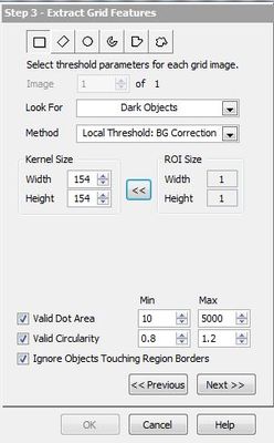
Using the thresholds the in Vision Assistant Image calibration
I would like to form images of calibration with some images of 1280 x 720 of grids that I take with a fisheye lens. Usually, when I raise Calibration training Vision Assistant interface, I have some tools really powerful local thresholding as in the screenshot above.
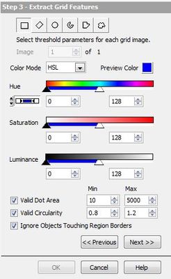
But with images that I put in now, I'm threshold options that aren't really my needs. These are shown in the screenshot below. Is it possible to manually choose the local threshold options?
Hello
You got this window because it seems that you have a 32 bit image instead of an image of grayscale 16 or 8-bit.
Convert your image into 8-bit, and you'll have the threshold parameters you need.
Hope this helps
Agress
-
I have a new 5 lb load cell, I want to replace the old one with. The former load cell had previously been calibrated to the program and was located in the drop down menu, as well as several other cells. So far all I've done is went to edit items in the menu properties ring and add in the name of load cell - I did in all references to the program. There are several references to the cell of support throughout the program, but most is a case of event "loadcell scale" that passes across the cell to the variable global-loadcell scale and a cell nationally for initialization. I have attached a manual for the program I work with (the cell for initialization is not displayed). I have never calibrated a scale before and do not know the appropriate measures, so any advice will be appreciated. I have to do something to the MAX?
as a side question what are and when do you use the stringsand values of the nodes property.
Thank you
Hello
Here are two links about calibration with our software. It is usually done through MAX and step by step instructions can be found in the links.
http://digital.NI.com/public.nsf/allkb/D22B70F72C3FB23286256F15005C2575?OpenDocument
http://zone.NI.com/DevZone/CDA/tut/p/ID/4845
As to when to use property nodes, they are used whenever you want to programmatically set some properties or attributes. For example, if you want to programmatically change the color of the text in a control that is based on what is displayed or channel indicator or resize the control or the indicator.


Maybe you are looking for
-
Using the drive 100% running 8.1 Win
Help me please, What can I do on this 100% disk usage?It is going on all the time... I added the photo, so that you can see. Sometimes he says that the system is the problem, sometimes programs like utorrent or firefox,Other times it's simply nothing
-
Need to map TV compatible Express for Satellite Pro A300
G ' Day for the gurus of Toshiba. My Toshiba Sat.Pro A 300 has a slot Express Card empty - is there a compatible TV tuner that is associated with this card - or is it Pinnacle USB or something like that? Concerning Lebog70
-
How to use the view 'cover flow' in an open file dialog box?
I often post pictures, such as screenshots, Web - like the one I included here! I always use "cover flow" as an aid to make sure that I'm the one that I want to load the download. In El Capitan, I see "cover flow" in the Finder, but not in a file ope
-
My gmail on my Macbook pro account has been hacked since I'm unable to connect to it to receive emails, but can send emails. Any ideas would be welcome.
-
HI-Grade laptop with Windows XP - Start button problem
The Start button has broken off the coast to the Interior. Is it possible to start without using this button? Thank you for your help (if you can).