USB-6259 digital input READ
Hi all
I have to admit that I am inexperienced with DAQ cards (just do simple things in the past). We just receive the NI USB-6259. The plan is to use it for many tasks. One of them is a digital signal to measure at the maximum rate. So far, I have tried ti create a task in MAX - what I've managed to achieve was to measure samples of 500-700 to 1 Mhz using N samples measurment. In order to have 1 Mhz sampling rates, I use an external clock PFI12 (output meter 0 - I put the counter to generate 20 Mhz Signal - 50ns/50ns time Time High/Low).
The thing is - it possible to obtain samples is acquired at 1 MHz with continuous mode? When I try with my current settings I get overrun error - I have tried task ru round trip - first clock generator started, then input digital. and the other way entry digital, first of all - so I guess that this overrun is not due to misuse.
In the documentation it says:
If the DAQ device receives a DI Sample Clock when the FIFO is full,
it reports an overflow error to the host software.
Is there another way to receive digital signals, where a picture lasts about 6 ms and consists of 8-bit?
Tags: NI Hardware
Similar Questions
-
Unit test, Visual Studio 2010 digital input read event
Hello!
I have problems in Visual Studio 2010, using NOR-DAQmx, but ONLY in a unit test project. I have compiled a dll that uses a DigitalChangeDetection task handler. The dll work very well in a draft standard form, but does not work in a Test project.
I used .NET Framework 4.0 with success. Tried to switch to .NET framework 3.5, but it is not possible for a test project in Visual Studio 2010.
When I start my test, it works fine until the event is raised. Once he does, the test will stop without exception or detail except the following result:
"The agent process was stopped during the execution of the test."
Nothing is caught in the trap in debugging.
Also, I get the following in the Event Viewer error message:
Log name: Application
Source: VSTTExecution
Date: 2010-12-01 11:32:31
Event ID: 0
Task category: no
Level: error
Keywords: Classic
User: n/a
Computer: xxx
Description:
The description for event ID 0 in source VSTTExecution is not found. Either the component that triggers this event is not installed on your local computer or the installation is corrupted. You can install or repair the component on the local computer.If the event is on another computer, the display information had to be saved with the event.
The following information has been included in the event:
(devenv.exe, PID 5592, walk on 73) OutOfProcessStrategy.ProcessMonitorThread: The Agent process was closed unexpectedly. will attempt to restart
the message resource is present, but the message is not in the string/message table
The event XML:
http://schemas.Microsoft.com/win/2004/08/events/event">
0
2
0
0 x 80000000000000
10312
Application
xxx
(devenv.exe, PID 5592, walk on 73) OutOfProcessStrategy.ProcessMonitorThread: The Agent process was closed unexpectedly. will attempt to restart
I understand that Visual Studio 2010 is not yet officially supported so here's my 2 questions:
-I'm the only one experiencing this problem? (Easily duplicated by taking the sample project: DotNET3.5\Digital\Read Values\ReadDigChan_ChangeDetection_Events and extract the relevent part of to put in a separate dll so that you can try to UnitTest in a project UnitTest.)
-Update on what NOR-DAQmx will rely on VS2010? (I read here: http://forums.ni.com/t5/Measurement-Studio-for-NET/Support-for-Visual-Basic-2010-NET-4-Framework/m-p... this is supposed to be before the end of the year, but no updates would be great because I could not find any information on it)
Best regards
Pierre-Luc
Hello Pierre,.
As NOR-DAQmx is not yet officially supported in Visual Studio 2010, it is not quite clear why this problem occur. At this point, the official release date has not been announced yet, however, please continue to check the updates to www.ni.com/support (drivers and updates). Thank you
Best regards
M Ali
Technical sales engineer
National Instruments
-
How to combine several digital inputs for playback?
Hi comrade Labview users.
I just started using LabView and I am very new to it. I know him understand how it works and you have something to work, but I need to be more effective.
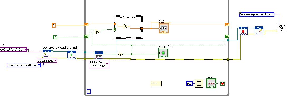
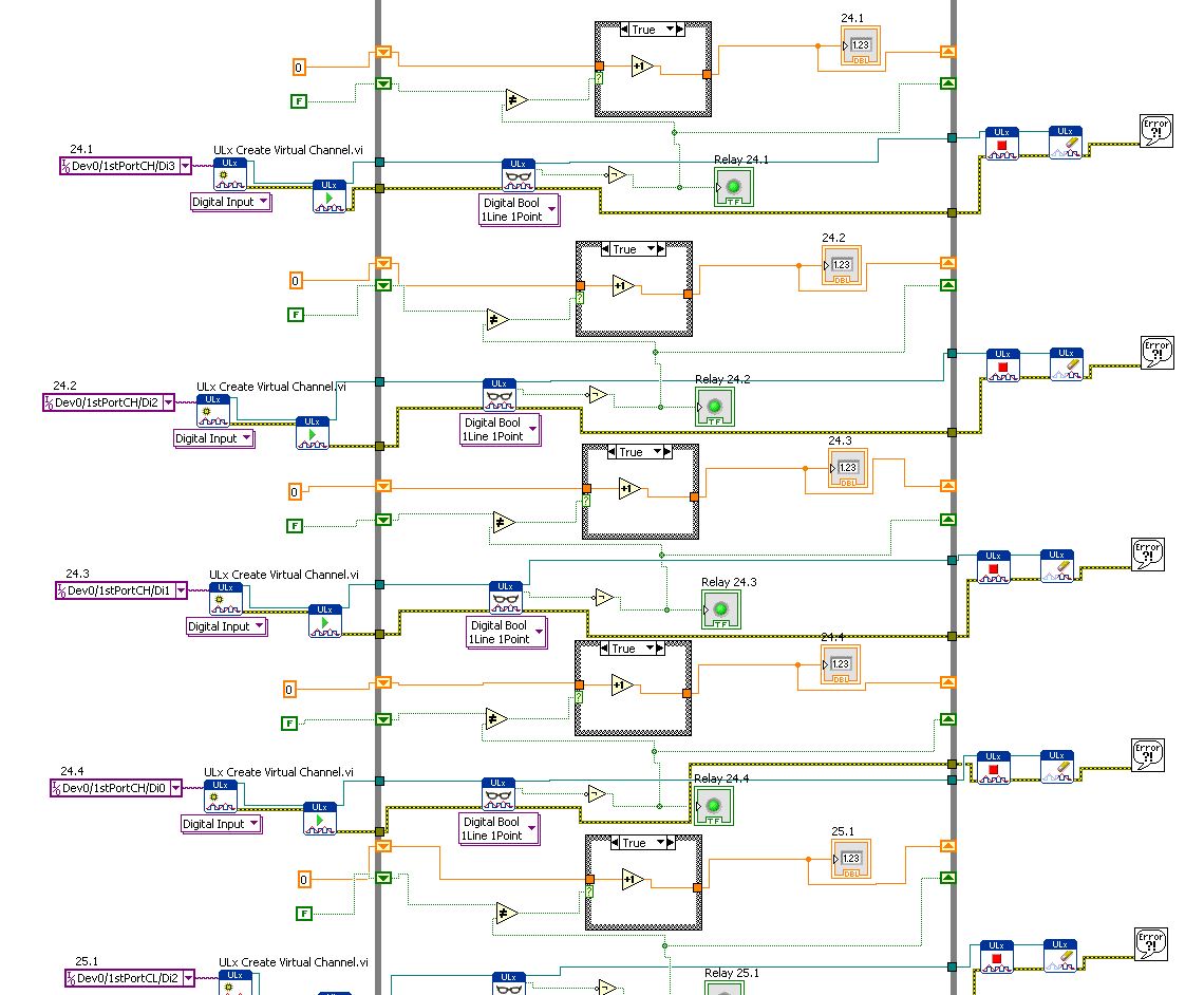
I use DIO96H - USB DAQ Measurement Computing, which includes 96 digital inputs. I use the DAQ to acquire the activations of relay and record the number of times the relays flips.
Basically, I created a digital input read and then copy & pasted 95 times... it works but I know that's not the best way to use LabView.
How can I change the digital input (Di1/1stPortA/dev0) in multiples so that it iterates through all 96 channels without copying and pasting the same pattern over and over again?
Leon
You have the correct polymorphic instance for playback? Once again, for the material OR it would be a NChan Read. There should be a similar choice if I remember correctly.
-
Reduce the period of sampling of the digital inputs of NOR-USB-6009
Hello
I need to read a line of digital input in the NI USB-6009 using NOR Express 2013 Signal box. I selected 1 sample (upon request) as acquisition mode. I need to define a smaller sampling period as 1 MS, but it gives error too short sampling period: "the current sampling period is too short. Please specify a longer sampling period. ».
I do not understand the reason for it and a way to slove this.Any help would be greatly appreciated!
Thank you!!
The 6009 doesn't have a clock that you can set for a sampling period. According to the specifications, the digital I/o is software programmed - sample on request you use now. I'm not at all familiar with SignalExpress but I don't think that you can find near a reliable khz sampling frequency on Windows or any other os non-deterministic.
-
How can I set up a digital input task to read continuous samples?
I am trying to create an exclusively digital task that will make digital readings at a rate timed by the material using a PCIe-6509. However, when I try to put the task timing as follows (which works on a PCIe-6509), I get the following error:
Requested value is not supported for this property value. The value of the property may be invalid because it is in conflict with another property.
Property: NationalInstruments.DAQmx.Timing.SampleTimingType
Required value: NationalInstruments.DAQmx.SampleTimingType.SampleClock
Possible values: NationalInstruments.DAQmx.SampleTimingType.OnDemand, NationalInstruments.DAQmx.SampleTimingType.ChangeDetection
Task name: DigitalInputTask
State code:-200077
The relevant parts of my code are:
public class DigitalInputReader: IDisposable
{
public DigitalInputReader()
{
dataReadyHandler = new System.AsyncCallback (DataReadyEventHandler);daqmxTask = new DigitalInputTask();
daqmxTask.Configure (Globals.NI);daqmxTask.Control (TaskAction.Verify);
daqmxTask.Control (TaskAction.Commit);daqmxReader = new DigitalMultiChannelReader (daqmxTask.Stream);
}public class DigitalInputTask: task
{public DigitalInputTask(): {base ("DigitalInputTask")}
public virtual void Configure (NiConfiguration niConfig)
{
<= niconfig.digitalinputs.count="" -="" 1;="">
{
String physicalChannelName = niConfig.Device + "/ port" + niConfig.DigitalInputs [i]. Port.ToString () + "/ line" + niConfig.DigitalInputs [i]. Channel.ToString ();
String nameToAssignToChannel = niConfig.DigitalInputs [i]. Name;DIChannel ch is this. DIChannels.CreateChannel (physicalChannelName, nameToAssignToChannel, ChannelLineGrouping.OneChannelForEachLine);
c. InvertLines = niConfig.DigitalInputs [i]. InvertLines;
}
var signalSource = "";
This. Timing.ConfigureSampleClock (signalSource, Globals.MachineSettings.SampleRate, SampleClockActiveEdge.Rising, SampleQuantityMode.ContinuousSamples);// Globals.MachineSettings.SamplesPerChannel);
}
}The last call to Task.Timing.ConfigureSampleClock, it's which throw errors.
Of the options available, or SampleTimingType.OnDemand or NationalInstruments.DAQmx.SampleTimingType.ChangeDetection provide the same precisely timed calls that I am familiar with the analog input interruptions.
How is it possible in a digital task? I mean, it seems that I could set up another task to do call by material for the production of a clock signal and use the ChangeDetection synchronization mode, but this seems a bit complicated for what should be easy to do. What Miss me?
Update: I thought about it. You cannot call ConfigureSampleClock when the digital input card is a device of 650 x, because these devices have any automated examples of clock. They are configured to run in mode default finite samples. You must make all sample synchronizing with these devices in the software.
Be cautious, however, because the .NET timers ensure they put any faster than their scheduled interval. In practice, they are usually 5 to 10 ms slow by tick. This means that if you want to read samples every 100 ms by sample clock, you'd end up reading all 108 ms samples. All counters based on the elapsed time and number of samples would be away after a few seconds of it.
Instead, you must do one of four things: write a doggone driver that runs in ring 0 and interfaces with the PCIe card in the required interval (i.e. on NC, not you, in practice), tolerate the inclination of the clock, use a multimedia timer as an interruption audio or video that is more likely to respond to the correct interval, or , my solution, an accurate clock allows you to set the interval of the timer. I wrote the following code to the timer:
var CorrectiveStopwatch = new System.Diagnostics.Stopwatch();

var CorrectedTimer = new System.Timers.Timer()

{
Interval = targetInterval,
AutoReset = true,
};
CorrectedTimer.Elapsed += (o, e) =>
{
var actualMilliseconds =;Adjust the next tick so that it's accurate
EG: Stopwatch says we're at 2015 ms, we should be at 2000 ms
2000 + 100 - 2015 = 85 and should trigger at the right time
var StopwatchCorrectedElapsedMilliseconds = newInterval +.
targetInterval-
CorrectiveStopwatch.ElapsedMilliseconds;If we're over 1 target interval too slow, trigger ASAP!
<=>
{
NvelIntervalle = 1;
}CorrectedTimer.Interval = NvelIntervalle;
StopwatchCorrectedElapsedMilliseconds += targetInterval;
};I hope this helps someone.
-
6259 switch digital input to output
Hi all
I use the NI PXI-6259. One of the digital inputs I want to switch to digital output, send a serial code and switch again one digital input.
Does anyone have experience with this kind of configuration change during execution of the VI program.
Thank you
Basically delete the task that he had as an input, create another task DAQmx with channel configured as output, this task, erase it, create the task with channel configured as an input.
If you need a tight with switching schedule, I wouldn't recommend this Board. You may need to set up a Council of RIO with LabVIEW FPGA.
-
I want to integrate the ANSI C sample program ReadDigPort - ExtClk.c in my own big package.
I want to use the internal clock of the BNC NI USB-6259 (.. 80 kHz 120 kHz).
In the document:
High speed M: Series Multifunction DAQ for USB - 16-bit, up to 1.25 MECH built-in BNC connectivity. / s,.
is written:
Or sample DI source clock: Any PFI, RTSI, HAVE sample or convert clock, AO, Ctr n out internal and many other signals sample clock
The digital subsystem doesn't have its own dedicated internal synchronization engine. Therefore, a sample clock must be provided another subsystem on the device or from an external source.How can I use internal clock case OR USB - 6259 BNC for the acquisition of digital data in my own big software?
With what other subsystem on the device can generate a source of the clock? How?It is possible to set a clock on an internal counter (for example ' Dev1/ctr0"):
Creates channels to generate digital impulses that define the freq and dutyCycle and adds the channel of the task that you specify with taskHandle.
DAQmxCreateCOPulseChanFreq (taskHandle, "Dev1/ctr0" units, clockName, idleState,
initialDelay, freq, the duty cycle); worksBut it is not possible to drive this internal clock to a terminal (for example "/ PFI0/Dev1"):
DAQmxErrChk (DAQmxCreateCOPulseChanFreq (taskHandle, "/ PFI0/Dev1", clockName, units, idleState, '))
initialDelay, freq, the duty cycle); does not work: error DAQmx: measurements: type I/O of the physical channel does not match the type of I/O required for the virtual channel you create. Name of the physical channel: PFI0. Name of the virtual channel: clockThe sample clock source can be derived from an external terminal (for example "/ PFI0/Dev1"):
Sets the source of the sample clock, the sample clock rate and the number of samples to acquire or generate.
DAQmxCfgSampClkTiming (taskHandle, "/ PFI0/Dev1", maximumExpectedSamplingRate, DAQmx_Val_Rising, ")
DAQmx_Val_ContSamps, bufferSize); works. Acquire or generate samples until you stop the taskBut it is not possible to derive the internal counter of the clock (for example ' Dev1/ctr0"):
DAQmxCfgSampClkTiming (taskHandle, "Dev1/ctr0", maximumExpectedSamplingRate, DAQmx_Val_Rising,
DAQmx_Val_ContSamps, bufferSize); does not work. Error: Acquire or generate samples until you stop the task: make sure that the name of the terminal is valid for the specified device. See Measurement & Automation explore valid names of terminals. Property: Property of DAQmx_SampClk_Src: DAQmx_SampClk_ActiveEdgeSource device: Terminal Source Dev1: Dev1/ctr0Hi datafriend,
using what it says is correct:
Or sample DI source clock: Any PFI, RTSI, HAVE sample or convert clock, AO, Ctr n out internal and many other signals sample clock
The digital subsystem doesn't have its own dedicated internal synchronization engine. Therefore, a sample clock must be provided another subsystem on the device or from an external source.This means that if you do not use an external signal as clock you can use the sample clock to HAVE it on board or at the output of the internal counter.
There are also 2 ANSI C examples in this regard:
http://zone.NI.com/DevZone/CDA/EPD/p/ID/4485
http://zone.NI.com/DevZone/CDA/EPD/p/ID/4488
So in both cases you have to use a fictitious task you need only for the generation of the internal clock (HAVE or CTR)
-
A voltage divider will be enough to read a 28V pulse in NOR-6251 digital input ports?
Hi all
I am a scientist life sciences that attempts to read a 28V 4.2mA pulse signal sent from my operative box animals in my NOR-6251.
Sounds like a voltage divider should do the job. But I would be aware of anything else that my card OR not to burn? And should I be concerned about the current entry in the map OR?
Thanks for your help!
Hello
Research on page 7 and 8 of the Datasheet of NOR-6251 , it shows that the maximum voltage is 5.25V, so use a voltage divider to make 28V up to 5V and you should have no problem providing you can guarantee your 28V source will always be to 28V or less and your resistances are fairly accurate. Under no circumstances should provide you more 5.25V to the digital input.
The only concern you have on current is that the resistance divider is not affected by the impedance of the digital input which is little likely (datasheet says max 250uA), so if you use resistors around the range of 5 to 50 k, you should be fine. Also, be sure your part of wiring resistance as if she had the wrong way, you will have a great chance to break the map!
I hope this helps!
-
Question of the digital input USB-6009
Hello
I use USB-6009. I have problem in Input.I digital did not connect anything on all channels. But all of the DI/O channels generate 5 volts. And I tested the DI/operating system in the Test Panel also. All digital inputs are high. How I use it? Please suggest me the solution.
You're the one who said it was generating 5V. And I said that a fine should be detected as a logic one. Connect a gnd input.
When it starts, all of the default value of I/O at the entrances.
-
I work in can bus monitoring and I have a box NI USB-6259. is it possible to read data with NI USB-6259 CanBus?
Thank you very much..
-
NI USB - 6259 BNC DAQ: analog input signal cross on the question
Hello
I use the NI USB-6259 BNC DAQ unit to acquire a four-channel analog signal, and I'm having a problem with a signal that affect others. The circuit, I am running is:
I have a wire connected to a battery (two AA batteries at ~1.5V), which then feeds the signal cable to a BNC cable, which feeds an analog BNC of data acquisition channel. The field of NBC feeds to another wire, which is attached to a conductive plate. The idea is this: when I touch the wire connected to the battery for the metal plate, I complete the circuit and thus get a binary not anything at all about 3V. When I tested with an osciloscope using two channels (each earth connection to the metal plate) I get independent steps whenever I touch any of the sons of the respective batteries to the metal plate (i.e. it works as expected). However, when I use it with data acquisition, whenever I touch a wire, I get a response in all other channels (3 others), even if their respective sons does not touch the metal plate.
No one knows why this happens, and how I might be able to stop this 'cross-talk '?
Thank you
Veritas
I see, and you're right. This request will have trouble with crosstalk. Luckily the ground channel thing should help you.
Configure your DAQ to collect twice as many channels as you need. Connect your wires in the odd channels and short circuit (ground) the entries of those even.
Now when you scan the channels it will always technically crosstalk, but it will come from a channel to the ground so that there will be nothing to interfere with your measurements.
At least that's the theory.

-
Hello
After reading everything that specifications and manuals, I decided to ask a general question.
In the data sheets, user guides I've read, in general, there are two warnings for DIO:
-Do not connect the outputs digital circuits which operates above the limits.
-Do not drive the line with tensions outside its operating range.
Generally speaking they tell me I need to know when dealing with output and voltage when dealing with entries. So I have this question, can I wire a power supply for digital inputs directly without exceeding its "beach of normal operation and without any protection circuit? In fact, my feelings, this is not possible. But why certain documents produced clearly mention that the impedance internal inputs while that of others is not clear those? How can I determine if I can connect a signal directly to an entry (for example USB-6525 indicates a current limiter circuit, but I don't see a clear explanation in the datasheet USB-6251)?
As long as the input voltages are within specified limits, no damage will be the DAQ hardware. Logic devices often have two lines of non overlapping input, one for low input and high input. If the input voltage lies between the beaches, the performance of the device can be unpredictable. Also, check your power supply to make sure that this doesn't not exceeding when turned on or off as that could exceed the DAQ limit.
Lynn
-
NI USB-6501 digital output problem
Hello
I use DASYLab v.11 and I'm working on an interface with the NI USB-6501 where I'm putting a digital high on four ports.
With the module "NOR-DAQmx - digital input", I managed to read the digital inputs of the ' NI USB-6501 ".»
It's only the "NOR-DAQmx - digital output" I can't go to work.
Using 'NI MAX' of NOR I have easily can emmit my four LEDs in the way of my High/Low ports.
But not with DASYLab. When you use DASYLab tension on the ports remains unchanged.
Now, I have a switch module, generating 5/0, directly connected to the digital output module, which is assigned to my four output ports for my task.
I also tried with a module of relay between the two without success. I also tried to use 1.5 above instead of 5 without success.
I use the option 'Bus (0/5 supply) for the module "Digital output".
"NI Max", I configured the ports as "active drive.
Any suggestion of what I might be missing?
Thank you
Martin
Hmm, four ports, or four lines?
A port consists of eight lines. Each line can control an LED (ON / OFF ~ 0/5V).
If you have created a task to dig-out to control a port, 5V to this port sending sets all lines of this port to 'high '.
You need to 255 for each line one too high port (at the bit level: 128 + 64 + 32 + 16 + 8 + 4 + 2 + 1).<- eight="">
Or, you can create a dig out tasks to control four lines of a specific port.
Four lanes of the EEG DAQmx DigOut module.
Each of the channels of the modul will feed a single line of the task/device.
Four switches will then turn the lights, or turn off.
Make sure, that the 'bitposition' is the number of correct line (see picture).
-
Hello world
I use an NI USB-6501 and I'm trying to understand how to read the entries.
I used this card to generate output using the example vi write Chan digging, it works fine.
Now, I'm trying to use the example of reading dig Chan vi to read an input voltage. But it seems that, by default, the map reads 5V (a 1 logic) as entered on each pins, even if nothing is connected to them. I tried to connect the output to the input, use a relay to see if it detects a change in the entry, if we send a voltage or not, but it changed nothing. It still reads 5V anything.
Can someone help me understand how to be able to read an entry? This problem has happened to someone else?
Thanks in advance.
Frédéric
If you dig through the data sheet, you will see that there is a 4.7kOhm shoot all digital inputs. So with the floating inputs you will get a high (logic 1).
As Dennis have already said, wire your digital output directly into your digital input. So everything that you set the output that you will read on the entry. I don't know what you do with a relay.
-
Create two independent signals and a pulse train with NI USB-6259
Hi all
I'm new to the forum, I searched but I've found no info about it.
I have recently set up a vi that is able to generate from an NI USB-6259 case two different signals in frequency, amplitude and phase (see attachment).
To do this with each cycle of the memory buffer size is changed accordingly for frequencies in order to see a whole number of periods and, thus, having not leak in the generation (or breaks).
Now, I would like to generate a pulse train at a frequency that is an integer multiple of the frequency of the input signal (not the 50 Hz one).
The resulting frequency of the pulse train could be changed on the fly (or at least be updated at each new round of vi).
I'm stuck because I have already said that two analog output channels and I want the pulse train so that a digital camera for my Board (channel PFI) output, you have any ideas?
Thank you very much
Alberto
PS. the vi is "program generazione.vi" but you must first install "signal.vi production".
Hello
It is a simple .vi which generates a configurable, buffered pulse train dynamically. I also want to let you know that with this type of advice (DAQ), it is impossible to update the output in real time. You must be careful because the time between you use "DAQmx Write" and the output effective physical change not IS NOT FIXED.Kind regards
Matteo
Maybe you are looking for
-
Satellite L750 - no sound on the speaker or headphones - static
Hello I have problems with the sound in my laptop for a few months. At first I thought that he would go away with updated drivers, which makes certain the alternatives system restore or changing audio device drivers high definition of Win 7, but I ca
-
I recently bought a NB305 for professional use (need for portability and battery life) I have a question about. I would like to install a 128 GB Kingston SSDNow V-Series Disc both improve performance and independence. My questions are, will this work
-
Qosmio F750 - 10L - how to look at pictures in 3D?
I bought this laptop 3D 'Glass-Free' only because I wanted to look at my pictures 3D in my travels.But it seems not work with any of my 3D-viewers!I does not work even with the Nvidia - 3D - Photo Viewer?What I really need to use glasses Anaglyphs if
-
I can't reinstall new update
-
How to rotate video in windows media player
Running XP svp3 Windows Media Player. In a file vid, first few images are OK then video rotates 90 degrees. In another vid file, everything is rotated 90 degrees.