using c#, AnalogWaveform. GetRawData() vs. Samples
HI - simple question:
Suppose I have some data in the form AnalogWaveform
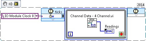
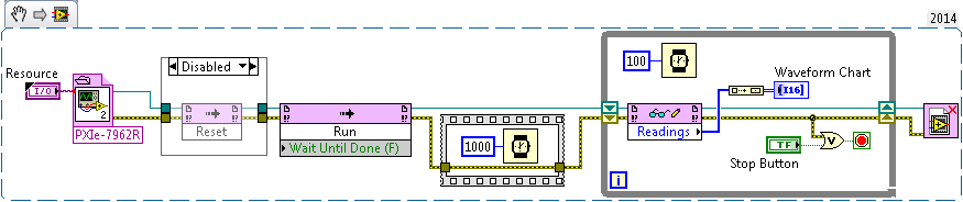
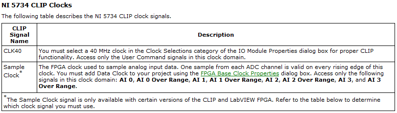
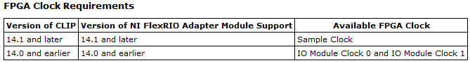
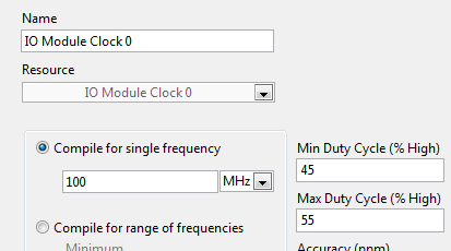
and I want to write to the disk (without wasting time, as I work on the continuous acquisition in real time) What is the difference between AnalogWaveform.Samples and AnalogWaveform.GetRawData ()? What are the advantages/disadvantages? Thank you! Chicago_Joe, The raw data are the data before the scaling has been applied, so that the samples will already have been converted to real tensions. Thus, for the purposes of data entry, it is probably more useful save samples. However, it is possible to manually convert raw data to tensions. Here is a sample program (in LabVIEW and C++, but the same thing could be done in c#) that takes the raw data and converts it. In addition, if you want to learn more about the raw data, here is an article of knowledge that talks on this subject. It refers specifically to the DAQmx functions in LabVIEW, but the same thing applies when you use DAQmx with c#. -Christina Tags: NI Software I work for a company that produces and transforms electric parts. We strive to get in remission at nine of the ECU, experiences, Instrument clusters etc. I'm trying to learn how to use LabVIEW to write commands and read the data on the CAN bus. I have downloaded the NI-CAN driver. I am currently 'play' with the same reception Port.VI show in the basic frame of the finder example API folder OR. I am not able to send the number in the data to write the table that it be read by the ncReadNet Mult .vi. When I put the parameter to 'Pending entries reading' the ncGetAttr.vi returns a 0 to indicate that there are no frames to read. As a result, the Mult.vi ncReadNet does not run. I don't have any connected equipment, I use the virtual CAN channel CAN256. Is this the reason why I can't get data frames in my queue for the Mult.vi ncReadNet to read? When you use the NI-CAN Transmit sample receive the same Harbor; can a virtual CAN channel (RCA or 257) be used? CAN carry 256 and 257 are connected to eachother through software. When you write about 256, you can read the data on 257 and vice versa. I think the example you mention is a writing and reading on the same port, but what you want is to probably to make a copy of this VI, in order to run two at once, where it opens 256 and the other opens 257. Then, when you write one that you will see on the other. I think you might be able to use the test panel CAN too read an and use the example of the other. In the resolution of the technical document ADC PCI 6221 = 16 bits at 250 kech. / s means I use all channels, then each sample channel = 15,625 kech. / S ?. Yes. How do you use the freqout as the sample clock to write data on the of 6224 PCI Using PCI-6224, I try currently to export data using the freqout as a reference clock sample to a digital output channel. I plug the scope to see the clock on the freqout PIN. However, the data seem to be missing. How can I output the data correctly using the reference for timing? What am I missing that connects the two signals together? Any help would be greatly appreciated. I am writing this code in MS VS C++ and here's what I've done so far: I think that the original code was operational. However, given that the data transmission has been set to finished, I had a hard time to visualize the data on my scope. By changing the value of DAQmx_Val_FiniteSamps to DAQmx_Val_ContSamps, I could easily see the data. My mistake. I'm still learning here. Thanks for the time. Creating an Application Launcher using the homescreen of the sample in Windows Embedded Hello I had made a request and I have this application must be run on windows embedded 7 homescreen based startup (application launcher)! As I need to customize the home screen Windows Embedded to be my application then and another under customization Thank you Hello Your question of Windows 7 is more complex than what is generally answered in the Microsoft Answers forums. Appropriate in the MSDN forums. Please post your question in the MSDN forums. You can follow the link below to ask your question: http://social.msdn.Microsoft.com/forums/en-us/category/windowsdesktopdev I hope that helps! AI sample clock using to Trigger counter samples My basic question is: the ai\SampleClock signal is active only during the execution of a task of analog input? The details are: I have a multifunction data acquisition card series X PCIe-6321. It is controlling an SCXI chassis and has a module SCXI-1180 and SCXI-1302, so I can control the analog inputs of the chassis but also access to the meter 4 on the map. My application requires that I use all 4 meters to measure a frequency input signal and synchronize the samples for the analog input signals. I created 5 tasks, 1 for AI and 1 for each counter. I'm using LabVIEW 8.6.1 with the latest NOR-DAQ drivers on and the operating system 64-bit Vista 1 are there drivers or hardware restrictions that cause this solution does not work? 2. can I use the ai\SampleClock as sample clock of entry for each task frequency? If I do this the beginning of sampling will be synchronized? I.e. If I each task frequency first starts, they will wait until that task to HAVE it is started before you start sampling? 3. If this does not work, do I need to send the sample clock of the task of the AI to a line PFI (PFI1) and then use it as the special frequency sample clock input? I used to do option 3 when the synchronization of two cards in PXI chassis and use only the beginning of the task of the software instead of synchronization on a digital departure, given that the sample clock will control samples anyway. I need to know if the same behavior works with the above scenario. Thank you Bob Prolucid Technolgies Inc. Hi Bob, I can confirm that the AI/SampleClock is available only during the execution of the task to HAVE it. As far as other issues go: 1. you must provide more information on what you seek to do exactly, but there is no problem with the clock of the task of analog input sampling to be used with routing counters. I had read through the section of the X series operating manual which deals with the measures of frequency clocked at sample (see page 7-16) for more information about what really happens during this configuration to make sure that it suits your needs. The frequency of the signal to be measured must be at least two times faster than the sample of your task clock to HAVE. 2. you can indeed pass the signal on all four tasks at the same time (you can check the page peripheral routes in MAX to ensure the routing restrictions). Sampling will be synchronized four counters are started before the task to HAVE it, but counters will be armed at different times unless you configure a trigger to begin arms (see page 7-45 series X operating instructions). I would consider using the AI/StartTrigger if you want to do. The effect of not to arm the counters at the same time would be a different number of periods on average on each counter for the first sample (assuming an average is enabled). Maybe it's not a major concern, but I just wanted to point out. 3. the itineraries are available inside the Board of directors so external routing is not necessary, you can simply specify to use the sample clock of the AI for each meter clock and roads will be done for you. If you want to export the signal on a PFI line and new route on another line PFI, this option is also available for you, but shouldn't be necessary. I hope this helps you get started. I'll make sure to take a look at Chapter 7 of the X series user manual, if you have a chance as he described how all configurations of meter of working more in detail. If you have related questions do not hesitate to post in return. Best regards John Understand how to set up and use a sample FlexRIO clock Hello Following this discussion on inputs glitching, I learned that I need to use the area of the sampling clock to read nodes to HAVE it in my 5734 OR. So I right click 'FPGA Target'-> "New FPGA Base Clock" and selected "IO Module clock 0". In general, I followed the instructions at http://www.ni.com/pdf/manuals/375653a.pdf Issues related to the: Hi FKSH, You are right that you must Access your e/s on the 5734 NOR in the area of sample clock: (this information is by using LabVIEW for the CLIP of 5734 OR) It is a clock Module e/s 0 or sample clock based on your version of the FlexRIO driver you have installed. Based on your statements, looks that you use LabVIEW 2014, so be sure to have FlexRIO 14.0 or FlexRIO installed 14.1. If you have FlexRIO 14.0 or earlier, the sample clock will be IO Module clock 0. If you have FlexRIO 14.1 or later, it will be the sample clock: (also of the documentation NOR 5734 CLIP in help) The only support for sampling rate is 120 MHz, unless you use an external clock CLK in and it must be between 50 and 120 MHz (see page 9 of the Manual). If you wish to purchase to 10 MHz, the best thing to do would be to sample the e/s to 120 MHz and then decimate the data by a factor of 12 (keep all 12 data points only and throw out the rest). Regarding the FIDL, I'm guessing that you're referring to the configuration in the properties of the clock: This configuration is not actually change the frequency of the clock. The compiler uses this value so that the logic can operate at the specified frequency, but the real clock is provided elsewhere (in this case, the FAM).
Finally, I saw error-61046 occurs more often because of the configuration of the internal clock. Make sure you use the clock on the right as the only cycle timed loop source as I mentioned above. In general, I do not recommend write directly on a 120 MHz indicator, as there are a lot of other logic that needs to be done in order to update the indicator. The data are sent to a domain different clock under the hood, so you can actually update the data and I suspect that there are some conflicts with the clocks. You also lose data as the host won't be able to read all the data before it gets crushed. Instead, I would use DMA FIFOs if you need all the data you acquire or to send the data to a different loop which will be responsible for the update of the indicator in a slower clock domain.
In general, I recommend always that the start-up of the examples in the Finder as a good place to check if the equipment works properly and as a reference for the correct configuration. Once you compile the code, you should be able to run it natively to acquire some data. "" "These examples will be under input and output hardware" FlexRIO "Modules e/s ' NI 573 X ' NI 5734. Best regards Reading and samples the sampling frequency using a fast external clock Hello I use an NI USB-6212 box to launch a search engine for combustion. I have a pressure sensor in the head and a wheel on the crankshaft. I use the beats A Quad channel of the rotary encoder as a sample external to the pressure with the sample clock. The idea is that I want almost the same number of points in each trace of pressure so that it is easy to average together. I seem to be able to do this at low speed, but I'm having issues at high speed. Can someone tell me what I should have my sampling rate and samples to read together and how it effects my sampling when using an external clock? Samples per channel will affect the size of buffer and that matters? When I was high (10-100 kHz and about 1/10 * rate for samples to read) it barely read but as I put the lowest and lowest he read faster. Play with the settings a bit seem to affect how well it samples at different speeds. The engine is running at 3600 rpm and my encoder puts out 2500 pulses per turn on one channel, I'm looking at a frequency of 150 kHz effective sampling. However I didn't sample program with the engine operating at full throttle. I hung on the output of the encoder up to a scope and reads very well. Are there opportunities the filter counter that I see in the manual of 621 x is enabled inadvertently? Thank you Xander Xander18, I suggest you move your screws initialization outside the while loop, as well as your narrow DAQmx VI. On my side, it looks like a new task is performed for each loop, which takes time. That a try and let me know how it goes. Hello! So I had a quick question- If I wanted to use a kit of drum samples, how I'll go on using that at the hearing? I can't seem to find a setting of MIDI instrument or sequencer like other DAWs, I worked with. Any help would be appreciated; Thank you! Hearing is not a built in abilities noon at all - it majors is an audio editor. (An earlier version of hearing... Aa3... had a very simple MIDI implementation, but this has been removed from future versions as necessary development time to make it a complete MIDI sequencer would have taken away from more important things.) AnalogWaveform example of tracing I'm looking for a few examples on how to view the analogwaveform of data type on a waveform graph. I looked at examples of national Instruments\MeasurementStudioVS2005\DotNET\Examples\Application, but none of them use the analogwaveform data type. The examples in this dir much use a simple example where the data in an array of double. Are there examples of how to work with the type of analogwaveform? Hello There are several examples in the The trick that I use to find if there is an example that incorporates some I hope this helps! Best regards Can I get a license for my track finished for use of Film/TV? Hi, I would like someone from Apple please answer this question for me, I think I asked before when it bought the software but cannot find the transcript. If I create a song/track in Logic Pro X mainly using sound libraries provided as part of the program, can I get a license my track finished out for TV/film use without any legal return of Apple? Thank you Yes, you are ready to go! You just can't take a drum loop and resell it as a drum loop - it must be in something other than assets distributed by apple. You can take this drum loop, use it in a movie or a song and it is free of rights. You can't buy a brick and sell like a brick - but you can buy a brick, use it in a home and sell the House. (How's this for a silly analogy) Learn more about the ways in which you are allowed to use the free content provided with Logic Pro X and MainStage 3. The State of license agreements for software Logic Pro X and MainStage 3: The use of DAQmxWriteDigitalScalarU32 for write channels share the same ports? Hello I have a USB-6509 and NOR-DAQmx installed 15.5.1. Using the ANSI c api. Is it possible to create several independent channels that use different lines of the same port? DAQmxCreateTask("",&th1) DAQmxCreateDOChan(th1,"Dev1/line0:4","",DAQmx_Val_ChanForAllLines) DAQmxStartTask (th1) DAQmxCreateTask("",&th2) DAQmxCreateDOChan(th2,"Dev1/line5:9","",DAQmx_Val_ChanForAllLines) DAQmxStartTask (th2) .... and repeat for the following strings: Dev1 / line0:4 So I can use DAQmxWriteDigitalScalarU32 to write to each task independently? for example: DAQmxWriteDigitalScalarU32 (th1, 1, 10, 0 x 1, NULL) DAQmxWriteDigitalScalarU32 (th2, 1, 10, 0 x 2, NULL) DAQmxWriteDigitalScalarU32 (th3, 1, 10, 0 x 3, NULL) ... DAQmxWriteDigitalScalarU32 (th6, 1, 10, 0 x 6, NULL) These tasks will interfere with each other because they use the same port, but are assigned different lines? If this isn't the case, I bits to the data, if the task/channel does not start at the Px.0 line? Thank you! Yes, as long as you use the same line on different channels, they must not interfere with each other for this reason, you can create a channel by line if you wish The reference to using the DAQmxWriteDigitalScalarU32 function: http://zone.NI.com/reference/en-XX/help/370471AC-01/daqmxcfunc/daqmxwritedigitalscalaru32/ So yes, the DAQmxWriteDigitalScalarU32 can write on each task independently Continued use of digital dashboard to stop a generation pulse train Hello I need to generate a train of pulses for a period of time. However, this period is variable, and because of that I can't Use the finite number of samples. The pulse train must be output depending on the State of the digital I/o. When the line output goes high, must be output of the pulse train. and when he goes down the pulse train should be stopped. I use a USB-6212, but is already using one of the available counters for the measurement of pulse width. I tried to do a AND logic with the pulse train and line activate, but due to the execution time of vi this solution modifies the pulse train frequency, which is not acceptable. Thanks in advance, Mariana. Hi Marianne,. Your previous message mentioned "line in/out" (in the singular) and "enable line" (in the singular), isn't "the i/o lines" (in the plural). Are the two edges on the same line in/out? Or are they on separate i/o lines (for example, climbing on PFI0, falling on PFI1)? Can you clarify your needs? If the fronts and sides come from the same line of output, then a relaxing break seems to do what you want: cause the meter generate impulses while the input/output line is high and cause the meter to stop while the input/output line is low. However, if you start the job, while the input/output line is high, it will immediately start out impulses. If you want to wait the first front line input/output to generate impulses, you can use a trigger 'start of arms' (which is just below "break" in the node property). When the trigger 'arms beginning' arrives, the meter will be armed, and therefore, the task uses the break to determine when to generate impulses. Using pause and start the same counter task returns error-200146, "put in Pause and start triggers cannot be active in this task," but using break and triggers 'arms beginning' in the same task of counter should be correct. If you want to increase the edges of PFI0 to start the meter and the fall of the edges of PFI1 to stop the meter, which is more complicated and it will take thought additional (and possibly additional hardware). Brad fast sampling rate question... Hello I use USB-6009 and max sampling rate is about 48 K samples/s according to the specification... Question 1. 48 K samples/s means... only when you receive 1 analog input? If I have 2 analog inputs then forge would be just half of the 48K? Question 2. using the daq assistant. I would like to get about 50 samples between 10ms If I do the math I get 5 K samples/s, which is enough for me However, I played with samples to read and throughout the day, the sampling rate, do not get this rate... (I'm outputing in file with LVM) I searched on the sampling frequency, and people here said samples read and sample rate do not havea correlation... but I see clearly that they are relevant. When I change a setting I get a different number of acquisition... I do N smaples. Please help:) Q1. Yes, except that the switching of channels takes awhile so the net price per channel is slightly less than half the rate of single channel. The USB-6009 specification document does not indicate what is the switching time. You should be able to get 5 kHz on both channels. 20 kHz might be close to the upper limit, but that's just a guess. Q2. The DAQ Assistant is often not the best choice for maximum performance. I do not have the DAQ Assistant, so I can't be more specific. If you get the data as an array of DBL, rather than dynamic data type, it can be recorded directly, without conversion. The other thing that can make a big difference is a loop two architecture of producer/consumer. This allows the acquisition of data and save it to the file to run it at different speeds so that each can be optimized separately. If you are trying to acquire 50 ms of data at a time and then, he writes to the file, you write to the file twenty times per second. The first time, the operating system must reallocate some file space or do something else what delays write the file, your timing loop is disrupted. Lynn Hello: I use the card PCI-6602 and am a bit new to the use of timer/counters. I use the Commission to measure the position of a quadrature encoder. I would use the time base internal 80 Mhz the map of 6602, but examples of LabVIEW will not allow that. In the example, he States: 2. call the DAQmx Schedule VI (sample clock) to configure settings of clock synchronization external sample Mode Sample and sample clock Source. The sample clock Source will determine when a sample will be inserted into the buffer. The 100 kHz, 20 MHz and 80 MHz time bases can serve as the sample clock Source. The Edge parameter can be used to determine when a sample is taken. Is it possible to use the database internal time for my application? I have attached the example vi that I use. Thank you. Pat Hi, Pat. The rate determines how fast the samples are acquired and put on the material buffer. This value depends on the basis of time, which is specified by the source of the VI DAQmx calendar entry. The default source on the PCI-6602 map is the on-board clock (80 MHz). The rate must be a divisor of the source. For example, 80 MHz, 40 MHz, 20 MHz, 10 MHz,..., would be acceptable values for the entry rate. So the answer to your question would be to remove the entry from the source and ensure that the rate is a factor of the source. Leaving this entry unwired will use the clock shipped by default of the unit, as shown in the screenshot below: I hope this helps. Tecra M11: How is 1080i/p of DisplayPort? I hung my Tecra M11 via one-adapter mini DisplayPort to HDMI on my TV, but it seems that the best he can do is 800 x 600! (WIndows XP) How can I get 1920 x 1080 on this laptop? Remove drivers Intel?Add new drivers Intel?Patch from Microsoft? Is it po How will I know if my Touchsmart 300-1210uk computer has Bluetooth? I'm trying to connect my new phone which can connect only through Bluetooth, but neither the PC or Mobile can find each other. I have the connectivity and the visibiity lit on the mobile but cannot work on the PC. The word Bluetooth is written on the When released the switchable graphics drivers for dv6-6004sa? I was given to understand that all laptop computers manufactured after Jan 2011 would have drivers of Windows 8. This laptop has switchable HD4250/HD6470 GPUs.The AMD former driver for Win Iexplore.exe - USE HIGH CPU - 50% (dual processor) - Windows Vista Home Premium Help, please! My HP dv9000 is slow. PLEASE LET ME KNOW WHAT INFO YOU NEED ME! In the Task Manager, under the terms of 'process', it indicates that there are FOUR INSTANCES of internet explorer running, but I only have one window open (with a tab). This monitor works fine but is detected by the generic as 'PNP monitor' Device Manager. My video card is detected correctly. I am running Windows 7 Pro 64-bit. It also shows that Asus VS247 in devices and printers. I checked the Asus support and theySimilar Questions
int32 error=0;
TaskHandle taskHandle=0;
TaskHandle taskHandleFRQ=0;
char errBuff[2048]={'\0'};
uInt8 data[8]={1,0,1,1,1,0,1,0};
/*********************************************/
// DAQmx Configure Clock
/*********************************************/
DAQmxErrChk (DAQmxCreateTask("",&taskHandleFRQ));
DAQmxErrChk (DAQmxCreateCOPulseChanFreq(taskHandleFRQ,"Dev2/freqout","",DAQmx_Val_Hz/*Units*/,DAQmx_Val_Low/*IdleState*/,0/*Delay*/,10000/*Freq*/,0.5/*DutyCycle*/));
DAQmxErrChk (DAQmxCfgImplicitTiming(taskHandleFRQ,DAQmx_Val_ContSamps,8));
/*********************************************/
// DAQmx Configure Digital Output
/*********************************************/
DAQmxErrChk (DAQmxCreateTask("",&taskHandle));
DAQmxErrChk (DAQmxCreateDOChan(taskHandle,"Dev2/port0/line0","",DAQmx_Val_ChanPerLine));
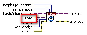
DAQmxErrChk (DAQmxCfgSampClkTiming(taskHandle,"/Dev2/PFI14",10000,DAQmx_Val_Rising,DAQmx_Val_FiniteSamps,8));
/*********************************************/
// DAQmx Write Code
/*********************************************/
DAQmxErrChk (DAQmxWriteDigitalLines(taskHandle,8,0,10.0,DAQmx_Val_GroupByChannel,data,NULL,NULL));
/*********************************************/
// DAQmx Start Code
/*********************************************/
DAQmxErrChk (DAQmxStartTask(taskHandleFRQ));
DAQmxErrChk (DAQmxStartTask(taskHandle));
Steve_InMA,
example in the UI\WindowsForms\Graph Directory uses this data type as well as a part of the DAQmxWithUI
examples such as AnalogDataFileProcessor, GlobalContinuousAO, SpectrumAnalyzer,
etc.
data type or function is to do a Ctrl + F on the samples directory,
a search using "all files and folders", and then type in the
name of the function or data type in the 'A word or an expression in the.
the file' field. It works really well.Logic Pro X and MainStage 3:
Using free content included in
Commercial works
The Apple software may contain sample content including but not limited to the work, audio files, audio loops, built-in sound files, graphics, images, impulse responses, photographs, samples, sound games, sound settings, video files or similar assets ("sample content"). This sample content is owned by Apple and/or its licensors and is protected by applicable intellectual property and other laws, including but not limited to copyright. Except as otherwise provided, sample all the content included in the Apple software can be used on a basic free to create your own soundtracks for your film projects, video, audio and. You may broadcast and/or distribute your own tapes created using the contents of the sample; However, individual active content sample not commercially or otherwise distributable on a standalone basis, nor may they be repackaged in whole or in part as audio samples, clipart, music, sound effects, sound files, sound libraries, animation stock or similar assets.
Dev1 / line5:9
Dev1 / line10:14
Dev1 / line15:19
Dev1 / line24:28
Dev1 / line29:33
"A sample of the integer unsigned 32-bit unique, wrote to a task that contains a single digital output channel. "Use this format for devices with up to 32 lines per port.
Maybe you are looking for