Using controls IMAQ Image in steps of LabVIEW
Hi guys
So far, I used TestStand 4.0 with LabVIEW 8.5 and Vision Development Module 8.5 with no problems. Recently, I've updated to LV 8.6 and 8.6 VDM. I started having weird problems when using LabVIEW steps with input/output containing IMAQ Image controls. When I try to click on such an approach in the seq editor or try to insert a new step in the sequence, the initialization step takes a long time (a few tens of seconds) or completely freezes. I also tried to upgrade TS to version 4.1, but no difference. Also, my colleague experiences very similar symptoms on the same software configuration. The only difference is that on his machine, it takes only a few seconds when you click on the step in the vision. However, the steps containing only not an IMAQ Image control behave normally, i.e. you will not encounter any "time initialization" when clicking on it in the sequence.
To illustrate, I enclose a simple VI containing nothing more than a single Image IMAQ control. If you don't link to the connector pane, the VI works fine when it is inserted in a time of TS. If the Image IMAQ control is bound to the connector pane, TS freezes when inserting such an approach.
Vladimir
The problem that causes this problem has been identified. More information is available here: with TestStand and LabVIEW 8.6 known compatibility issues
Tags: NI Software
Similar Questions
-
'Create a Subvi' movements labels (LV2013) IMAQ image controls
Hello
I noticed a strange behavior in LV2013 (x 64 and x 86) what SubVIs creation from a selection containing Image IMAQ son:
The labels out of place of obtained characteristics Subvi on IMAQ controls/indicators, see the illustration below.
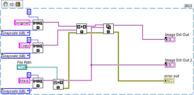
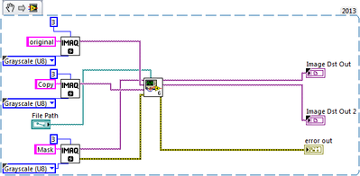
This VI
is impaired by creating a Subvi for copying and masking as follows
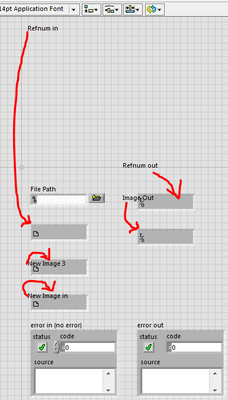
The Subvi created has a façade that result that looks like this:
All labels on IMAQ orders/lights are completely irrelevant. I couldn't understand, what appears to be a function of the new position of the label. In any case, it is quite annoying, because labels sometimes moving out of the main visible portion of the public Service and you have to go and look for them (through the window). -You must identify all the labels with the command/indicator to put everything back in place.
One of my colleagues has confirmed this behavior on a different windows PC, using the same version of LV in x 64 and the same version of Windows 7 Pro)
Of course, a simple method of MoveToDefaultLocation on all PS elements cause they go where they are expected to be, but how tedious... I remember not such behaviour in LV2011 where I used 'Create Subvi' loads of times with IMAQ Vision functions.
I'd be happy if someone such color in it. Thank you very much.
Cleaning of façade create a Subvi is performed, but it's not explicitly change the position of the control and indicator labels. There seems to be a bug in VI server when setting the position of the refnums IMAQ. This bug is independent of the function to create a Subvi. When writing of the 'Position' of a refnum IMAQ control property, the label seems to throw himself in a weird position. I've not seen this with other types of control with other controls, their labels always remain in the same relative position when the control is moved.
I'll drop a CAR against the Position and IMAQ refnums property. In the meantime, you can use the VI attached to this post to solve the problem. Follow these steps in LabVIEW 2013 or later:
1 copy of the VI attached to the following location: [LabVIEW 20xx] \resource\plugins\CreateSubVI
2. restart LabVIEW.
Once you have done, the position of the label IMAQ refnum to correct every time that you perform an operation to create a Subvi.
-
I have a few qeustions about IMAQ images and control charts
First qeustion is: library in the IMAQ, you have the image control how can I possibly call the "Zoom to adjust" function thanks to a button, rather than with the right click because I tried it and I can't find anywhere so that claire KING simply is sided with the nodes to invoke.
Second qeustion is: when you have a chart, how can you control the X value that you look with a numeric value that allows you to adjust the visibility graphic on some value x, for example, I make a numeric with a value of "10", I'll have the chart to access the value '10' so is it possible anyway I tried to work with some nodes of property but I get a little tangled in the web page of possibilities.
Third Qeustion is: it is a qeustion minor but I would ask anyway why is that when you change the value of a button you can change only once in the structure, and not twice because I would like to have a button when this button is true it affects the other 2 buttons true and when it is false it affects other 2 buttons false... I can only get the effect to 'true' or 'false '. To complicate things even more if I still want to be able to use the 2 buttons that are defined differently by the first button, it's just if I can automatically start and stop the two buttons at the same time.
and while I'm I also have a fourth qeustion: is there some way you can use the line tool several times in the section IMAQ image because the tool palette allows only 1 line.
This VI use you to lines... is it "IMAQ Overlay line?
Try the attached code...!
And if it is a solution to your fourth question, then it seems that all your queries are resolved...

-
use of display and IMAQ image memory
Hello
I wonder how much memory is used when updating from imaq image display.
I need to display images (512 x 512 size) acquired by a camera in real time. But I don't necessarily need show each of them so that can save me some memory. The camera runs at 50 fps and I can live with display rate 5 frames per second.
Right now my image display is updated from the buffer (updated at 50 fps) continuous (Snapshot mode off). I guess I have 3 options:
1 use the lifestyle snapshot and say explicitly on the screen to update. Whenever the display is refreshed, a copy of the image is created. But I guess that the previous copy is destroyed at the next update. If this method costs an extra copy of the image in memory.
2. create an extra copy of the image that is updated only at 5 fps and connect it to the display of the image (Snapshot mode off). I think this is equivalent to method 1, with respect to the use of the memory.
3. in the State. No additional copies of the image is stored. But the display is updated at 50 fps.
Which is more expensive, update the display 10 times faster or holding an extra image even copy of the memory size?
Thank you!
It is not really a memory problem: you have an indicator to display images. Display an image requires additional resources, but there is no continuous memory allocation! Once the resources are allocated, the use of the memory of your application will remain stable. (Otherwise, something goes wrong and need to be identified and fixed.)
-
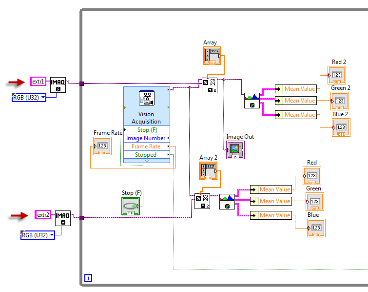
Problem using Extract IMAQ. Don't not out two different images
Hi, I am using the multiple functions of extract IMAQ for some parts of the image of the webcam, then using color extracted from function to get values of RGB. The problem is that two functions extract IMAQ give the same image on its out port. The extract of diagram of block and VI are attached below. Also, please let me know if there is a better way to do this. I need to expand this later to extract parts of the image instead of two different about 40 - 50 RGB values below.
It's happened because IMAQ Images transferred by references. You must provide images of different destination for each extraction:
Andrey.
-
Hello!
I want to know if there are and what is the installation package for use IMAQ Image.ctl including LabVIEW in 2014?
with the .exe with labview DURATION that it does not ask me to install the control so that in the development wonder
Thank you
just need to 'Common Vision 2014 resources' package is also present in the Labview Runtime
-
Hi, I'm using LabWindows/CVI 2010 with NI Vision and NOR-IMAQ libraries and map of CL 1427.
I would like to know how the Vision Development Module handles the imaqSubtract and imaqThreshold functions, are they run to the hardware or software level? I wrote my own functions of subtraction using the address of the buffer for the image and the loops but you don't you 10 Hz compared to 30 Hz with imaqSubtract VDM functions. Thank you!
FeralPhys
Yes, they are handled in software on the host computer. The 1427 Camera Link adpater does not contain an FPGA, you can use for the treatment of the physical image. You can configure the driver to search for harware database (you can do this in Max and then save the file to the camera). But that's all. All features of Vision in CVI will run on the host computer.
If you are interested in processing equipment, the PCIe 1473R can do so by using its embedded FPGA, but you need LabVIEW FPGA to do programming.
It is more complex, but can be useful in critical applications at high speed.
-Christophe
-
Store/communicate IMAQ image (binary) between the structures of the case
Hi all
I am trying to build a VI for a controlled industrial vision system and it has 2 process: first an image of calibration comes a sequence of discrete of images. After that, the user can start and stop the continuous controlled process of machine vision. This process then uses the calibration image to remove some background objects etc..
As the two processes cannot run at the same time, I programmed it as an event-driven state machine (following this tutorial: https://www.youtube.com/watch?v=RuIN31rSO2k) combined with continuous acquisition.
My question is how to store and communicate the image of calibration between the structures of the case. It is basically a static image that is generated at the start of a race and then used once during the continuous control loop.
Now, I tried storing in an IMAQ control with a local variable, but it does not work when I try to read the image. Preference image must be passed the bottom without any interference of the façade. I could probably make it work if I pass on the image in a table and then convert it back, but I want to avoid unnecessary conversions and understand how to manage the images correctly.
Joined codeblock showing the part where I (attempt to) store the image and how the process of continuous measurement is connected (Yes, I know the live view is wired incorrectly in the scheme of the latter, it was a test to show a colleague).
Thanks in advance for any help!
Consider placing the image, the data record in a turn on your main WHILE loop.
-
Save 12-bit without imaq image
I saw this http://forums.ni.com/t5/LabVIEW/Store-a-12-bit-gray-scale-image/td-p/566500
and began to worry, because at the beginning, it has been indicated for 12/16-bit gray-scale, you must use IMAQ.
I do not have IMAQ, but I have 12-bit grayscale images generated by ThorLabs camera - what can I do?
... what I have accomplished so far with this:
... is to get completely distorted images.
Alessandro
- Use OR-IMAQ to acquire digital analog, parallel, Camera Link cameras; (Free) OR smart cameras
- Use OR-IMAQdx with USB3 Vision, GigE Vision, IP (Ethernet), IEEE 1394 devices (requires a license)
I don't remember exactly what is included in that (or if you need the vision development module and not the acquisition of vision module), but you should be able to download it and try it
-
Contact information for return pixel Imaq image with the mouse click event
Hello
I'm trying to get the coordinates in pixels of an image Imaq based on a mouse click event, similar to this post and this post. The problem is that with the first post, I get the coordinates in the image control and hesitate to trust them, they seem to have the Center origin, may return negative coordinates and do not represent the actual size of the detector that I use (512 x 512). It also returns the coordinates outside the actual data when it is clicked on the image control framework. The second method returns simply null coordinates. What I want are the coordinates of the pixel displayed when hovering the mouse imaq image control framework.
What baffles me, is that I tried the second method with a png stock file and it works fine, it is only when I create an image from the data of my camera than the coordinates are returned null. Note data views of camera under control of image very well.
Any ideas would be useful. Enclosed is a picture of the offending code and the Panel before displaying the camera data is coming (I know it needs some cleaning).
Thank you
Tyler
for help, please send your vi
but I think that this example vi is your solution
check this vi
-
queues the IMAQ image data type
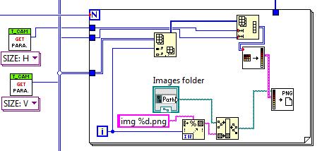
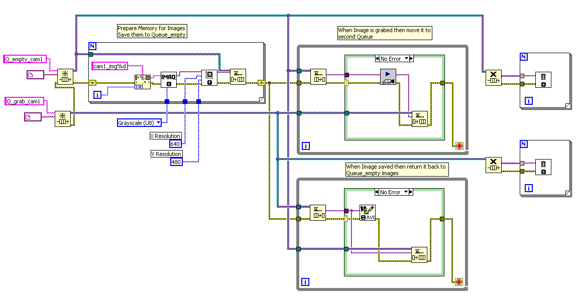
I'm trying to run multiple queues in the same loop entering IMAQdx images from several cameras, and then save to AVI. After reading the site nor a little, I discovered that the reason why I get only the last image of each bucket, repeated on all frames in the AVI file, is that the IMAQ image data type stores only the memory location for the image, not the image itself data. However, I don't see a better solution for the queues of the actual image data. What conversion could be the fastest / are in charge of the processor the lowest?

For each image you must initial Image space.
You can use something like this:
You need to add initialization camera (s) and AVI. You must add the multicamera feature. Stop recording is missing.
!!! Don't forget to throw lines and Images!
-
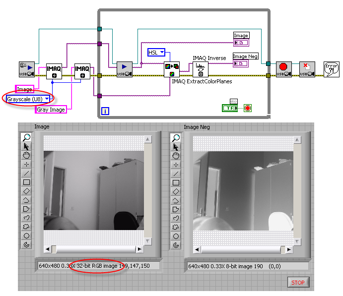
How can I use reverse imaq for USB video camera?
Hello
I'm trying "opposite" a video image live. I try to use the "Imaq Inverse" VI and it works for photos, however, I can't it works with a camera USB which is striking images.
I get an error "not an image" that occurs in the Imaq reverse VI when I image acquisition to enter USB plugged into the Img Src for the Inverse VI.
Any suggestions how to get around this problem?
I enclose two files. The "Live video" VI allows the user to acquire video directly from a USB camera. The VI 'Negative video Live' is the file I'm having a problem with.
Thanks for your help!
Hello
I guess your camera deliver RGB images (even you initialized the 8-bit image).
If so, try this way:
It will be useful,
Andrey.
-
Hi all
Please refer to the attached 2 pictures, they are similar, just the size is defferent. (pass PNG, 5478 pass. PNG).
But now I try to use IMAQ detect circles to catch the GREEN button. For the PNG pass, it works very well, but for another example, it is still does not detect this button.
I also try to change the curve settings and note that entry, but still no. Another way, I also try to use function IMAQ find circles , but the result is worse that IMAQ detect circles, so give up.
The code is detect the circles.png, copy of block diagram.
So what is the root cause? Thanks for help.
Hi colinzhang,
The extraction of curve so it uniform mode, you can get the result.
-Suggestion, if you want to use the entire image area as KING should get the size of the image, get the rectangle and convert it to the descriptor of KING. (I think this is unnecessary)
-Be careful with the extraction of the plane, u use default color which is the Red plan. In this example, it is fine. but make sure you know what aircraft you are extracting.
s ' Please find vi saved in the 2010 version.
-
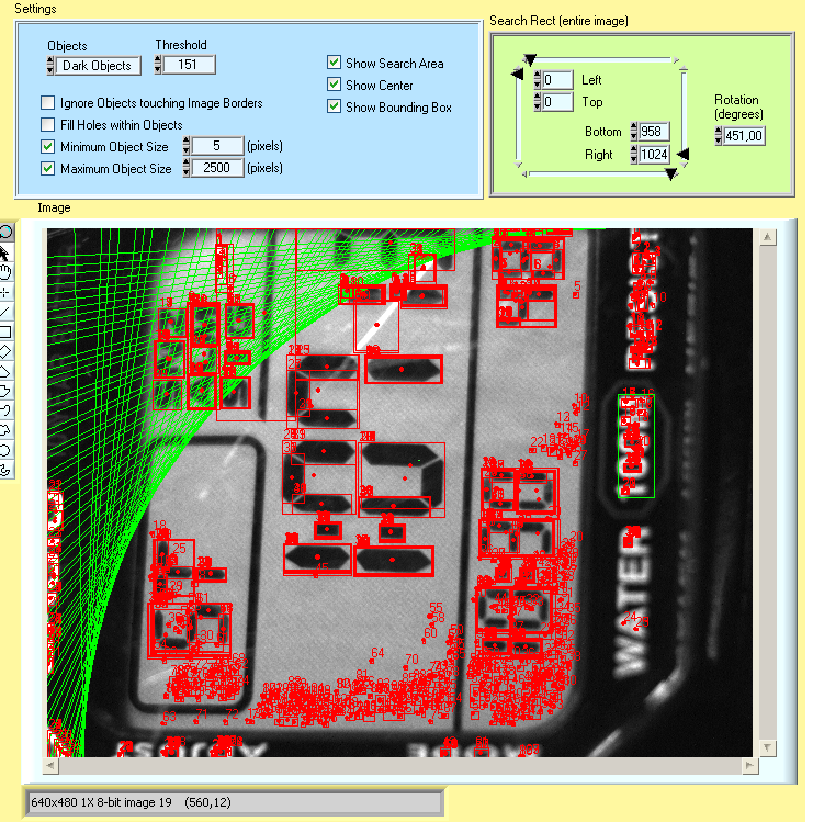
How to use count imaq objects in a while loop?
Hello, I am using objects IMAQ County and works well, but when I use a loop and I want to change the picture that I analyze to see results instantly, the search box, and the locations of the remains of the objects in the picture, even if I return to the original (for example at the threshold) values, objects of the location and the green rectangle remains there as the next image :
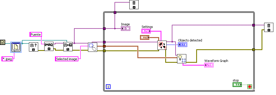
This is the pattern I use:
I used this same setup with the 3D IMAQ view and it works well, I change the values and changes in 3D view so do I.
I use unduly the IMAQ dispose?
Thank you very much for your help and comments.
Bene
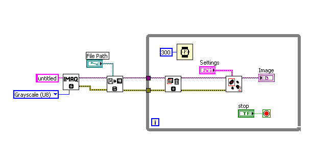
The problem is due to the way works IMAQ Vision: the thread of the image contains a reference (handle), to the image, not the image itself. Means that once an image has been changed somewhere, the mods are propagated worldwide.
The solution is simple: just add an IMAQ clear Overlay immediately upon entering the while loop (and add a small timer inside the loop).
As an example, see the vi attached.
-
I really want to get the IMAQ Image IMAQ Arry case to Image.vi files
Hello!
Although already, I installed LabVIEW8.2 and NOR-IMAQ, I don't have IMAQ Image cases and IMAQ Arry Image.vi files.
To use the infrared camera, I need them.
I really want to get the case Image IMAQ Arry Image.vi files IMAQ.
How can I get these files?
Please, let me know the methods.
Sincerely!
Thank you very much for your explanation.
Solve the problem.
Have a nice day ^ ^
Maybe you are looking for
-
How to set auto-complete command in the address bar?
I have recently updated to Firefox 3 to 8. In Firefox 3, when I chose an address outside of the AutoComplete list, very often, he would finally reach the top of the list, so I could just enter a single character and press to enter. In Firefox 8, whic
-
Full page with background does not appear.
-
What is the life expectancy of the SR memory card? They die in a few years?
-
rearrange your photos on a bookpage in photos
Hello I want to move form iPhoto photos but I couldn't find one tool that I find very usefulI: rearrange the pictures on a book page. For example, on a page with 9 photos I would change a picture lying on the right side of the page to the center of t
-
Apple Mail "search" is dysfunctional... How can I add the search right buttons?
Upgrades to El Capitan 10.11.1 and found the Apple Mail program (in "classic" mode) no longer allows me to search my emails by 'from' and 'to '. Instead, the 'research' returns hundreds of emails, I don't want to. In addition, scrolling of Inbox i