using serial port square wave generation
is it possible to generate continuous pulse uses the serial port in Labview?
Dear Ramesh,
Yes it is possible to generate continuous pulses using the serial port in LabVIEW.
The following examples may be useful for you.
Communication series - Advanced Read and Write Serial
http://zone.NI.com/DevZone/CDA/EPD/p/ID/2669
Repeated entry periodic and exit with 653 X
http://zone.NI.com/DevZone/CDA/EPD/p/ID/1840
Kind regards
Tags: NI Hardware
Similar Questions
-
Square wave generation phase offset problems using PXI6602
Hello
I'm generating 2 signals using an incremental encoder AB using a PXI6602 to simunlating.
Signals must be offset square wave, 34,133 Khz, by 90 degrees, which I'll put dividing (1/frequency) into 4 and put the result in the knot of late initial .vi DAQmx create channel (frequency impulse Co generation).
Resulting signals phase difference however does not consistantly measures 90 degrees. 1 in 5 rounds of the vi has at least a matter of resulting in a test phase angle has failed.
Can someone suggest a stable solution for this.
Thank you
David
John_P1,
After posting the previous comment, I went back to play some more with him, and he now runs and returns a positive result every time.
The change that has had the desired effect was for the type of trigger that I had selected (Advance Digital Edge). Change this to start digital dashboard whose value fall of dash, the error disappeared.
Feel free to always criticize the vi and suggest / modify to improve stability / efficiency.
All feedback is voluntarily accepted

Thank you
David.
-
Best way to generate signals of activation (square wave) with my 9401 on my 9022?
Hi, I tried seriously over the past two days to find the best way to do it. I am trying to generate a very precise square wave, controlling the duty cycle and frequency, with the OID on the 9401 in testbed cRIO 9022.
I have a VI that is theoretically able to do this, but whenever I try to go above 5 Hz or more, duty cycle and frequency becomes inaccurate (I have watch on an oscilloscope), various a lot too for my needs. I have a feeling that this is caused by my addiction on the calendar software controlled, with errors at the time (of the ms order) accumulate as they get processed and the signal is sent. I have attached a piece of code that illustrates the basic idea of what my VI have in them.
I have avoided the square wave generators integrated because I could never work to satisfaction, but I can work with them so that will solve my problems. Selection structures and cases prevent the user to exaggerate their inputs. Unwaited so the loop was just to test.
I'm running the 9022 as target in real time, but also tried to run in the FPGA and I was able to produce much more accurate signals using FPGA VI square wave, displaying a Boolean variable, but I couldn't see the best way to get double precision variables to work with everything (and I want more precision than variables FXP enabled clock 40 MHz).
I feel there is just a mistake in my approach here. I've seen other discussions where people throw around using meters to edge of the test bench to produce a square wave, and I see the example screws as Gen dig pulse - continuous Train, I'm not sure if initially these screws DAQmx for my situation (eg. How to identify my counters, because they are clearly not Dev1/ctr0 by default in these examples)
Thank you
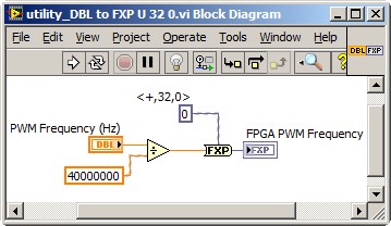
Dealing with the representation of Point fixed and all is a reality for LabVIEW FPGA<= 2011="" programmers.="" you="" might="" build="" a="" small="" sub="" vi,="" such="" as="" the="" one="" attached,="" to="" encapsulate="" the="" frequency="" calculation,="" thereby="" abstracting="" the="" conversion="" formula="" and="" fixed="" point="" data="" type.="" you="" can="" adjust="" the="" properties="" of="" the="" floating="" point="" input="" control="" to="" accept="" only="" valid="">
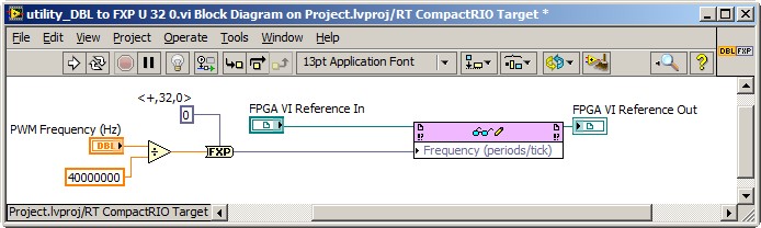
This implies the series VI void on the host of the RT, and not on the FPGA target. So, you also need nodes in the Palette of the FPGA Interface to send PWM fixed Point RT frequency to the FPGA. The complete solution of frequency may resemble the following. It is common for FPGA programmers to build a collection of thesesub screw, that make up the API for hardware.
Note that 40 MHz is hard-coded. For increased flexibility, consider making the FPGA clock rate an entry to the Subvi with a default value of 40 MHz.
-Steve
-
FPGA square wave generator diverts loop calendar
Description of the problem:
I have a simple while loop with a structure of matter inside. In one case, I have the
Generator FPGA Sinewave sending the data of output to AO0, otherwise, I have
the square wave FPGA sending output to AO0 generator. The sine and square
waves are set to run at 10 kHzI also have a shift register that changes the State of DIO0 each loop through.
In this way, I can look DIO0 on my scope and say how fast the loop runs.When I choose the sine wave generator, the output on AO0 is what I expect. That
is I have a sinusoidal signal at 10 kHz and the loop speed is approximately 1 US. Everything is good.Then I move to the square wave. I get a signal square 10 kHz, which is good. But
My loop speed was slowed down to 50 US (it follows the square wave
exactly) is: once the loop defines the FS square wave and the
the next time through the loop, it defines the square wave to-FS.My problem is that when I generate a square wave, I expect the speed of loop
to stay fast he does it for the sine wave. You can see what my loop speed
slows to 50 (a square wave of 10 kHz) and then all my calculations that must
go in parallel with the square wave will also be slowed.Please help me with my understanding of the use of the square wave FPGA sub - VI
Thank you
RichSoftware of NEITHER: LabVIEW FPGA Module version 2013 SP1
OR hardware: USB-7855R R Series deviceIf you dig into the express VI, it will loop an SSTL until there is a change in value. The sine wave has no need to do so because the value changes constantly.
If you can, I recommend doing your loop a SSTL and configure the express screw accordingly. This will work as long as the rest of your code in the loop can be run in a single clock cycle.
-
With the help of modulated signal pulse width (square wave) to control when a signal is enabled or disable
Hello all
I am using a modulated signal to labview created pulse width (square wave) to control when a signal is activated or not.
Here is my logic and a concrete example:
(1) the wave source signal is continuous
(2) use a PWM (square wave) created in labview to control when the signal is enabled or disabled
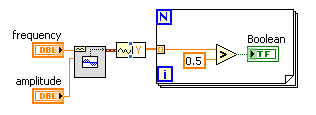
(3) if the PWM (amplitude) signal is superior to 0 play signal PWM is not greater than 0 do not play signal.I use actually this to the sequence step / pulse several distinct magnetic coils using my audio card (which has several channels of audio output), I have a signal in labview played constantly. As to compare it to the PWM (square wave) which controls whether or not the signal is played on each separate channel. That way I can control which coil is on and offshore and in what order they are activated.
I couldn't find an edge detection for a square wave created in labview, so I tried the limits, but it doesn't seem to work unless I change the phase manually and it only goes 1-1. I'm just trying to compare the PWM (edges of the square wave) already created by labview / play a signal if the pulse is greater than 0 and it shuts off the signal, if she is less than 0.
Should I do this another way
TIA
A waveform contains an array of values. You must check every value and respond accordingly:
-
What is PCI Serial Port and what will it do to my PC which has been upgraded from windows vista to windows7?
Hi Jose,
A serial port is a port of connection that uses the pins based connections to connect an external device such as a printer or a monitor to a computer. If you have a device that still uses serial port connections, you will need to add a PCI serial port to your PC.
Let us know if you need help on the issue and we will be happy to help you.
-
Using the Serial Port on the HP 50 g graphic calculator
Hello world
I have another question. I want to use the Serial Port on the HP 50 g to connect with another device. The device is called the MFJ-1214PC. What it does is to accept the text and commands through a 9-pin serial Port and converts the text in a Code Morse/RTTY sound audible. It also decodes Audible the Morse Code and RTTY radio signals and displays them as text on your computer. The program that controls the MFJ-1214PC was originally written for an IBM PC for the MS-DOS operating system. The HP 50 g graphic calculator meets the system requirements for the simplest version of the program. I was wondering if there is an MS-DOS emulator written for the HP 50 g, which would allow the HP 50 g to become the computer in this case, or if the program could be rewritten and brought to the HP 50 g. If it could be rewritten, programming language what do you think would be better suited to this type of application (if it is even possible?) or UserRPL, SystemRPL or Assembly. Don't forget that I'm a complete newbie with the HP50g and have never programmed with it yet. I'll include the manual of the MFJ-1214 PC as an attachment so that you won't have to look for him. Thank you in advance for your help!
~ Zekelegge ~.
I understand (from my brief overview) out of the box-MFJ-1214PC, this offer box decoder output series computer. The computer (50g in your case) will have the software to read message series and then convert that to an output for display.
BartDb gave you the right answer.
A serial cable with the correct speed level and reversing lever to manage as well as the 50G has a RS-232 signal to the outside world is the ideal solution.
However, make sure that the output of the decoder box series package can be understood by the 50 g. aud, bits, etc. (you have the set-top box manual, so you'll have to look that up)
the streamsmart is not an aggregator of serial port.
in other words, these connectors DIN of Qty 4 on the front do not accept series rs-232 input and send then to 50 G.
I'm not an expert, streamsmart more info on these boxes is rare to find. The probes are even more rare.
However, I know that the 4 connectors are for the analog-to-digital conversion in the probes. The streamsmart works as a "data logger" in which he sees the input probe, the A/D converted, then sends it to the 50G (or a computer via the USB port).
In addition to the solution of Bart, there was another named Tiwag forum poster who created a serial cable and displayed a schematic representation of the cable. This information can be found here:
to see an example of programming to use the serial port of 50G, you can reference the following hpcalc GPS data collection program.
http://www.HPCalc.org/details.php?id=7105
It is written in userrpl so can be crossed with the reference of users advanced for the translation of the syntax.
It seems that the main routine of concern for the comm to the gps is in the file "GPS >.
-
Tecra A10 erratic mouse then freezes when serial port used for something else
MT Tecra A10 was beautiful, but has developed a growing problem. It is running win7 ultimate. When you connect anything serial port wise it blocks indicating the Mouse / touchpad. USB mouse feezes completely, 98% frozen touchpad series same happenes when connecting via a usb emulator. Software on the laptop using series includes RS logix, perfect Omron CX1 Motion and NQ Designer, that said that they worked, can anyone guid help me pls.
See you soon
Martyn
Hello
Eventually, the software that controls the serial port or the device connected to the serial port is not fully compatible with Win 7.
I think that this should be checked first.
Maybe one of you should look for the Special Forum of the manufacturer of the software for more details -
The cRIO serial port can be used for the CAN bus communication?
I would like to order a CVC with a CAN of network device and would like to know if this can be accomplished by using a serial port integrates the cRIO (OR cRIO-9024 in my case). Is it possible, or would need a C Series module CAN?
You need a C Series module. Series and CAN use a DB9, but they do not have the same physical layer.
-
collection of data & graphical CTS (M-24) using the serial port
I work to collect data of a test (M-24) CTS station, using the serial number of the station to the serial port on my laptop.
Looking for information on the vi.
There is no driver for this instrument (I guess you are referring to this: http://www.cincinnati-test.com/sent_m24.php) on IDNET. Therefore, unless someone has already written an and happen to run across this thread, you will need to write one yourself. It is not hard to do, but you will need programming manual. There are a number of resources to help you write one: http://www.ni.com/devzone/idnet/development.htm. Since you intend to make the serial communication, you should also look over this: http://zone.ni.com/devzone/cda/tut/p/id/4370
-
To configure a serial port using Max
Hello
I inherited the code that configures the serial port using the old serial code that does not allow the user to specify the term tank and turn on the tank of the term. Any ideas on how this is done with the old serial code? I also tried to use MAX to set the term tank and allow it, I am able to communicate with my device series with Max and I saved the changes when I was. So when I run Labview code, my serial code fails because the term tank is wrong and it is also not enabled.
Everything that happens with the definition the term tank and allows ideas?
What you do to the MAX to the extent where the configuration of the serial port have no impact on the LabVIEW program. (EDIT: which means that you can change the configuration in the LabVIEW code.)
If you load the old code in a version of LabVIEW using VISAS for all the stuff of series then the screw would have been automatically replaced by shell screw that NEITHER created for the old code. Inside, they use just VISA. More than probably the old code use via digital port numbers. For example, in the library of \vi.lib\Instr\serial.llb of
, you will see these shell screw Serial Port' writing' for example, calls the 'Open Serial Driver' VI which simply returns a VISA session. It then uses the Write VISA. So you can define characters of termination by obtaining the VISA of "Serial Driver Open" resource. Of course, the best solution is to rewrite the code using VISA directly. It will be much cleaner.

-
Using the Serial Port for data acquisition Non-Serial
I searched the forums and can't find anything on this topic.
I saw that it was possible to use the parallel port for e/s digital single and I was hoping that the serial port can be configured the same. It seems all VI VISA only to use the serial port to receive ASCII characters at a given flow rate, but is it possible to simply query the status of the line series at my own speed to see if it is high or low, kind of like a single pin DAQ?
It seems that it would be possible until the serial data are read and controlled by labview, not Windows. Let me know if you have ideas of how to approach this problem, or any comment as to why it is not possible.
Thank you all!
Select the property > settings series > Modem of the line parameters. For example, the State of the CTS is an entry to the pc.
With the help of these lines is a very poor substitute for a scope or map DAQ. The only things you can return is Asserted, Unknown or Unasserted. The range of acceptable signals is important enough. Anything between + 3 and -3 is an unknown state. Your other signals is + / 3 to 15 volts. What type of signals do you really want to capture?
Edit: there is no such thing as a visa so I have no idea of what you actually use.
-
reading photoplethysmograph waveform with serial port on PC using Labview
Hello world
I'm gaining time real Photoplethysmography waveform of serial port using Labview.I have managed to acquire data from serial port by using the following features:
-Baud rate: 38400
-data bits: 8
-stopbit: 1
-No parity bit
-Time delay before reading the serial port: 10 ms (according to what was written in the manual that every 10 ms there is a frame in serial port)
After the reading string will be converted to byte array to be able to extract the bytes associated with waveform (1 & 2 bytes in a frame) even for SOP2 (6 & 7)
(what is read in serial port is in decimal and must be converted to hexadecimal based on what made the software of prodeuct for some result.that in the waveform properties, I chose the hexadecimal representation)
Then, as mentioned in the manual, I associate these two values to draw the waveform.
Although I used the filter band digital waveform of pulse but not significant pass that was seen (cutofffrequeny:10 high low cut-off frequency: 0.5).
I have attached my program and result in front of Panel and manual for the sensor. The result is still far from what is supposed to be. I was wondering if you could help me and let me know your opinion on the program and the protocol used. I have to get the result as soon as possible. Please let me know if you need more information.
Kind regards
-
Serial port in a conflict of use
I'm using LabView 11 Pro
I'm controlling an instrument that is not always connected. No problem. However, there is another program that is used by using the same port comm on the same instrument. Is there a way to weather detection that the comm port is used without question the instrument?
Trying to open the communication to the serial port using NI VISA should not affect existing communication from another application. You will get an error saying something like "device already in use.
So overall:
Just try to open the connection to the port series and look for the error. If it happens, the resource is already locked (in use). If this is not the case, your application can use it.
hope this helps,
Norbert
-
How to transfer files from PC to PC via a serial port using labview
I need to transfer files (.txt, .doc, .xls) from PC to PC via a serial port using LabVIEW. Is it possible to transfer files, if so how to transfer?
Yes, it is possible to transfer files with the serial port using LabVIEW. The files are just collections of bytes and the serial port is good enough in the expedition of the bytes from one PC to another. You must connect the ports series with a null modem cable.
First, take a look at the example of serial communication. In LabVIEW, go to the Help menu and select «Find examples...» ». From there, you can search for "serial" or navigate to hardware input and output > series. Select «Write series base» and Read.vi Try this example to gain confidence on the serial communication methods.
Then it's time to learn how to read and write files. For this, the examples might be somewhat confusing as they deal with files that are presumed to have data of a specific type in them. I would recommend just familiarize yourself with the functions in the file e/s palette. Specifically, familiarize yourself with the following functions.
- Open/create/replace file - on the side of your destination, you will need to create the copy of the file you are trying to transfer
- Close the file - when you're done reading or writing to a file, you must close it. It cleans the memory used and finalizes write operations that are still floating in the write buffer.
- Read a binary file - is the best way to play a file when you don't really like what type of file it. In your case, you just want to get these read bytes and sent so they can be written down instead of destination.
- Write to a binary file - next to the destination, is what will store the bytes in the file that you created with the number 1.
- Size of the file get (under the range of the advanced features of file) - you need to know how big the file is, so you know when you are finished.
OK, so once you are able to create files byte write and read bytes from existing files, you can move forward.
I suggest the basic method is to have the user specify a source file on the source PC, and a folder on the destination computer. Then find the size of the source file using the number 5. Divide this number of size by the number of bytes that you want to transfer to the times. The series pads are usually around 32 k (if I remember correctly) in order not to exceed that. Now start to send data by reading a number of bytes and this string output wiring to the feature of writing VISAS. On the side of destination, you will want to monitor the serial port for bytes and read when they arrive. This string of yarn to the writing of the function of binary file to add them to your destination file.
This is the basic outline of how to do it. He needs to not to overload him write and read buffers on the serial ports. Initially, you can use delays on the side sending to make sure that the side reading has enough time to digest. To make things faster, you can bring in a control of flow.
If all that sounds a little intimidating, there are there Alliance member companies (such as the automation of PrimeTest) who can write this code for you and even provides a turnkey for you solution.
Happy wiring,
Dan press
Certified LabVIEW Architect
Maybe you are looking for
-
iOS 10, screen will not auto dim.
Hello Since I updated to 10, my lock screen and home on my iPhone TO will not be automatically dim or turn off. I've updated my lock screen auto to a 30 second time out, but if I press the home button or receive a notification; the screen stays on in
-
2 major problems I want to see. 1. when I play a video from youtube, I can't raise or lower the volume of the keys of my laptop. 2nd some videos not in html5 when I push on 720 p or else it's just changed to 240 p 360 p and freezes with a black scree
-
How to save stationglobals the disk in Labview
Hi, can anyone suggest me how to save the values of stationglobal the disk when my vi is running? I update the stationglobal property set API TS call in my vi. But when I left the TestStand and open again the old values of stationglobal are still the
-
Hi allWe are working on our future architectures.A seller from an oracle reseller told us that we could use the oracle database RAC extended to build.He said we could use two ODA, then activate a node by device and use those two boxes to create a RAC
-
Files included in subscriptions
The company I work for is interested in Adobe Stock, they want to just check what file types are included in subscriptions before you buy.Photos, illustrations, graphics and videos are included in the subscription?Everyone can check?Thank you