VISA connection terminals
Hi all
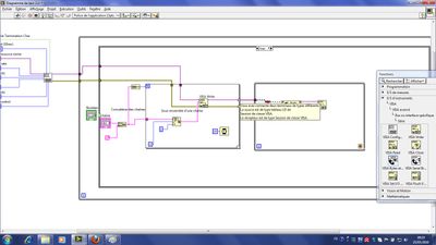
I wanted to take over the existing application on the forum "Fact Serial Port operation," but I could not connect the two terminals of the VISA. the error message is 'you have connected two terminals of different types.
can someone tell me how adapter a table 1 d of class session to a receiver of type session of class visa.
Thanks, JB
on your recommendation, the connection is made and thanks again.
Tags: NI Hardware
Similar Questions
-
How can I connect terminals to a vi in order to to use in the other vi?
I created a vi that returns some numbers and I want to use these numbers in an another vi by adding the first vi in the block diagram. I need to create a sort of my first vi output terminals and I don't know how. Can someone help me please?
On the front panel of your vi, right-click on the icon in the upper right corner (under the x). The third option is show connector (left-click on it). You will now see the side of the connector. Using the tool of wiring, connect the small white boxes to your orders and such indicators as desired. If this model is not good for you, you can use some other custom models (same menu) or create your own. It is likely that it works perfectly.
Good enough?
-
Ini file importing visa connection problems
Hello
In the Test Import Connections.vi joint, I try to import a resource (COM3) of a configuration file name. Import the keys in an initialized global functional. The functional global is read and the output is sent to a production cluster. However, after running the code, I always end up with an empty string for the name of the resource in the cluster of production. When I run the vi within the main application, I get an error 3, (or the possible reasons: LabVIEW: internal error.) Area of poorly accessed memory. (= OR-488: GPIB controller does not correctly addressed.) (I don't have a GPIB controller in my system.)
Any ideas why it does not work?
Thanks for your help.
Peter
With each entry, you are erase all previous data in the shift registers. You must run 1 writing or make a check for each setting see if it is updated.
-
Visa connection Media Center AT and T Uverse Motorola cable Box
I'm trying to get my Uverse box to understand the codes it receives from my new Vista Mediacenter PC (HP Pavilion M9600T). I am able to do Mediacenter during installation to accept/learn the codes of my Uverse remote but unfortunately when I then try to change channels the uverse box interprets false codes missing numbers or using false numbers. Anyone knows how to go beyond this issue?
Hi David,
Thanks for your help. I followed in fact already this sense arrived at a point that WMC learned codes Uverse remote but then again sent incorrect codes to the box. I then went in and actually disabled the Hauppauge Remote Control Board in the HP unit via the control panel and connected an external transmitter via the USB port. It worked. I'm now able to change the channels correctly.
Interesting enough, I had my PC Pavillion replaced because of this problem, as I expect it is a hardware failure, but the new unit has exactly the same problem.
His works now for me, but I wonder if HP knows they have a problem in their high-end line Media Center PC?
-
I am creating a labview program that controls two different pieces of equipment. One is a linear step Thorlabs which is an ActiveX device connected via a USB connection, and the other is a brushless motor controller connected via an RS-232 (with VISA) connection. I have separate programs that work separately with each unit. However, when I try to write a single vi which does both, the program fails. Sometimes the connection to linear step fails, and I receive a message saying that the USB connection has been lost. Sometimes, the program hangs and I have to restart Labview. The two different connections could interfere with each other? If it is possible, is it possible to check to confirm or refute this possibility? And if so, is it possible to keep them from disturbing each other. Both devices are from different companies, so I'm not likely to get any help from one of them.
Thanks for any help that anyone can provide.
BF
It sounds good, but I suggest also using error in / error and take the active x is also connected with the error in/out and no parallel, as it is now.
It takes a little more time but of course no conflicts should occur.
sequence frames have the same function as the sequencing of wiring!
-
Error signal processing VISA via MatLab script
Hello
I'm doing a simple acquisition of a VISA connected multimeter voltage feed voltage reading (it is a picture, but I only feed the frist for this example element, until I managed to make it work) and use a MatLab script with a build-in function to trace this tension. I get an error and I don't know why... Can anyone help?
P.S. I know I can do this simply and easily everything in LabView, but as a result of specific class, I have to do interfacing between LabView and MatLab.
Thank you all in advance!
Records,
G.
Hey everyone, managed to fix it myself. Apparently need to sit and read the documentation on the MATLAB script more carefully. The function that I used was not recognized, I guess... or the MatLab server is not able to run it. However, I simply removed the function and the script automatically recognizes the values for the variables of interest, powered 4 from the LabView code.
-
I can't access my account of direct mail since my father connected to sound on my pc
My dad came for a visit, connected to my PC with his Live mail account and since then I can not connect to mine. I lost all of my contacts, the works! How to bring back my stuff?
Windows Live questions belong in the Forum http://windowslivehelp.com/
-
Notice of VM, SunRay2 terminals - Sun Server necessary?
Just a quick question here.
We are planning our new display of VM system, we plan to use SunRay 2 terminals to connect to computers of the users.
My question is;
Do we need to buy SunServer software so that the SunRays2 can connect to VM view? IE SunServer acts as a broker/bridge to connect terminals to the sight of the VM?
Thanks in advance...
Try to install the latest Java
don't overwrite the existing java but
-
From a ReadWaveform on an external trigger?
I have a DigitalMultiChannelReader that I need to start reading a waveform when a change of external line. For example, I want to read Port3 lines 3 and 4, when PFI5 is high for a number of samples.
readWaveformTask = new NationalInstruments.DAQmx.Task ();
readWaveformTask.DIChannels.CreateChannel ("PXI1Slot6, Port3/Line3, Port3/PXI1Slot6/4", "", ChannelLineGrouping.OneChannelForEachLine);
() readWaveformTask.Timing.ConfigureSampleClock
"",
samplesPerSecond,
SampleClockActiveEdge.Rising,
SampleQuantityMode.FiniteSamples,
samplesToCollect);
readWaveformTask.Stream.Timeout = 1000;
readWaveformTask.Triggers.StartTrigger.ConfigureDigitalEdgeTrigger ("PXI1Slot6/PFI5", DigitalEdgeStartTriggerEdge.Rising);DigitalMultiChannelReader reader = new DigitalMultiChannelReader (readWaveformTask.Stream);
TODO: How to make the player doesn't start not the task here?
drive. ReadWaveform (samplesToCollect);The above code will start the task and start playback of the waveform as soon as 'drive. ReadWaveform (samplesToCollect)' is called.
How can I trigger a waveform acquisition using an external trigger?
CurtisHx,
In fact, even if the roads of the device shows a direct link between your PFI line and the trigger in MAX line, it only means that there is a possible link between these lines. You will still need to manually connect these terminals, which can be done easily with the method DAQmx connect terminals. If you need a detailed method explanation, you can find it here.
-
Cannot detect the limits of reverse front/market
I have problems with the switches front and rear for my stepper motor system. When I created a NI Softmotion axis in Labview, no matter how to set limit switches, either appear as assets or both inactive, regardless of the position of the platform. I use for my end of race, photointerrupters. When I don't have the equipment under voltage, the photointerrupters works as expected and give a signal of 0 V when the platform is not the limit and V 5 beeps when the platform is at the limit. But when I try to use the Labview interactive panel (or in a VI elsewhere too) the limits are not detected and behave differently as well. I got a voltmeter connected to see how the tension behaved and pressure readings are odd. In a case when I tested the 'active' signal of each switch, was one of the limit switches to 6.7 V and the other was at 3.7 V, even if they had the same exact wiring and configuration. I'm completely stumped on how to connect these in the system so that they work or how to configure Labview to properly recognize these limits (meaning sourcing vs shipwreck and active State power). I searched the forums and manuals, but I can't seem to find a solution. Here are more details on the system:
The engine is now a platform back and stepper motor is powered by a Kollmorgen P70530 stepper drive. To communicate between the command of stepper motors and the computer, I use a cRIO 9076 with a NI 9512 in the chassis. To connect the end of race in the system, I used the NI 9512 connection block 37 pins. Switch in the photo that I use is a strong GP1A05 CIPO Photointerrupter with connector. For this photointerrupter, there 3 pinout: a Vcc input (voltage source), a GND input and output Vout. The SCR is supposed to be connected to a source of 5V and GND to the mass (obviously) with resistance to pull-up between Vcc and Vout (I use a k 10 Ohm resistor as who has what has worked for me in the past with this specific photointerrupter). Vout is supposed to give a signal 5V, then the limit would be active and 0V when it is not active. How I had connected the photointerrupter to the connection block 37 pin was as follows: to the limit before, I had the VCC to pin 9 (+ 5V OUT), GND was on pin 3 (COM) and Vout was on pin 1 (before the deadline). For the inverse limit, I had the VCC to pin 9 (+ 5V OUT) GND was pine 24 (COM) and Vout was on pin 20 (inverse limit). I also tried to connect terminals GND the switch of the photo to the GND (shield) pin on the plate at terminals without success either. In regards to Labview, I am running Labview 2011 SP1 on my computer.
If you have any ideas, I would greatly appreciate it if you would share that I am really confused with something that seems on the surface to be quite banal.
Thank you
Steve
Steve:
I am puzzled too-
Manaual I looked:
http://www.NI.com/PDF/manuals/372153d.PDF
Your PIN seems correct.
I assume you have a power supply connect to Vsup and COM.
Research on page 3-10 for sourcing of the shows without pullup resistance, have you tried remove the 10Kohm?
But watching page A-3 for levels of limits, it shows<5V for="" low="" and="" 11-30v="" for="">
I'm confused-pg 3-10 looks like the 9512 provides its own pullup still pg A-3 show the necessary voltages for entries.
I hope someone can clarify this.
-AK2DM
-
Hello
I have a small question on an example of clock by RTSI source.
In my configuration, two PCI cards (PCI-6602 (dev2) and PCI-6110 (dev1)) are connected by a RTSI cable.
I would like to build a clock on 6110 source sample and use it on 6602 counting external impulses of entry.
In the MAX test Panel, I checked that a meter was reading of external signals.
However, the vi attached do not work, and the whole County, and then give an error of 200284.
Could you tell me what is the problem?
I guess that something is not right on the clock signal routing. I have to use DAXmx connect terminals vi instead of external signal?
How can I check that both devices are connected through a RTSI cable?
I recorded the cable and connected devices on MAX with no problems. Is this enough?
Thank you for your comments and kind suggesion.
Several things briefly:
- Must match the orientation of the RTSI cable. Connectors are generally indexed to ensure this, but if you use a cable in water House, just keep it flat between the boards.
- The code you posted attempts to use the time base internal 20 MHz as a sample clock. That will not work for several reasons, and the fact that you try suggests you may have a poor understanding of the functioning of the meter. You do * not * need to "sample" at a pace high in order to catch the digital transitions. The meter circuit manages everything in the material. What you "sample" in a task of counter is a County registry value. Digital TTL edges which are worth little matter how many times you "sample" it increases.
- I suspect you want to * account * cycles of the clock of the signal of your 6110, be it a train of pulses counter or a sample clock based on the tasks.
- I am writing an example that does without buffer sampling clocked by the software, to approximately 10 Hz. Dev2 uses to generate a pulse of 1000 Hz and uses Dev1 train to interrogate the County registry value in a loop. It is simple from the code you posted to help unravel the special problems of routing RTSI config problems. Start using something simple like this to see if DAQmx succeeds routing signals through RTSI.
-Kevin P
-
Synch series AO DAQmx with DIO
There are not many examples DAQmx for AO series.
Can someone give me an example of how do I synchronize using outputs analog DAQmx on the digital master with exit/entry table on a Board of the slave?
I have an AO Series PCI-6723 (Dev1) and a DIO PCIe-6535 b the (Dev4) connected via a RTSI bus. I've defined the RTSI, using MAX cable and added the two devices.
Have had no success and cannot find a suitable example.
I'm on a Windows 7 computer that runs Labview 2012.
Thank you
Gretchen
I found a solution! It is complex, but it seems to work.
I used DAQmx export signals VI & DAQmx connect terminals VI.
See attached VI.
Gretchen
-
USB6259 static with digital trigger
Hello
I have a VI that controls a control of linear motor with digital lines. At one point in the program setting one of these pipes triggers a task of analog input and a task of Pulse counter. This is done by putting a wire between the digital line and for example. PFI0 use this as a the input trigger. This works well.
My general question: is it a solution, where I can use an internal signal of the 6259 avoiding the connection of the wire?
Matthias
Hi mq17,
I have found no clear information, saying that it is possible (or impossible). What you should try is to create an internal route between the digital line and PFI0 using the DAQmx connect Terminal VI. I can't guarantee this will work, but it's worth trying:
DAQmx connect terminals (VI)
http://zone.NI.com/reference/en-XX/help/370469AA-01/lvdaqmx/mxconnectterminals/
Don't forget to unplug the terminals at the end of your program
Best regards
-
I'm starting a project to automate certain measures using Labview 2009. My Lecroy SDA 18000 is recognized by MAX VISA TCP/IP and seems to send the chains survey welcome back. I downloaded the LCWAVE driver that is supported by NEITHER. When I try to run the vi initialization or other I get an error 85 as shown below. I don't know what to do as all Labview drivers, I used in the past has always worked. Any help would be appreciated.
Error 85 has occurred to lcwave Error.vi of playback control
Possible reasons:
Scan of string (arg 1) in LeCroy Wave Series.lvlib:Read command Error.vi-> Query.vi Series.lvlib:Error wave LeCroy-LeCroy Series.lvlib:Initialize.vi-> Untitled 1 wave >
The format of the CMR? the answer is not as expected. Make sure that the command header is not being reprogrammed to the value configured in the default configuration VI Instrument, where it is set to OFF with the CHDR OFF command. (Default as Setup.VI Instrument is called from Initialize.vi.)
«"" "String of full appeal:»»"»
Wave of LeCroy Series.lvlib:Read command Error.vi
LeCroy Series.lvlib:Error Query.vi wave
LeCroy Wave Series.lvlib:Initialize.vi
Untitled 1Hi, Alan LeCroy Technical Support here...
The selection "control of the" East on the oscilloscope. in the scope, go to utilities > utility configuration... and then the Remote tab. There are several selections: 2 choices for connections LAN, LXI (VXI11) and TCPIP (ACIP), GPIB and outside. (The ACIP choice has existed for a decade, LXI is very recent and a likely cause of the problem, given that the pilot is not completely calibrated for LXI. (Even if it is compatible).
To connect to the scope you describe, you must use the type of connection (LXI). When you use TCP/IP (ACIP), MAX has no way of knowing that the scope is there. (MAX is not designed to connect with all types of instruments controlled by LAN)
Here is a link to an application note that I wrote on how to use the LXI interface; It could be very useful.
http://www.LeCroy.com/TM/library/AppNotes/LXI/LXI_Interfacing_AppNote.PDF
The point here is that you must use a VISA connection string that corresponds to the type of connection selected on the scope.
Best regards, Alan
-
With the help of LabVIEW 2009, I want to direct the output of ctr0 to several PFI. I looked at a lot of positions, but I'm still a little confused on how to route to multiple output.
It seems that there are three possibilities - DAQmx connect terminals DAQmx export Signal and DAQmx Channel property node.
Is it possible to get a pulse ctr0 to multiple output? If so, which of these options is the best? (I guess I'd several calls to the terminals or export Signal) Is there a limit to the number of exits can I drive with a signal ctr0?
Thank you.
Hi rls.
The best way to achieve this is to use the DAQmx VI of Signal to export. You can route the signal to several roads by selecting to go... rather than select a single line PFI, then CTRL + click on the roads to do. I was able to do this on a card PCI 6251 M Series multifunction with no problems.
Best,
Maybe you are looking for
-
Sierra, stuck in the 'Downloaded' status
The Sierra dmg has failed with an error "invalid checksum". I would like to re - download the file to see if it has been altered during the download - but the app store has the gray Sierra drop-down selection in a status of "downloaded". How can I re
-
model MB565ZP Version 2.0.1 120 GB what generation?
iPod classic 120 GB Model: MB565ZP Version 2.0.1 S. n.: 8K914BPG2C7 - to which generation does this belong?
-
How can I put a pdf flyer into the body of a message?
Several times a month I send a group message. Before that I have attached a pdf file that is a flyer with info. I want to send the email with the flyer just there in the body of the message (not as an attachment).Have had no luck so far and would app
-
Annoying Message "not connected" when TV goes to the Source of ATV4
I use my Apple TV 4 as one of the three input sources for my new 65 ' 4 K Samsung TV. TV uses its system Anynet + (HDMI-CEC) to control the switching and control of the three entrances (the other two are cable box and a Blu Ray player). This works p
-
Combat Flight Simulator won't save is no longer a new campaign
I tried to launch a new campaign in 3 bag after beating the HUN. I created a new American character and flew the 1st mission. Then I dutifully saved the campaign according to the instructions of the obvious. After leaving the game, I tried to continu