Meter output routing
With the help of LabVIEW 2009, I want to direct the output of ctr0 to several PFI. I looked at a lot of positions, but I'm still a little confused on how to route to multiple output.
It seems that there are three possibilities - DAQmx connect terminals DAQmx export Signal and DAQmx Channel property node.
Is it possible to get a pulse ctr0 to multiple output? If so, which of these options is the best? (I guess I'd several calls to the terminals or export Signal) Is there a limit to the number of exits can I drive with a signal ctr0?
Thank you.
Hi rls.
The best way to achieve this is to use the DAQmx VI of Signal to export. You can route the signal to several roads by selecting to go... rather than select a single line PFI, then CTRL + click on the roads to do. I was able to do this on a card PCI 6251 M Series multifunction with no problems.
Best,
Tags: NI Software
Similar Questions
-
Meter output that uses as AO start
Hello everyone,
I am currently using a PCI-6120 with a BNC-2120. In VI I have attached to this post, I have an analog output channel that generates a predefined signal stored in the memory of the Commission. Regeneration is activated so that the signal is emitted continuously.
The generation can be stopped and (re-) started at any time using a switch on the front panel.
Outside this AO channel, there is a counter. I would use this counter as the trigger to start for the AO, so that, when the switch on the front panel is set on WE, the AO task waits for the next rising edge of meter output to start the build.
Here's my problem.
When I run the VI, the first beginning of the AO is in fact triggered by the meter. The two generated signals are perfectly synchronized (AO and Ctr). BUT! After putting the switch to OFF and then back on, the signals are not synchronized more. AO task starts generating right samples after the start of the task, without waiting for the next rising edge of the output of the counter.
Could someone help me understand what is happening, please?
Why it works just after the execution of the VI, but not after using the switch on the front panel?
Thank you very much.
P.S.: when the switch is off, the AO job is not completely stopped. The OD begins to generate a constant value of 0 Volt. It's normal. I want to check the value generated by the Board at any time to avoid damage to the unit that I send the signal. So I force the generation 0 Volt, rather than simply stop the task.
LucG,
According to the S-series user's Guide, the time will be two impulses of your time base clock sample. So, it is expected.
The delay of the 2 tick must be for an internal sample clock. There should be no delay if you use an external sample clock.
You can check whether this delay appears when the sample clock is also used as the trigger for the start. I didn't realize this test.
If it doesn't, I think that your solution will be to buy another Board because I have already spent time yesterday to try something else like using the counter of seconds for example, but it really seems that there is no work around except buy a Board with a more recent technology.
Kind regards
-
Multichannel synchrobized meter output daqmx c#
Hello
I am facing the following problem:
I'm a piezocontroller operating to move a microscopic sample. The piezo allows me to scan XY of the sample areas. At each position analysis (to each "pixel"), I count photons for the image of the sample. Photon counting is a simple measure of pulsewidth and isn't important here.
What is important is that I have two types of piezo controllers in different configurations. A controller is digital and I can send the coordinates of the area to be scanned. The controller then allows me to define 4 output triggers to synchronize movements piezo with other operations such as opening and closing of shutters, photon counting after each pass of the step to a new position etc...
However, the second controller is an analog that only allows me to adjust the tension to move the scene. If I want to recreate the functionality of the digital controller I need to create four trigger lines myself.
So, my solution should look like this:
(a) I have a "clock" that ticks with a cycletime of 200 microseconds. At each tick of the clock tension in my piezo for X and Y motion are incremented. Master clock ticks are also triggers for the photon counting tasks at each position.
(b) the firing in four, used for various purposes, should behave as described in the two attached screenshots (pictures say more than 1 million words!). If for example it takes 1000 the master clock ticks to complete one scan line, then the line 1 trigger should for example be placed high the first 500 ticks, trigger line 2 should be high ticks the next 500 while line 3 trigger must be high all the time. This behavior must be repeated each line scan etc etc...
Is it possible to have this kind of coordination between the output of 4 meters to say, an edge of 6601?
Any help would be greatly appreciated!
-
to detect the meter output via the parallel port
I need to detect the meter count trigger, to perform an operation every time. I think passing the input signal pins (pins of status or control). The meter uses is omron H7EC.
I lowered the voltage of 24 V to 5 v with resistors.
But I can't get the entry via the parallel port.
All the stems of my status are still high.
What should I do, please help.
In the parallel reading write loop.VI, the splash screen is attached.
I suspect the entries on the parallel port pins have a resistance low pullup to 5V, so they tend to float high (logic 1).
Try to add a 4 700 Ohm resistor between pins of entry and mass of the parallel port, see if it then reads down pulldown (logic 0). If so, then keep the resistance in place and connect the signal of 5V that you want to monitor at the entrance.
-AK2DM
-
PXI-6133 Pulse frequency output and input with DAQmx
I am trying to set a pulse meter output frequency task and read this signal with a frequency counter input task input pulses. I use a 2 PXI-6133, each connected to a BNC-2090 case has. I want to output a square of a certain frequency with the task frequency meter pulse output and then read the frequency of this signal using a task of cost input frequency. I don't know how to property set up these tasks, or how to define which device to use for each heap. I don't know what terminals on the BNC-2090 is the counter of entry/sortient channels correspond to them because that is not displayed in the documentation of the PXI-6133 or documentation of BNC-2090.
Please see the attached VI for my attempt to put this in place. Currently, I get two errors:
(1) error-200452 took place at the property Node DAQmx channel meter Test - referred to as property is not supported by the device or is not applicable to the task.
2. the error-89136 at DAQmx Start Task - specified route cannot be met because the hardware does not support.
If I remove two channels of property DAQmx where I try to put the terminals for the counters, while the program is running, but then I know not what terminals on the BNC-2090 meters are connected to! This causes the DAQmx read for the cost in the tasks of frequency to timeout because it does not detect a signal.
I would really appreciate the help to properly configure these tasks and determine what terminals on the BNC-2090 case has the task of counter will work on.
I see a few problems in the code originally:
- For your CI task, you type is defined as a counter entry > frequency. But on the node property of DAQmx channel for this task, you modify the CI. Property of PulseWidth.Term. It should be CI. Freq.Term. set the entry regardless of the PFI line you do not want the input signal on. Tip: you don't have to type the name of the device in at all. Enter "PFI0", it's the same as "DevN/PFI0" since the unit has already been specified in the DAQmx Virtual Channel Create function. The name of the device, leaving aside will make your code more flexible where you decide later to change the name of the device.
- Maps of the S series, such as the 6133, do not have the same flexibility to change the output terminals of tasks of meter you might find with M or X series device. Page 83 of the S series manual watch what signals can be extracted to PFI lines - Ctr0Out is not one of these. Instead, Ctr0 out is, by default, pin 2. Cabling to a BNC-2090 6133 is certainly difficult to understand out (probably because the 2090 was designed to work with the materials of the E and M series), but if you compare the pinout of a PXI-6255 0 with the 6133 pinout connector, you will notice that they are essentially a match 1-1. Pin 2 is PFI12 on the 6255, so I assume the same for the 6133. All this to say, Ctr0Out always appears on the pin 2/PFI12 for the 6133 and you therefore cannot change the output terminal that your code is trying to do, having for result error-89136. Remove this node from the property altogether and the error should disappear.
-
Is it possible to use the internal clock for meter tasks in the buffer?
Hello
Hardware: USB term mass 6251
Software: LabView 2011 SP1
I need to measure the angular lever position and speed of a carpet. For that I use two quadrature encoders. To accurately calculate the speed I use buffered from the measures of position using one of the available onboard counters. I understand that for this technique, I provide a sample for the meter clock. I wonder if it is possible to use the internal time base. Note that both of my counters are used so I can't generate a signal to clock with them.
I found two conflicting pages related to my problem:
1) http://digital.ni.com/public.nsf/allkb/EA7FFFEAFC3E1D85862572F700699530
2) http://digital.ni.com/public.nsf/allkb/775290A3121D1FFC862577140074D3B3
The first says that I can use the internal clock of 100 kHz, and the other says that I have an external clock.
Comments/solutions?
Javad
Hi Javad,
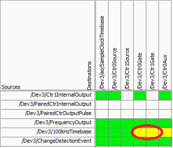
On your specific device, there is not a direct route from the time base of 100 kHz for the meter (according to the routing table of MAX):
Yellow cell indicates that a route is possible but there is not direct (the "gate" terminal is used as sample clock for counters of the M series). Mouse on the cell reveals yellow that make this route really requires the use of a counter (so it is not suitable for your application).
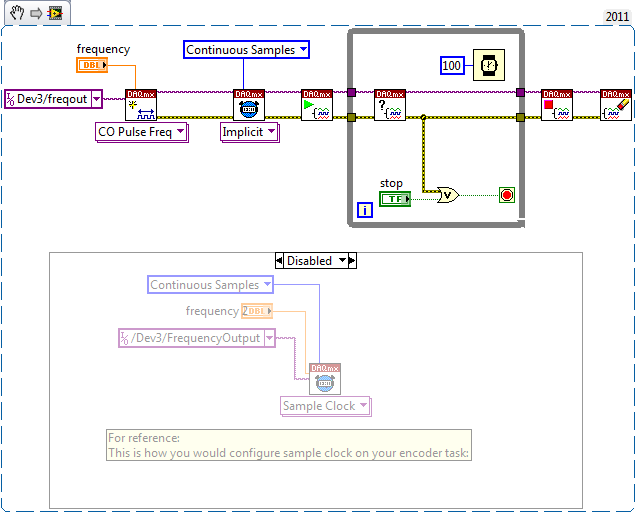
On the line above "100kHzTimebase" you will notice it is called 'FrequencyOutput', which does not have a direct route to the door. This would be the way to go if you want to route 100 kHz (or some other frequency) as your sample counter clock - you can set it up the same way to a standard meter output task:
The output frequency doesn't have that many features like a meter output, but it is able to generate a continuous stable frequency. There are only 32 different frequencies that can be generated using Freq Out on the 6251:
{10 MHz, 100 kHz} / {01:16}
Do not forget that the resolution of your measure of frequency by using this method will be equal to how many times you update the measure (hopefully, that makes sense). In other words, if at the end of all the 1 second, you take the total number of charges since the last second, you would have a 1 per second equal resolution change in the number. If you take the difference twice per second, you would end up with half the resolution. You will be sampling the account register fairly quickly, but you will need only to do the calculation of the frequency after that all N samples in order to obtain a significant number.
Another method that will certainly give a higher resolution in less time at typical speeds of coders is to set up a measurement of the frequency (the counter will count the internal 80 MHz base time period your external signal and the pilot calculates the frequency based on the result). This method uses only a single entry - so you can just feed the 'A' your encoder quadrature signal (the method will not work if you are interested in absolute position or direction). Without using signals A and B together, you will be susceptible to noise (which is common to have a quadrature encoder) that you want to delete (perhaps by setting up a digital filter). Finally, you want to set a reasonable timeout on your reader calls (which will be blocked until a period of your external signal occurs), and the error-200284 handle simply report "0Hz" to make sure that your program is still sensitive even without an external signal present.
Best regards
-
synchronize two exits of meter 6071E map
Well, that's usually how to synchronize two problem of counters.
I use the 6071E with DAQmx .NET 4.0. I set a task and attach to two channels with implicit synchronization and zero initial delay of meter output. When executing the program
I catch the first edge with a single trigger to scope. There is always a delay between the first edge of ctr0 and the first edge of 16.3 microsecs ctr1. Is it possible, not to mention that affecting the initial delay of ctr0 16.3 microsecs to make meter always start together? What is the source of the delay(software/hardware) and must always remain constant.
any help is welcome
The source of the delay is that while he is in the same tasks that the counters are always started sequentially by software. I'm surprised that the delay you see is constant.
If you want the counters to start together, you must configure a start trigger. As soon as you begin the tasks of meter in the software, issue the trigger to start to generate your pulse output. Relaxation of beginning must be a signal of material - for example, you can configure a digital outputs in software timing and the lead back to one of the PFI lines.
If you want to avoid any additional wiring, you could split the counters in two separate tasks. Trigger a counter with the internal performance of the other (start the task that will be triggered everything first). In doing so, instead of using an external trigger, I expect a delay between the order of 100 ns counters as the initial delay is at least 2 timebase tick.
Best regards
-
DAQCard-6036E - meter channels synchronization
Hello
We have three devices we want to synchronize:
-' pressure' gives us an analog input
-"valve" needs a square via channel 0 counter wave pulse
-' cam trigger' needs a series of pulses of square via channel 1 meter wave
It works as long as it is the regulator OR the shutter of the camera is attached to the pressure. But when we are together, we get error 50103: resource is reserved. Does this mean I can't use two meter channels at the same time? At least that's what I guessed read other messages in this forum... Or sync not working correctly?
Someone has any idea how to solve this problem, or what alternatives are to use the channel to counter?Thank you for your help.
AndreaHello Andrea,
Thanks for the photos.
I did some research on the synchronization of the two outputs of the meter. Unfortunately the DAQCard-6036E does not support to synchronize the 2 exits of meter
Therefore, you got the error.
The reason is technology OR TIO, who only is not supported for cards E-Series.
Click on the following link:
Material Start Trigger counter for counter sync
http://digital.NI.com/public.nsf/allkb/9C657EE63C9D07A686256F6D0062AC66?OpenDocument
There would be an option if you have a cards M or X-Series with an ARM-Trigger
Synchronize two tasks of meter output using a task HAVE dummy
https://decibel.NI.com/content/docs/doc-11755
Kind regards
Rupert Donauer
-
How can I specify a delay generates a pulse meter?
Hi all
I have a question on the use of the meter to generate the pulse train. I did not how to program but I try the test panel in MAX and I see that it generates pulse train to certain rates and with a pulse duration. I think if it is possible to generate only a single pulse with given the duration of the impulse to sometimes after I start the job? I have a code to generate an analogue waveform, waveform of 35ms. I wonder if it is possible to synchronize the output of the analog waveform and counter such to 12.5ms after that the output waveform has started, I send this unique pulse from the meter port on. I have no idea how to do that, I think to use a delay but it is difficult to accurately control the time exactly 12.5ms.
Well, assuming DAQmx_Val_Low for the resting State, fires the meter will wait the initial delay and then generate a pulse at the time you request. Little time is not actually used in this example simple impulse.
From what you described, you must add a trigger to start your task of meter output (DAQmxCfgDigEdgeStartTrig) to you can set the meter to trigger off the beginning of analog output trigger. Set the initial delay on the counter for 12.5 ms. Start the task of counter in front of the task of the analog output. You should get your pulse 12.5 ms after you have started the task of the AO.
Best regards
-
Specify the end point for the digital using an output circular buffer
When you use DAQmx and a NOR-DAQ for issuance of a digital signal using a circular buffer (buffer Renault). The program works and works, but when the 'DAQmx Stop Task.vi' function is called to end the task, he stops at the output buffering as soon as it is called and does not wait until the buffer pointer reaches the final value in the buffer. I would like that the program to wait until the buffer pointer is on the last value in the buffer, does anyone know how to specify this setting?
If you need to stop on exactly the last sample output you will need a way to trigger the stop in the material. The options available to you will depend on what hardware DAQ, you use, but here are some possibilities on the top of my head:
1. set up a digital output redeclenchables task finished (not all hardware supports). Set up a counter of output to issue a periodic trigger with the necessary synchronization signal such that the end result is a "continuous" digital output without interruption. When you stop your loop, stop the task of counter - digital output ends his generation but the trigger signal will be removed and so it will not continue after that.
2. If you have an unused extra digital output line, add it to your task. This line should exit 0 all except the last sample. Physically, this additional digital line in a wire line PFI and use it to trigger a meter output. Have the output counter generate a single pulse of some long-term (long enough to ensure that the software can respond prematurely). Use the output from the task of counter as a trigger of break for the task of digital output. Do not start the task of the meter until you leave your loop. Do not stop the task of digital output until you have detected in the software that the meter has been triggered.
If you need to stop on approximately the last sample output, you could query the TotalSamplesPerChannelGenerated property after leaving your loop and only stop the task once it reaches a multiple of the size of your circular buffer. This is no guarantee that it stops on the last sample (if you use a device on a bus with a latency higher as USB or Ethernet the non-determinisme would be worse).
Best regards
-
PCI-6115 counter 0, 1 output current capability?
Can charges of 50 ohm PCI-6115 player with the counter 0 or 1 meter outputs? The specification data sheet had no information on that.
Hi src42,
The data sheet indicates the maximum amount of current that can come from the digital lines to 13 my @ 4.35V. This unfortunately not sufficient to drive a 50 ohm load.
Best regards
-
How do I output a digital signal to an analog signal
Hi all, I use a PCI 6221 with LabVIEW 2010 (no add-on) with the CB-68LPR connection block and I want to use an input signal analog of voltage of between 0 V and 5 V of an LDR to change the brightness of an LED, so I can maintain a stable lighting for a webcam capture feature level image and treatment system.
I can get the analog input voltage of the LDR (set up as a voltage divider circuit) using the DAQ assistant, via the channel of Ain 0 on the use of pins 68 (AI.0), 67 (AI GND) and 14 (+ 5 V) and write it in a graphic and digital display but I don't know how to write the value to a PIN that can be used for PWM I think assistance from pine 40 PFI 13 P2.5 and a digital (GND pin 13).
I looked at the example of code that was written to produce a PWM signal, but these programs don't signal to a device/circuit, they are just "nothing stuff" that the PWM signal to a graph.
Can someone help me or direct me to tutorials/code examples which are of real-world applications?
Hello
PWM can be done in DAQmx using a task of the meter output.
I think that example 'PWM-Counter Output.vi' goes quite a long way to do want you want I think. It is located in the LabVIEW examples of shipping.
I also found here:
http://zone.NI.com/DevZone/CDA/EPD/p/ID/1710
This could be useful a read thus:
http://zone.NI.com/DevZone/CDA/tut/p/ID/2991
Let me know if it's of any help.
-
Help explain the flow meter VI
After a lot of tinkering, I seem to have developed an effective VI for use with a type/pelton turbine flowmeter. The flow meter outputs a stream of pulses which
can count on the counter of my 6501 line. Unfortunately this eureka moment happened somewhat by chance, and I'm hoping someone
could be kind enough to explain step by step or in terms very simple for beginners (me) works of VI, thank you.
Kind regards
GER
GER,
Welcome to the Forums and LabVIEW.
If you don't the have already made, please work through the tutorials online to get started with LabVIEW. The answers to some of the questions you may have are probably there.
A brief description of your VI:
1. the overall structure is a loop For. It works for the number of iterations that is connected to the Terminal in your case 5 N.
2. the calendar of the loop is determined by the longest time required for any part of the code inside the loop execution. On the first iteration, the DAQ Assistant configures the counter and starts measurement. On all subsequent iterations, he reads everything simply an indictment. On these iterations, the 25 les 25 ms ms expect will dominate. This VI runs approximately 40 iterations per second (for 5 iterations).
This means that the program will take place on 5 * 25 ms = 0.125 sec and then stops. If you run for more 1/8 of a second to help run it continuously button, STOP. Which is intended for certain types of troubleshooting only.
3. the table of waveform and the flow rate meter only shows the last value of the five iterations. (This suggests also that you use run continuously)
4. the registers at offset in this VI nothing do. The upper shift register calculates the cumulative number of the flow meter, but the result is never used. The underpass registry has nothing connected to the Terminal inside the loop on the left. It could be replaced by a terminal.
Suggestions:
1. in order to avoid using run continuously, replace the loop with a while for loop. Add a stop button on the front panel and connect it to the stop it real terminal in the loop. Move the graphic terminals of waveform and flow inside the loop.
2 check your pulse to the algorithm of flow rate. The time for the count interval must be considered. For example if the meter registers 25 pulse in 25 Member States, which represents 1 000 pulses per second. This isn't which will show your VI.
3. see examples of code that uses counters.
Lynn
-
Question on the meter battery upward
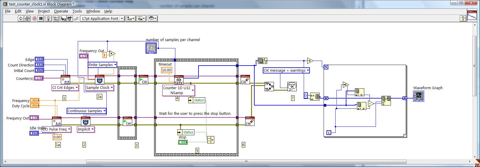
I want to detect the meter output of fixed sampling at a specified sampling rate. The following code works, but I found that the output array is a pile up of the previous charges. I so get the actuals for each sample by subtracting the sequential values. Is there a way to get the value directly, without piling up? Because stacking upwards can easily saturate the meter buffer, and it has no advantage. Any input is highly welcomed. Thank you!
Hi xipeng,.
The "Frequency" of your task of CO Pulse Freq entry is not wired. By default, it is a low frequency, and so the clock does not produce enough samples fast enough.
Best regards
-
I hope someone can point me in the right direction and also to clarify some concepts!
Background: I am currently using the box USB-6009 and labview on a laptop to output 2 analog waves. It acts as a waveform(0.5-2Hz) of speed (periodic) for an engine step by step (with a driver) to execute a loop of traffic, and the other waveform acts as a signal short 5V to trigger some imaging equipment. The ability to move or to delay the start time of the wave of 'trigger' compared to the waveform of speed in steps of hail (ms) became a requirement for my experiments. Given the time where the USB-6009 case, software based accuracy was not good enough because I need, and the way I wrote the VI limits my delay/travel at the speed of wave deltaT(30-40ms). I started to look at the USB - M series (portability is an obligation) since some have calendar based on the material, and I could send the signal to a buffer rather than iteratively having read every value of the wave in. It also seems that a digital short "pulse" works better than an analog wave form creating any. Where I ran into some confusion is to determine the requirements of a deterministic way sync the two. I am looking for new hardware. I started by looking at the box USB-6211. However, I ran across a few posts talking about the digital I/o correlated being required to perform vaguely similar configurations, which would require something more like the USB-6221. Since I have probably to the digital output to be on a time scale different analog output, is i/o digital correlated required? If not, would the 6211 work?
Just to be clear, I need the periodic waveform and relaxation to be constantly in phase (anywhere, 10 minutes to several hours). Then be able to move the pulse +/-1ms (minimum) and repeat. I can justify the most expensive device if necessary, but I don't want to get something I don't need.
I have attached a figure (not not to scale) of what I am after, in the likely event that my explanation was not too clear.
Thank you
Gabe
Hi Gabe,
The 6211 did not buffer IO digital as some of our other devices. However, there are two complete meters on the 6211 which can be used to perform a generation of pulses (pulse or continuous pulse train - you can output a pulse train using two counters finished). You can take a look at the section Applications of meter output x 621 manual for more information.
What it sounds like, the 6211 will do what you need for the following reasons:
1. the AO of the 6211 lines are buffered and can be clocked up to 250 kHz per channel (in contrast to the 6009 using AO NI by SW).
2 the 6211 counters can be used to generate two pulse based on a basis of time of 80 MHz (12.5 ns pulse width and resolution time). The 6009 does not output meter.
(a) if the two pulses must be on the same line, you must configure a task of generation of pulses finished' (this example uses two meters behind the scenes).
(b) if both impulses are on separate lines, then you can use a task to counter separated for each line with a different initial delay.
The 6211 does not supported clocked generation of digital signals (e.g. 100010101110100) but if you just need to generate impulses so that's precisely what the counters can be used to. I think that's where all the confusion, but seems like the generation of digital signals should not be necessary for your application. Trigger the counter outputs out of the trigger to start AO and adjusting the parameter 'Initial period' should give you what you are looking for. Don't forget to start the tasks of meter in the software before the tasks of the AO (if they are armed and ready to go before the start AO is sent).
I hope this helps, don't forget to post if you have any questions!
Best regards
Maybe you are looking for
-
Replacing the battery next USA
I bought t my laptop from the United States after 3 months, I come home (Bahrain)I'm in Bahrain now and I checked the web site of Toshiba I found advice to replace the batterySo I call the dealer to Bahrain and get the information that the dealer won
-
Icon blackBerry Smartphones BBM missing after the update. need help ASAP please
Hi I'm using a bb bold 9780 and my bbm is 5.0.1.45 and when I tried to update, it hangs whenever he finishes the installation. And when I got tired of a battery pull, my bbm icon is missing. No idea how to solve this problem? Could really use some he
-
How can I access my CC Lightroom catalogs when internet is unavailable?
How can I access my Caralogues of ambient light CC when no Internet is available?
-
Since a windows 10 update on 09/12/15 my lightroom app will does not start I tried signing and return in, restart, reload the application, it will not start either from the desktop or the app cloud have other people encountered this problem?
-
Problems to download Adobe Photoshop Lightroom 6!
I am unable to download Adobe Photoshop Lightroom 6 for Windows (Lightroom_6_LS11.exe) but got the message' Sorry, too many download attempts: 5. you were allowed to upload only 5 times. If you have any questions, please contact Digital River Custome