Waveform... Problem
Well, I take (multichannel ADC) entry of A Microcontroller.i.e uC 6ADC uC has done its job and sends serial...
My problem is when I use a waveform of writing file...
the PDM contains more than 2 values at once
That's why when I o/p is the evil waveform... its much igger (sense of time)
How to build a waveform with instantaneous values of Amplitude
What is the file .tar you home?
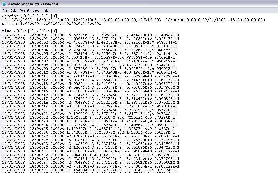
Looking at your screenshot, I see the timestamps in your table. You rely on Windows calendar to get the timestamps? Do you know that Windows has only a resolution on its clock of approximately 16 milliseconds? That's why you see several pieces of data with the same time, then he jumps 16 milliseconds.
Tags: NI Software
Similar Questions
-
How to add a record button on the front panel to save waveform data
Hi, I'm new kind of LabVIEW and I worked on a code for an agilent oscilloscope communicate via GPIB and so far it works well on the collection of these two analog channels one by one, "Not UNLIMITED" but it does the trick (vpp, Vrms, frequency, etc.). I've added the feature to add data to a .csv file waveform (problem: opens a dialog box until the user gathers all the data.) Solution: I want the user to save the. File CSV whenever he wants to use later on the front panel). I've added another feature to get a snapshot of the curve waveform (problem: opens a dialog box.) Solution: I want the user to save the JPEG file, whenever he wants to take a snapshot ("take snapshot" button on the front panel)). I work with the agilent hp54645d driver. I have attached my code, if someone can tell me please how do I do this (maybe cabling and structures are solutions do not know). Thank you in advance.
I would recommend adding a case structure just around the two record VI and a button to check the condition of the structure of each case. If you want a button to control both save functions you can put the two record functions in the same structure of business controlled by a single button. You are right in saying that the loop will cause your code runs until the stop button is pressed or until the stop condition is met. If you are wanting the while loop to stop once the recorded information you can use the button that you use to control structures case to also stop the while loop. I hope this information helps.
-
Problem more then 16 output waveforms
Hello, I made a program to 30 waveforms output, but when I try more then 16 output signals, the program show the internal software error error occurred in the MIO software. Please contact the support of National Instruments. I use two NI 9264.
Please help me
Thanks for the supportWhat cDAQ chassis do you use? The cDAQ-9172 supports only 16 hardware channels timed, but the other cDAQ chassis do not have a limit unless you perform an on-board regeneration which you are not.
What DAQmx version you have installed?
You should never get this internal software error is a problem with DAQmx. I don't have two 9264 s in my office at the very, but I can try again later to see whence the error.
-
problem with the history of EEG waveform data
Hello world:
I use SIT to create a user interface in Labview to communicate with a simulink model. After I configure the SIT connection manager and run the vi, the output was displayed in waveform graph.
Now, I want to get all the data in the history of the map of waveform. I tried to use the graphic story property node to access the whole of the historydat. But nothing copied in the part of Y in the front of the cluster of waveform...
Can someone give me a helping hand on what is the problem? or has anyone encounter the same problem when you use SIT. I am really confussed...
I've attached the vi, but to run the vi, you must have a simulink model corressponding and SIT, so I'm really sorry that you can not run it
And thanks a lot a lot a lot for that.
/ Shangning
I just realized this data is a 2D waveform table, which contains the waveform 2000 * 1, and each waveform data contains only 1 value of Y.
-
Hello
I have a difficulty with the vi LabVIEW "waveform of the generation" I wired all the entries on the vi: dt, t0 and there, I have a correct timestamp, but when he connects, my wave repeat myself it is 01/01/1904?
I tried my timestamp on the example vi: create the sample waveform, and here it works? I don't understand? What I am doing wrong?
In the room attached my vi
Best regards
Thijs Boeree
I don't see your problem. If I enter a time stamp valid in your header BDF, then run your code, I get the same timestamp in the waveform. More specifically, where is your problem?
-
Having a problem with discontinuity in the waveform
Hi Experts,
I am trying to build a multipurpose vi which is capable of generating analogue signals and read at the same time, using USB-6251 and Signal Conditioning connector block model SC-2345. I intend to add a signal from the sensor to the waveform in the future, but this is not the case now. However, when I run the program, it turns out that for a small discontinuity in the waveforms which I have really no idea how to solve this problem. And it's completely unacceptable, because it affects the shape of the wave and its frequency. I have attached the file. Any suggestions would be greatly appreciated.
Sorry if my English is causing problems. Thanks in advance.
Sharon Thanesvorakul
Student
There are some questions that could be the cause. First of all, you reset the function generator every time and you're not ready for continuous production.
-
I have problems using the command 'writing of the waveform to the file. Perhaps the problem lies elsewhere. The problem is that even if the path is correct on my front panel indicator, a file is never created. The path to the file is created by using the location of the folder and by creating the file from the timestamp of the time of execution of the program. I would be grateful if someone could explain a solution.
Curtis
Your loop never ends? This wave function to write to a file is outside the loop, then it won't work until once the loop is completed.
-
graphical waveform shortcut menu problems
Hello
We discovered a problem about shortcut menus on maps of waveform with our current installation of LV2009f2.
In the development environment ("IDE"), we have created a larger application. In the display section, we have several graphics (waveform), where the user can select the signal traced by the contextual menu (aka the context menu). When running the application in the IDE so good, the menus are displayed with all of the elements, we have defined.
So we have finished the debugging (so we thought) and created an executable. Then, we tested the executable on the same computer (the computer with IDE installed full). Everything if fine, context menus are shown as expected.
So, we got to the next step in the creation of an installation package (which resulted in a size of 0.99 GB btw...). LabVIEW makes no complaints and we have installed this app (using the Installer) on a clean computer. No problems so far, our application has started, everything was fine. But then we tried to change the display: NO POPUPS! Instead, we had error 1165 (problems with Insert on the Menu, "Can't find the menu"). What happens here? Anyone with a clue? Where is my menu (reference)?
OK, we had a second computer. Install this package of 0.99 GB too. From the app: just fine, except the missing context menus!
More information:
All computers are Windows XP, Service Pack, even. Context menus don't require no RTM file, so no missing additional files in the installation package. Menu references created by LabVIEW (IDE or RuntimeEngine [RTE]) on right mouse click on the control, so that there should be no problem with the benchmark missing or false. The values supplied to generate the menu are the same for the IDE and RTE, so no difference. The graphics are incorporated into a secondary, but still only had events for them, so we no problem. New: the reference for the menu is provided by LabVIEW (event "Activating the context menu", MenuRef), so it should be valid...
Sorry, no example. It is difficult to reproduce, when it only happens to RTÉ and only on computers, where no IDE is installed...
Tomorrow we will fill to the top of the VI for creating menu with a lot of debug message subVIs to check everything and everything is going on in there...
Hi Norbert and others.:
I found a solution for my problem (after a long session to create exe, deployment to a different computer, debugging and start all over again...).
In deployments executable the shortcut menu for the chart is missing (and is missing only here!). So I first test a menu empty on each activation of the menu and create a new menu if necessary. To do this, you will need to turn off (disable) "default DURATION of the context menus" during the VI containing the graphic.
A note more:
All other paid (menus VI other) are loaded correctly, all loaded screws work dynamically. It's only the RTM shortcut missing... (And the RTM file is set to 'always include' in the application Builder!)
-
Waveform display and the data flow problem
Hello
I have a mission and I am facing difficulties in a number of things.
I wonder to monitor the level of CO and NH3 and the level of measured in ppm following the equations:
for CO: 50 * (1-exp(-t/7000)) and NH3 is 35 * (1-exp(t/12000))
The first problem, I do face is the trace of the on a waveform table.
How can I draw on the graph of the level of CO and NH3 simultaneously / bundle tried but it don't did me not a graph.
The second problem is that when the condition of the structure of the capital letter is true the loop stops running; How can I solve this problem?
Thank you
-
Timestamp problem DAQmx waveform
I have a program that reads analog signals multiple DAQmx using a PFI trigger from a DIO card to start the acquisition. It uses a registry to offset and Boolean logic to stop the DAQmx read the loop when the trigger is low. I traced the result to a curve of waveform. I have a 1000 S/s scanning speed. I traced the data to a graph of waveform and eye on the individual data points and it is perfect. Exactly 1 S/s. The problem: when I increase my 5000 S/s scan rate... I see exactly 1 S/s, but the displayed duration of my test data is 5 x more time. That tells me that my graph of the waveform is plotted in fact each data point individual 1ms apart. So basically, there a 1ms all dt in the waveform, and it does not change. How can I get the real dt of the analysis of data here instead of this arbitrary constant? When I look at a text of my waveform data file, I see the timestamp below where I'm expecting something ending like that... 0,0010, 0,0017, 0.0025, etc.. Any help would be appreciated. I'll post the VI if necessary, but other than the trigger power, is a fairly straightforward HERE DAQms read. Thank you in advance.
The time of LV start date is January 1, 1904 midnight GMT. Since your shows up to 6 hours before that, he must be GMT - 6. My horodateurs base are 19:00 31/12/1903, which is GMT - 5. Eastern time zone.
Are you any error coming out after your Subvi waveforms?
You empty an array of waveform data to add. The default waveform has a T0 zero and a detachment of the 1. In the Sub - VI of waveform append inside your Subvi if dt' it does not raise an error, (in fact a caveat being the 1802 error code is positive.). But she proceeds to add data and use the dt and T0 the first waveform which is initially as the default data in the initial iteration. I think that if you start with an array of wavefrom that has the number of channels of the need, an empty array of Y, but a correct dt. Then the dt should be correct. That, or you can put in your Subvi a case structure where the first call, or if the incoming waveform is empty, it is not add and uses only the 2nd waveform.
You have also a little a Rube Goldberg enters your Subvi. It could be simplified as shown in the picture as an attachment.
-
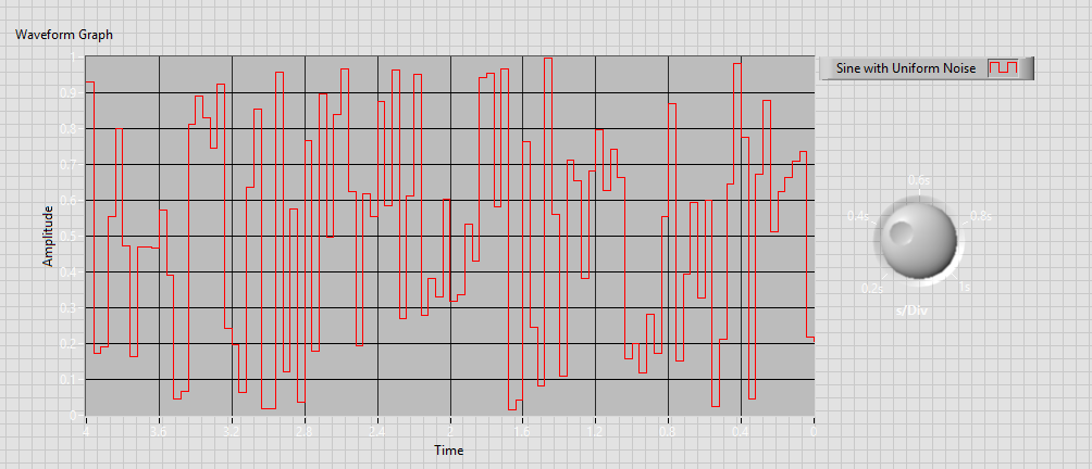
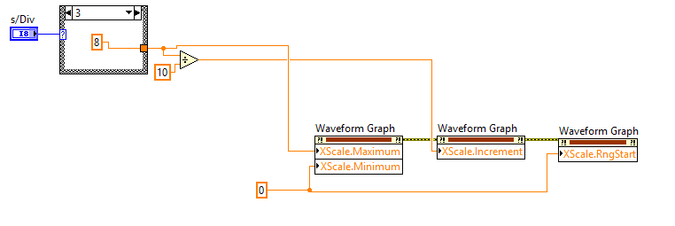
I'm working on a graph of waveform for a project, I want to use a node to control the time of the chart base. It works, but switching during the chart will display more divisions that I designed for a very short period of time, which is annoying. I have attached the vi and I'm appreciated if someone could help me on this problem.
Just found the solution, it seems that I sequence the function of the node of the property or the graph will be confused. Your suggestions has informed this solution. Thank you!
-
Waveform of Agilent DSO5054A read problem
I'm reading signals oscilloscope with LabVIEW, but when I read the waveform, instead of the real tension, numbers ranging from 0 to 2000 ~ appears in LabVIEW VI. When I change the position of the wave on the oscilloscope, these figures are also changed. Please check the picture below. Are there settings I'm missing? Tensions on the scope are about 5 volts. Help, please.
Hello
You are using the wrong driver.
Try
http://sine.NI.com/apps/UTF8/niid_web_display.model_page?p_model_id=10028
Curt
-
problem while conspiring waveform of the signal in real-time
Dear Sir
I use LabVIEW8.2 and USB1208FS for data acquisition. I have configured hardware with LabVIEW and data in real time using the Universal Library VI AInScBg.vi. When I draw my signal on the waveform (amplitude vs. frequency) then on axis x frequency ranges from 0 ~ 0.49 hz. I have change the sampling rate of 1000 Hz to 4000 Hz, but on the x-axis without frequency change occurs and it is set at 0.49 hz. Can you please guide me how can I get the frequency of my own interest on the x-axis.
I enclose you daughter of LabVIEW for reference.
Kind regards
Muhammad Irfan
Student
UTP Malaysia
0060149087570
Simply change the text label of the x-axis of frequency does not automatically the correct calculation. You do not pass in the sample information in the service spectrum, so you get no frequency information. You can see the strain on the entry point. The function expects a data type of waveform as input. Without it, the dt will default to 1. Then, use the function create a waveform and add information from dt to it as well as your table of Y.
-
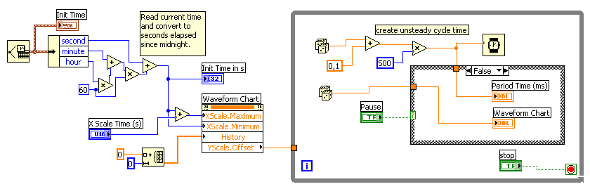
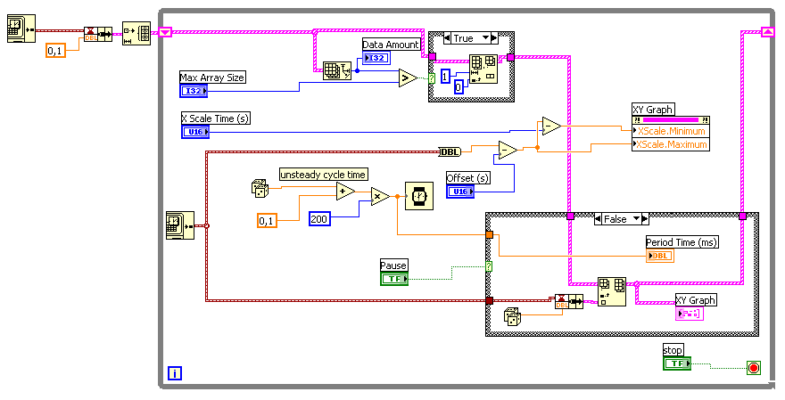
Problem with table of waveform: time scale do not see the time correctly
Hello
I have some problems with a graphic.
I want to display data, and the duration between two unique data can vary. It's something between 50ms and 500 ms.
The problems I have:
1. the time is not correctly displayed in the graph (allways 02:00:10 instead of the current time)
2. the data points in the table have a distance of 1 s (x-scale). This is not correct.I've tried several things, but I thinkt that I am on the wrong track.
Could you please help me?Johannes
LabVIEW 7.1 (!)
I'm sorry. The property on the left node was not necessary...

-
Problems with playback of waveform in MATLAB files
Deal all,
I acquired signals on 2 A/D channel (using the DAQ M USB-6215 map) and save them in the file of waveform using WriteWaveformsFile.vi. But the transformation (FFT, elippse fitting, fitting sinewave) I want to use these data in MATLAB. I tried some options like waveform of conwert bin file, but I can't get this data into MATLAB correctly. I also convert waveform data (or data from a waveform) using WriteToSpreadsheetFile.vi, but still I can correctly get data in MATLAB. I'm not sure what I'm doing wrong. Thanks for your help on any tip. I use matlab R2009a andLabview 8.5.
Tomaz.
Hello
Saving the data in a file, please use Scripture for measurement files (express VI) and configure for *.lvm, without column header and time. So since this file *.lvm is a normal text file, try to read it in matlab.
Thank you and best regards,
srikrishaNF
Maybe you are looking for
-
Why the update did slow my MacBook pro down so
Why the update did slow my MacBook pro down so much? What could be in the last update of El Capitan to slow my Mid 2010 GHz Intel Core 2 Duo Macbook Pro 2.66 down so much? He has never run it slow before! Everything takes more time in all areas. Co
-
HP Probook 650 G1: How to disable the keys way to Probook 650 G1 running Windows 7, 64-bit
I just bought a HP Probook G1, intel i7 650 - 4600 m, system BIOS 01.34-08/28/2015, keyboard review KBC 16.3 C version. ESC and F1 through F12 function keys seem to be in the Mode of action key (for example flight gives HP, F6 system information allo
-
DIAdem 11 Setup error: object required: navigator, display.currdataProvider
On the Diadem 11.0 installation, I get a popup error message when I open the program first (and subsequent) time and the browser, view tab is corrupt: Object required: ' navigator, display.currdataProvider. Also when the program is first opened after
-
How do I get spell check for outlook express?
I have windows xp pro. I can't spell checker for Outlook Express. It shows f7 in the Tools section, but it does not work. What should I do?
-
How to eliminate the border for PopupScreen?
Hi all! I am trying to create the ToolTip for the components. I guess I should use pop-up screen for this. But I do not border there. I want just a simple rectangular tooltip. Without any decoration around it. I tried to replace protected Sub applyTh