When the waveform is acquired
Hello
I use the example code to control my scope (Tektronix 2024 (B).
I need the VI to inform when the waveform is acquired - at the moment.
How can I do?
Thank you
Ariel.
Here's the basic idea
Tags: NI Hardware
Similar Questions
-
To generate a sinusoidal waveform of given the frequency of acquiring data 6251
How can I generate a sine wave of given the frequency of acquiring data 6251? I tried to use the generation of waveform of the signal processing Toolbox, but it seems that it is written that the first or the last sample, not all. I have faced this condition when I tried to write through 1 d double multichannel analog waveform.
In the examples, look at Gen Con voltage Wfm - Int CLK.
If you continue to have problems, according to the code you have written.
-
Mulitcam: Waveforms disappear when the audio "Fill left" applied
I often waveforms disappear when you are working on Multicam sequences. Often frustrated and unwilling to understand, I'll just copy and paste the audio right in the sequence of work. Often this myself when I need to just adjust the audio set.
I just reduced the issue of the audio application "Fill Left with Right". I'm not sure of the correct terminology here so bear with me.
When I first create the Multicam sequence and place it in the timeline, the waveforms are projection. However the audio is displayed is not the audio OK (neck tie). In the stratified sequence where I can adjust each file in the multicam sequence, I muted the incorrect audio layers leaving the direct reverse and use the proper effect of "Fill Left with Right" or "fill the right with the left."
Switch back over the sequence mulicam and waveforms are gone. 'Cancel' and they are back!
It is true that I could make this change on the Multicam sequence but I learned that it is not best practice.
Advice or wisdom?
I'm blocking projects often and this problem does not occur every time. I tried to restart first with no luck. I use the latest version.
Do you really need to see the waveform in the nested sequence multicam?
If so, made Audio.
-
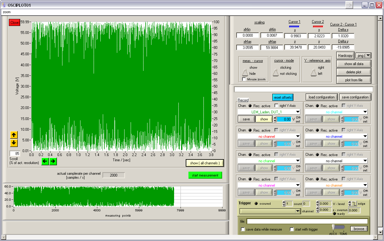
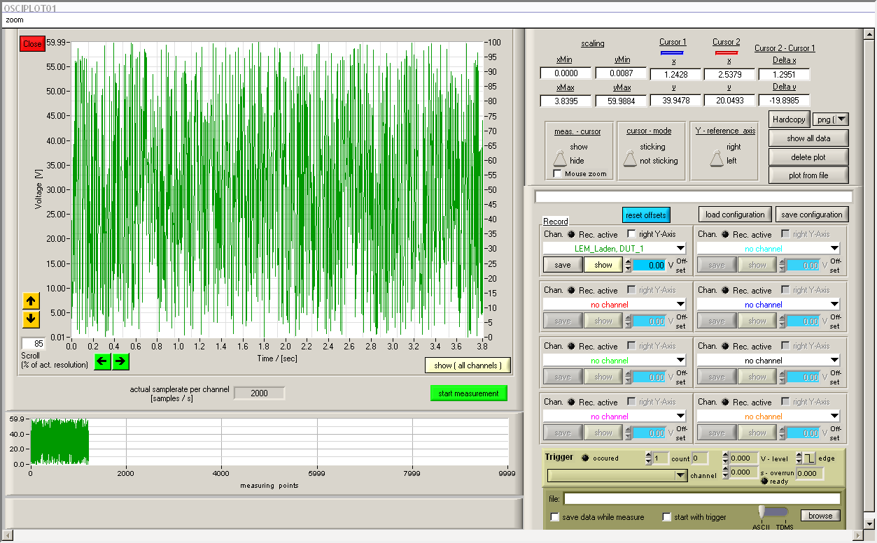
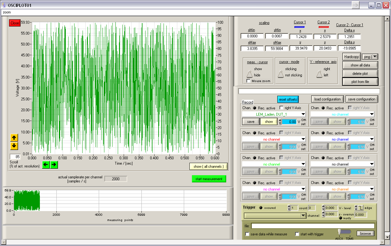
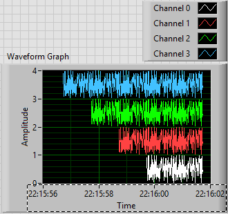
How display the waveform acquired DAQ card separately in wavefrom graphic
I NI 9239 DAQ card and it has four channels. I need to create a user interface graphic labview in which I need to display all the forms of four wave separately. If I select all four channels of the daq assistant and connect the waveform table all four waves are coming to overlap... I need separately for the treatment... what should I do?
Thank you and best regards...
Try this
-
Hello NOR community,
I'm new to LabView and was hoping someone might be able to help with a question I have. Currently, I use a data acquisition unit to sample external sine and I would like to change this signal by adding another signal that I could control using the front panel. Whenever I try just connect entry with something like the waveform sinusoidal vi and put a subtraction sign between them it doesn't work (I get an empty waveform graph). To work around this problem, I've resorted to a signal (via an analog output) and followed by reading the signal to data acquisition, and then finally I add the two together. It works this way, but he wastes two channels and I imagine that there is a better way. I enclose my VI, and I have marked the location of interest "where signals get subtracted ', which is currently displayed using two entries.
Thank you
Leo
You must ensure that your sampling frequency and number of samples is the same. It seems that your sample (with default values) rate is the same (1 kHz), but your number of samples is different (100 to 1000 the acquisition wave vs simulation).
-
Hello
I have a problem when I want to save a screenshot of the Panel with the GetPanelDisplayBitmap & SaveBitmapToPNGFile functions. The screenshot of the Panel is done when the Panel is hidden or inactive. Thus drawing events don't have facts.
Please take a look at the attached screenshots:
(1) manual measurement and life-saving operation, the saved data is ok
(2) measure hidden and functioning economy, the saved data is not correct, the axis were not my updates
(3) bring the Panel forward, axis had been updated
Is it possible to force an update of the axis without back panel to the front or set it as active panel?
Best regards
Vitali
1)
2)
3)
I think that it is a bug of the CVI.
This is how it works:
-SetCtrlAttribute (Panel, control, ATTR_ZPLANE_POSITION, 0); without this step the axes will be not updated!
-for each channel {PlotWaveform ;} (.)
- ...
-
Updated reading (waverunner 6100) scope of the waveforms?
I use an oscilloscope (LeCroy) waverunner 6100 and able to get the waveforms of the via drivers downloaded from NI.com. But I would get a waveform only when a new acquisition happens (not not to read the same waveform all the time). How can I do? There is a "read only waveform.vi" available on the site, but it does not work with AUTO trigger mode (I think). I am currently reading in waveforms while loop with "Fetch waveform.vi", but I'm not sure that it reads as "refreshed" display... Here I read some registers (whatever) status or there is already an existing solution?
Hello Alex Harley,
Alan LeCroy Tech Support here. The waveform read various screw run the command 'Arms', so it is not for use in Normal or automatic trigger mode. We recommend that you use this command, because it uses the unique relaxation mode, which is the mode to use when you want your program to control when the scope triggers and so make sure that you're reading data retrospectives that corresponds to a specific triggering event.
If you prefer to run in automatic mode or Normal mode, you must use the VI 'Wait to acquire full' which is located in
the range of data/Low Level function. The looks for the registry "INR" testify to a new acquisition.Best regards
Alan
-
Convert the waveform (DBL) to a cluster of 2 elements
Hello
Can someone help me to convert the data type of waveform (DBL) to a cluster of 2 elements (X, Y). I found a few examples online, but I get an error when I wire everything together. I use VI of Tektronix to acquire a signal of channel 2 of my noculars, which I am able to do, but now I want to convert this data to a cluster so that I can use it for an existing application to acquisition. I have attached my VI version 8.2.
1Thanks
The is easy since it is part of the waveform data type. The X, you will need to calculate based on the dt by using a loop FOR.

-
battery patches option while using the VI express acquire
Hello
I have my daq, NI USB-6009 acquire a current analog signal of input ai0 and acquire an analog input voltage using ai2. These signals is acquired at the same time in a task using the daq assistant express vi. The data are connected to a waveform chart that is seen by the user on the front panel. When I start the program, the program works well, however the waveform and the voltage wave are superimposed on a single diagram.
I want to show the signal from analog voltage and current analog signal separately on two separate parcels. However, when I right click on the graph of the waveform on the front panel and choose the menu option, the "stack slots", nothing happens. The plot does not crack.
Help, please
Thank you
Mary
Hi Mary,
Have you tried to expand the legend of field in the upper right of the map of waveform? The following knowledge base article contains measures for the display of multiple locations as individual screens.
http://digital.NI.com/public.nsf/allkb/21E8163F259DA2058625703B007511AA?OpenDocument
-
I gain the waveform. refresh rate of VI
Hello
I would like to move the update rate (which governs how many samples is acquired per second) for the vi - tied Acquire Waveform (waveform) .vi.
This vi is built in vi can be obtained from the range of the analog input under measures of e/s.
The preset of update rate is 1000 samples per second, I want 10,000 per second.
If I manually type, it does not remain and back to 1000.
I'm using LABVIEW 8.6 on the Windows XP-based computer
Thank you very much and greetings
Poli
What do you mean there's not? It remains to what you set it to. Do you mean that there are no when it closes? If this is the case, of course not. You will need to right-click on it and select operations on the data > made by default to the current value and then save it. However, it is not something you should anyway. Do not make changes to a VI expedition. You place this in your main VI anyway and pass parameters with controls or constants.
And why you use obsolete traditional DAQ driver?
-
L50 - B satellite will not start when the battery is completely discharged
Hello
My Toshiba L50 - B won't start when the battery is fully drained but connected to the power outlet.
I try to work most of the time on the battery to keep the battery in good shape, but when I forgot to turn off the battery drains and the system will not start when I plug in the adapter.The battery charge indicator is orange light as it should. Only when the battery is fully charged to 100%, it will run at startup and function normally after that. I tried to turn on the laptop several times during the charge cycle, but only when the charge indicator changes from yellow to white it starts. Tested for 2 bodies.
My old Toshiba always immediately turned on when I plugged the adapter even when the battery has been completely drained. Am I missing a setting somewhere?
Thanks for responding... I hope well :-)
Toshiba L50 - B
Windows 8.1
Any standard/original setting since I only acquired this laptop a month ago.The laptop should light up if the power adapter is plugged in and power the laptop corectly any if the battery is empty or during charge.
Please check the version of the BIOS that is available on your mobile phone and compare with the BIOS available on the page of the Toshiba UE driver
Maybe you need to update the BIOS, but to be honest, the history seems really odd to me and I m afraid that there could be some power supply electronic problemSo in the worst case, the laptop must be checked by authorized service provider.
-
missing samples in the waveform graph
Hello world
When processing a file .wav into pieces, I noticed that there are missing samples on the waveform graph where two pieces must be met for the display. What could be the cause of this? Any help appreciated. Thank you!
Milan
Your method of reading in pieces in a for loop is create a table 1 d of waveforms with the tunnels of automatic indexation. It is as well as what you have the data appear in different plots. I don't know if that's what you want.
But if this is the case, the problem is that you get to the last point of the first plot, and the first point of the next parcel is a different value. Because they are two different plots that you do not get the line to join them, as you do between points that are part of the same plot.
-
Having a problem with discontinuity in the waveform
Hi Experts,
I am trying to build a multipurpose vi which is capable of generating analogue signals and read at the same time, using USB-6251 and Signal Conditioning connector block model SC-2345. I intend to add a signal from the sensor to the waveform in the future, but this is not the case now. However, when I run the program, it turns out that for a small discontinuity in the waveforms which I have really no idea how to solve this problem. And it's completely unacceptable, because it affects the shape of the wave and its frequency. I have attached the file. Any suggestions would be greatly appreciated.
Sorry if my English is causing problems. Thanks in advance.
Sharon Thanesvorakul
Student
There are some questions that could be the cause. First of all, you reset the function generator every time and you're not ready for continuous production.
-
I have a chart single 2D out a conditional of a loop indexing output such that over the rows of the table are not the same size. -Basically, they have different starting and ending points and sizes. -Not so concerned by the endpoints, because as soon as I get correctly starting points, everything shows fall in place.
The challenge is that when I try to have the variable t0 (start time) for each line, the wave of construction vi form would always keep each line at the same starting point.
I used the approach bundled with success (the cluster approach ensures that each waveform starts at different times according to the guidelines of my t0 defined for each line) but then I'm not able to get in the channel names I could make using the graphical approach (wave generation) waveform.
In essence what I get here, I'm losing here.
Because I don't want one of my mentors, Bob and Altenbach have fed up with me I have attached a vi this time

Attached VI shows a combination of the two attempts (first with the waveform graph) and then with the graph of cluster
1. with the first (graphical waveform), I get my channel names as you wish, but the alignment of the wave is not correct.
2. with the second (graphical cluster), the alignment is good, but I can't do the names of channel in the chart, even if they are present in the cluster.
I read some reviews that mentions that attributes can be displayed with waveform and data Dynamics (not clsuters) so I guess that's why.
I saw another report indicating the start time for a waveform 1 d will always remain the same for the rest lines defined for the first line even if changed for the following lines in a loop.
So I guess my question is: what is the way around questions like that?
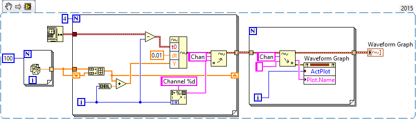
First of all, let me be the first to the congratulate and thank you for finally posting a code! I'm not 100% certain I understand your question or your code, but I have an idea, perhaps, of what you want to do, so I wrote a little VI who made something simple that could be relevant.
You mention waveforms of different lengths and beginning at different times. You also want everyone to have a unique attribute (although I'm not sure what you want to do with the attribute). So, I did the following:
- Generated an array of 100-sample random to represent one second of a waveform.
- Created 4 waveforms on this 100-sample basis. The first waveform (channel 0) is just these 100 points. The second, 1 channel, is the concatenation of string 0 with the base of 100 samples, or a waveform "double". Channel 2 is 1 string concatenated with the base, and channel 3 is 2 string concatenated with the base.
- In order to trace the four channels that they rest 'on' the other, the waveform has the number of the channel added to it. Channel 3 is 3 + (4 copies of the basis of 100 points), a waveform 400-point random centered around a shift of 3.
- All channels have dt value 0.01 (but I guess I could have varied, as well).
- To make the channels start at different times, I started channel N N seconds before channel 0 (by subtracting the index of the loop, I, T0).
- For each channel, I created an attribute called "Chan" equal to "Channel N" (where N = 0, 1, 2 or 3, as the case may be).
This is the plot that results. Scale X is the absolute time value (no Date) using the 24-hour HH: mm
 S format. You can see that the plots are 1, 2, 3 and 4 seconds of time, and are offset from each other by a second. I used the trace attributes to change the name to the respective attribute.
The code to do this is very simple - I almost don't need to show it, because I think it is completely described by the text above, but this is here:
Now, it was not that much faster that some of your previous posts, when you refused to your postcode, "guess us" what you wanted (but not to not correctly guess), you tried to "push" us in the right direction (still refuses to post code), and no one seemed very happy?
Bob Schor
-
Problem when the PWM signal combinning and analog signal TOGETHER!
Hello everyone,
first I DAQmx 6212, and I need to run the water pump small (9V - 16V) that should be driven by a PWM signal; I also have a motor (5V - 13V) for a water supply which must be controlled by an analog signal and it has built in a force feedback potentiometer, I logged onto this potentiometer correction + 5V the DAQmx and used the output voltage of the third extremety as a value to diagnose to know the position of the engine.
My VI shows:
1 is a normal meter production to create my PWMout signal.
2 is an analog input, I use it as a PWMin to the LabVIEW to diagnose what is happenning in my pump water through the cycle and frequency.
3 is an entry of the third extremety of the analog potentiometer.
4 is an analog output that I used as power supply of the motor valve and I used an AC/DC amplifier for aplify signal the DAQmx and the motor road, between the two (3. 4.) I made a comeback with a few calculations, I had a P-controller to know the real position of the engine valve.
My problem:
When setting to 1. and 2. in the same VI only, I get an own PWM output with no problem.
also with 3. and 4. in the same VI only i can control the motor valve without any problem.
but when I put all these 4 set found in the attached VI, I have a problem as the engine valve turn continuously without stopping even if I change the position of the valve between 0 and 100%, I should mention that I see a PWM normal outside a signal on my oscilloscope, another thing to delete one of (1 or 2) and run the engine valve VI works fine without any problems.
so this my problem, if you can think of any solution please let me know.
Thanks in advance for your help.
Kind regards
Caliente
Here's your VI, slightly modified so the two analog inputs belong to the same task. This if only for purposes of illustration, I him have not tested. You will still need to do some debugging.
While changing your VI, I noticed another potential problem with your original configuration. You have configured the two tasks of AI for the same frequency, but read you 10000 samples of one of them and only 100 samples from the other (and throw it most of it). Data acquisition data are buffered, and if you read as fast as you acquire, the buffer fills eventually. If you read 10,000 samples of a channel, and the other channel acquires at the same rate, then when you read from the second channel you will get old stale data or an error full buffer.
Maybe you are looking for
-
Blocker 'exceptions' does not work
I've identified a site for which we should be able to jump - rises. (Homepage of the Multnomah County Library and the library catalogue page.) Details of items on a page of catalog are provided in windows Firefox v. 9.0.1 treats like pop-ups. (Versio
-
Indicator WiFi P70-A-L1M satellite will remain on after the upgrade to Win 8.1
Hello. After update to 8.1 Windows wireless indicator is still on (red light), no matter if the WiFi is really turned on or off. When I press the f12 key, WiFi passes in Airplane Mode, I have a message in Windows, everything is ok.But the light still
-
Laptop HP 15-f010dx: drivers for HP laptop laptop 15-f010dx
Hi all I have a new HP 15 - computer f010dx laptop running Windows 7 (64-bit). Could not find the drivers for the following items: PCI device SM Bus controllers Ethernet controller USB controller The product number is J9M23UA #ABA Kindly help me to g
-
Reformatted and drives disappeared
OK, I recently reformatted my hard drive of my computer. Since then, my two DVD ROM and my slave drive does not appear anywhere. Please help and with laymans terms preferred. :)
-
Why it does not recognize my hardware?
I installed windows xp home edition on a separate partition adjacent to windows professional, why not my house version recognizes all my hardware namely ethernet, network controller, video controller, etc. ?