Will be on a damage of PFI line 24V 9188 chassis?
I expect no trigger for the acquisition of data with a chassis 9188, but I want to use to send the trigger pulse (servo) operation to 24V. This will damage the chassis? Should I step the voltage until the TTL level?
You really should read through the specification of the chassis. If you use a PFI on the chassis, then he can accept up to 25V without damaging the chassis.
Tags: NI Hardware
Similar Questions
-
Is there a screw (2009) which will allow you to access the value on the PFI lines live? See what they are? The wired customer lines PFI to read a logic level under certain conditions.
clint100,
I think that there is some mixup nomenclature, let me give you my point of view to see if that clears up things.
While you can't 'read' the PFI line, it can use an event on this line to trigger or sample (see the link a few posts to the top) to do something, you might be "expecting". I also see why you want to read or query the line to control the flow of your code, if you were on a microcontroller or FPGA you would be wrong. The traditional DAQ or DAQmx driver is more abstract than that and will want to take this entry as a trigger, or a sample of clock.
That being said, there is a bagillion to the examples in the example finder to help you configure that. Otherwise, I may be completely wrong interpret the sentence you put in your message, anyway, good luck!
-
How to set up the PFI lines as input to PXI-6713 module
Hello
I have 6713 PXI module in my chassis PXI-1044. I have configured the PXI-6713 module to geneate some analog signals to my Board of Directors.
Council inturn process this analog signal and answers in return the status signals through a registry to the Board of Directors. In my application, the status bits in the register state of the governing body are mapped on the PFI 0:3 bits of the PXI-6713 (pins 11,10, 42 and 43) module.
My query is how can I configuration lines PFI as 6713 PXI module entries to read these status bits?
May be less than the explanation could give you little more information w.r.to my request.
When I use NI USB - 6008 module to read the same bits, because this unit has 12 e / s digital, I was able able to read the status bits in the last 4 digital lines by setting up those digital lines as input.
In the PXI-6713 module, I have only 8 digital lines. These 8 digital lines I used to send digital signals to the Board of Directors. I find myself with no digital i/o. Therefore, I could not use these digital lines. I'm left with only one option to use. Joana re PFI lines. Also the bits of status in the axis of the room are mapped such that the bits can be read through the PFI lines.
I was wondering do we have any example code to use inorder to read these status bits to the Board of Directors using the PFI lines.
Please let me know if you need more information to help out me.
Thank you.
Hello
When using the PFI PIN as input, you can individually configure each PFI for edge detection or level and the selection of the polarity. This information of PFI are referenced in the manual of Series DAQ Analog Output on page 6-1 (http://www.ni.com/pdf/manuals/370735e.pdf). Unfortunately, the PXI-6713 PFI lines are able to time a signal input and output for functions, AO or counters/timers. The ability to create static DI of the PFI lines is not available for the PXI-6713. However, some cards have this capability. The latest National Instruments products with PFI lines have the option of setting as PFI lines:
- Static digital input
- Static digital output
- Input signal of sync for functions HAVE, AO, DI, or counters/timers
- Output signal of the calendar functions HAVE, AO, DI, or counters/timers
(http://digital.ni.com/public.nsf/allkb/14F20D79C649F8CD86256FBE005C2BC4)
When the static value such as DIO, PFI lines are assigned to a different port (for example. PFI0-7 is Port1). More details on this subject can be referenced at:
http://digital.NI.com/public.nsf/allkb/DA2D3CD0B8E8EE2A8625752F007596E1
http://digital.NI.com/public.nsf/allkb/862567530005F09E8625677800577C27
-
Question about a query that will be 1 for the first 10 lines, 2 for the
Hi all
I am trying to write a query that will be 1 for the first 10 lines, 2 for the next ten lines and so on.
I tried several approaches such as mod, rank, case but could not get the correct idea.
Grateful if someone can give me a hint on this one.
Ex:
Col1 Col2
1 989
1 120
1 876
2 121
2 456
2 87
1 of 3
3 22
3 333
....................... and so on..
Thank you
MK.How about this:
His past all my tests so far
select trunc((rownum - mod(rownum-1,10))/10)+1 from dual connect by level <= 1000 -
I accidentally typed my password at the e-mail address line and now it automatically appear if I press the first character of my password on this line when I connect.
I don't want my password to be seen on this line.
Can I uninstall and reinstall Firefox to fix this?Hello, resettlement will not help in your situation - when the suggestion of fill incremented appears simply select with the arrow keys and delete with the delete button, then it will be erased from the memory-AutoFill in firefox.
-
Maybe I'm missing something, but it seems to me that if I have a style with a parameter 'space before', for example, 21 p, I should be able to put text into a new text box and have this text with the pop of style applied to the bottom of the page. He does not. I can do work just hit 'enter' and by having a blank line in front of it, but in my mind, this should not be necessary. What I am doing wrong?
This is expected behavior. If the text that spans columns or pages you don't want a space above if a new column begins with a paragraph at the top. Like this one, where you want to the 2nd column to align with others:

-
Adobe Reader 11 (XI) will not open the file via command line
Hello
I posted this question , so I am repeating again.
I installed the new Adobe Reader XI today and when I tried to open some PDFs via command line, it reported a syntax error. Now, this syntax worked so far on versions 9 and 10 (I checked today with them and it does not), so my question is - where can I find new syntax, if there are? Google search did not help. Or what else could go wrong?
In previous versions, I was able to open the pdf file (on page 5) like this (everything was taken from the help file 'Open settings')
«Page "/A" CompletePathToAdobeReader = "CompletePathToPDF", 5"»
That is to say
"C:\Program Files (x 86) \Adobe\Reader.
but now - not that it opens a specific page, but it won't open the file at all.
Edit:
Operating systems: Windows 7, Windows XP
Thank you.
Post edited by: v604
Yes, he has correctly reported because there is a syntax error in your order. Try spaces between the /A switch and open the setting. Try this:
"C:\Program Files (x 86) \Adobe\Reader" /A "page = 5" "d:\V2\DataSheet.pdf" "."
I hope this helps.
Sumit-
-
Frequency control of NOR-9476 on the cDAQ-9188
I am using a cDAQ-9188 with a NI 9476 module, and I would like to control the frequency of the digital signals that the module was released. I tried to use the example of Pulse Train digital continuous with control of the frequency, but impossible to select the 9476 since there is no internal counter, and when I change the 'Digital output' task, the frequency control disappears. Is it possible to use the internal counter of frame to control the output frequency of the 9476? I need to get out a range of 0 to 1 kHz.
Most of my program would output a digital signal of a certain frequency every second in real time from a given table. For example, if I have an array of [10, 20, 15, 100,...], it generates a model of up/down of 10 cycles per second for a second, followed by 20 cycles (with a shorter period) for a second, then 15 cycles per second for a second, and 100 cycles per second for a second.
I tried to use avoiding to do, but it was very slow, with a delay of 63 ms between each cycle, when I wanted a 1 ms delay.
CDAQ-9188 has 4 counters built in, but you cannot access it by using the NI 9476-, but the NI 9401 module can access the built-in meters.
The good news is that you can always generate your pulse train, using counters, it generate on the PFI lines on the chassis itself and not through your module. If you need to generate more than a pulse train, or use all four counters, you will need the module NOR-9401/9402.
In order to get the speed, you will need to use the capabilities of hardware counters timing.
I hope this helps!
For more information:
-
How to choose the line PFI to use on the port of the 5761?
I understand that the VIDEO that I use on my DAC 5761 allows me to access 8 PFI lines. However, when I access my 5761 devices in the project window by clicking the "+" next to the name of the module, I see that 'PFI Input' and ' output PFI. I tried to get this to send a signal in the past, but I have been unable to determine how to select the line PFI I want to use. How can I select the PFI line?
Any ideas? I was able to get the my AWG PFI (5422) for work and it is amazing. I want to order an attenuator digital step for a ground penetration radar that I develop.
Your time and your help is very appreciated.
PS: I have worked with this PXI system (chassis, embedded controller, FPGA digitizer 5761 and AWG) for 1 year and I am afraid that it is time to learn this one way or another.

Good day!
-Daniel
I found the solution. In addistion to the node which is visible in my previous post, there must be a node to enable PFI write with an entry of decimal number indicating the line is activated. Then, there must be a node PFI active connector, set to true. Not sure if the node of the latter is really necessary, however. Otherwise above examples should work as is.
-
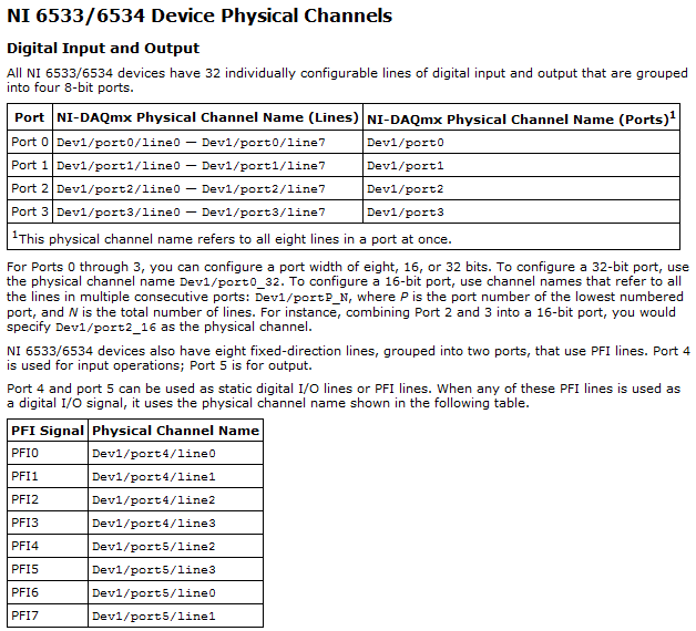
I only need a port of each line for the use of the PFI and want to use the rest for the digital I/o. Before you complete the design of the circuit and test it myself, I would like to check it out. I can't find the answer in the textbooks, either.
Thank you
Ben
Hello Ben,
If you use all the PFI lines you can use the rest as DI/O. PFI0, 1, 2, 3, 8, 9, 10, 11 are entered digital and PFI 4,5,6,7,12,13,14,15 outputs digital. Another technique you can use is to create a spot on the measurement and Automation Explorer, if it allows you to create it, then it is possible.
Best regards
-
Strange white line on screen Equium A60
Does anyone know why a strange white vertical line appeared on my screen A60? We off fragmented, a virus scan and a cleaning disc then the line appeared about an hour after.
That this has something to do with it? Should I install the product recovery disc? We did this a few months back, re - install too often cause damage? The line is present as soon as the screen lights up, i.e. Toshiba start screen.
Any help would be appreciated, thanks!
Hello
first of all, no, system reinstallation will not damage anything.
As you say the line appears directly after start-up the machine, the problem must be hardware related.
Check if the problem is also on an external monitor.
If not, the LCD is faulty.
If so, the problem may be the graphics chip.Anyway, you cannot do anything alone, in order to take the laptop to a service provider.
Good bye
-
PXI5122
It is not very clear if I can do this, but it is
possible to arm the PXI5122 (pending a
external trigger) and a pulse output on
either PFI lines?
The PFI 5122 trigger material ext and
the 5122 will read the result.
I try to use the LOAN to START at EVENT
Which States 'generate a pulse when the digitizer is. "
initiated and ready to start the acquisition to start sampling '
TIA.
Hello
Yes, you can use the niScope export Signal.vi to produce a digital on one of your lines PFI pulse when a certain condition is met. From your post, it seems that you may already use this VI. I have attached a screenshot of the Signal VI export and included context-sensitive help and detailed about what parameters to signal help is available.
-
The value of static output on PFI on USB 6366
Hi all
What I want to achieve is to save dedicated 8 DIO lines on dev USB6366 on port 0 for some specific application and use remaining 16 PFI lines control some external equipment.
All I need is the ability to set some PFI line high/low within a reasonable time by command software (LabView, .net, C, whatever). No requirement special timing, just set some PFI lines high and LOW back switch after not less than 20 ms. These signals would be used to control an external logic; no significant current.
The question:
Is it possible to control the PFI lines in the way that I described on 6366 USB device?Manual for this device (or in fact, the family of devices) is a bit ambiguous on this subject.
It is said it is possible to select 'direction' of each digital line but that's it. No more information. Only a manipulation of the port 0 (general purpose DIO) has its own section. PFI-Out is just mentioned. PFI - In is explained a bit more in detail, but also vaguely.
P.S. I have no devices available now (I would have tested the ability to do what I described, if I had).
Thanks for your time!
Bebor,
You should be able to use the 16 PFI lines as digital lines. To change the status of the lines, you must create a task of digital output, the same as you would on the lines of port 0 (DAQmx manages the programming of the direction of line for you when you create a task). Writing DAQmx can then update the status of the lines.
These lines do not support the operation timed, so lines are updated when writing DAQmx is called. Synchronization restrictions that are imposed should be dealt with by your software and will be limited to the accuracy of the software timers put at your disposal.
Dan
-
How the PFI to go top-to-bottom with sample clock?
Hello world!
I am very new to LabView and I try to do something very simple in the NI PCI-6534 and still not get anywhere (or do not know if it is the limitation of the hardware)
My request is to acquire digital data of 2 channels (16-bit each) of our Board custom designed analog-to-digital.
So far, I am in a position to acquire a finite amount of sampling digital (say 100000) and using a trigger to start (PFI6) to start the acquisition of our custom card board. Just to let you know that I'm feeding the PCI-6534 an external clock of 20 MHz by PFI2.
However, I want to send a signal to trigger recognition (high/low-rising edge) to our personal advice, saying: he did the acquisition of 100000-sample.
My problem is that whenever I try to use the lines of PFI signal with an internal sample clock, I get an error saying that I can't use the PFI lines with any sample clock. But my goal is to use a rising edge (low-high) to trigger back.
So far, I can pull the PFI4 high and used a timer to make it low. But the resolution of the timer is milliseconds (software) range. I would like to have at least a few microseconds.
I also tried using implicit since manual said that it does not require any clock but still get no result. Also, I couldn't find an example of implied clock and don't know if PCI-6534 supports.
Note that I'm able to use the clock synchronization of sampling with other DIO (Port 0 to Port 3) lines and get the result I want. However, I would need to use all our custom Board 32 - DIO for analog-to-digital data lines. So, using the line of PFI laccuse is the only choice.
If you have ideas/pointers, please throw it at me, I'll try them. Thanks a lot for your help!

See you soon,.
Yaseen KhanHi ykhan,
After validation, I noticed that it will not really work for what you are trying to do. The PFI lines on your 6534 are I/O static only as shown in the DAQmx help.
You will be able to control these lines, but only with software timing. You should be able to call and argue by their physical channel name. I hope this helps!
Kind regards
-
CDAQ line internal uses as to task DAQmx
Hello
I have a cDAQ-9178 and I would send a trigger to two different tasks (DO and HAVE) to be sure that they start at this very moment.
I want to pull the trigger using the software instead of and the external trigger on PFI lines for example. For example, I would activate when a user a press control on the front panel.
I tried to use the internal counter of the cDAQ (_ctr0) by producing a pulse on this subject. The problem is that I don't see these online when I'm the trigger of the 2 previously mentioned for task configuration. There are a lot of different line which seems to be possible to take, but I don't know how a trigger on the thesis...
Help would be appreciated!
Thank you!
Is there any installation work you can do before generating a start trigger. For example, create a task, creating channels, configuration of timing and call back to this subject can take a few hundred milliseconds. There are intermediate steps, you can take in front-loading from time to time configuration.
A DAQmx task has a certain number of States. When you call start on a task, it passes through verified, reserved and committed to started. So if you're explicitly your task, your call will be faster because your hardware is already configured. If you had already created the task, created channels, set up the synchronization and committed to the task (via the DAQmx task control interface), the start task could take only 10 ms or more. These numbers are on the top of my head. This will not reduce the time it takes to start your task, only a specific stage of the issuance of your trigger for starting the software.
That said, if you go to the road to counter, you need not to do for your tasks to AI and. Just make sure you start them before your task to counter. You could do what I described above for task of yoru meter if you feel he was taking too much time to generate your trigger to start.
* Edit *.
I should mention that the delay time that I was talking refers only to the time of when your user requests a trigger to start generating chassis a. The time of your trigger from start to the first sample clock in your task is essentially nothing - about 12.5 ns or so depending on your configuration.

Maybe you are looking for
-
What happens to the records staff and old e-mail address book when I change to new email
I got a new email address. I'm going to quit using the former, who was with Comcast when I cancel the Comcast service, how can I make sure that I don't lose my personal folders and the address book. Also, if I can keep the personal folders that conta
-
Laptop does not start after spilled liquid
I spilled liquid everywhere in my laptop yesterday. And now it does not work!The thing is, I could activate it yesterday after I poured the liquid, it seemed ok. So I just turned off and left to dry.But it is not today. What should I do?
-
HP Pavilion dv6-7029wm: BIOS display on an external monitor
Hello The screen of my laptop has been broken for quite awhile now and I tried to find a way to be able to view the BIOS on an external monitor. I tried pressing f2 and f8, f10 or esc on startup and try using f4 to toggle the display without result.
-
Hi guys,. I have 1 x WLC 4402 that control 6 AP-1242AG Wireless, which breaks down for some minutes and will be back to the top and I don't see the newspaper in WLC. What are the opportunities that wireless certification will be 3 minutes and will be
-
Why timelines in Active AND inactive what is the purpose?
Insert a button box or click on and the object appears in the panel mounting with an icon pause in the middle. On the left, the subject is active and inactive right.What is the possible purpose of adding something that is not active?The object can be