Wiring of a NI 9237 and a torque transducer
Dear all
Newbie to these forums and equipment OR in general
I have a module OR 9237 and Labview using 2014. Recently, I managed to connect a couple of load cells to the NI 9237 and VI I built so that it works very well!
Now, I use a torque sensor and I was wondering if the NI 9237 is suitable for my piece of equipment?
I enclose the reference data sheet and the transducer that I have is the RT2A 5NM. There are a few areas that interest me on the datasheet are: (and please be gentl if these are simple assumptions or biases, I do).
(1) the rated power is of +/-10V
(2) the suggested nominal power is 15 - 24V (the NI9237 can provide this voltage?)
(3) the connection of the power cables seems to depend on the power supply voltage to the output voltage? (is it safe for the NI9237)
For point 1 in particular I can't seem to find any calibration for scaling? or are the transducers of torque generally considered a linear relationship between the highest voltage and the highest measure of possible couple?
Sorry if this all sounds pretty basic questions, the 9237 was module quite expensive so don't want to really rely on trial and error to build my next code?
Thanks for reading this post!
Hello world
Just to let you know.
Spoke the manufacturer. It is fairly standard if a transducer unit is already amplified and producing a voltage reasonable result such as + or - 10V. Then, the requirements are that you will ony need a data acquisition scalable to change the voltage in torque values.
In my case the torque-meter has been calibrated at the factory to read up to 5 nm and therefore the maximum 10V output voltage will be the equivalent of 5 nm. The torque/tension relationship is generally linear. So, for every volt should be the equivalent of 0.5Nm. The calbration manufacturer shows that standardized resting voltage is approximately 0.001V.
The voltage is relevant as an integrated amplifier in the sensor so the provider is a little higher than 15 - 24V rather than normal 2.5 - 10V requiring no amplified transducers. The NI9237 can provide a voltage higher than so a separate voltage must be applied. The voltage range is relevant only when certain factors such as the length of the cable and the amount of interference become apparent. As a general rule, use voltage as little as possible is the best that the actual voltage used by the transducer is normally regulated internally so if providing 15 or 24V won't have much impact (except if you have the above conditions).
Hope that helps
Tags: NI Hardware
Similar Questions
-
NEITHER 9237 and SignalExpress
I have a cDAQ-9174 with modules OR 9237 with SignalExpress 2011 for strain gage measurement. After a few problems and doing some research on this forum, I discovered that the minimum sampling frequency for the NI 9237 is 1613 samples/second. However, I need a sample of about 1-5 samples/second rate as my tests will be the order of 4 to 5 hours and record 1613 samples every second will make my too big data file. On the forum, I found these workaround solutions:
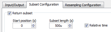
Subset and resampling (http://zone.ni.com/reference/en-XX/help/371268M-01/expresswb/subset_and_resample/) seems to be the most recommended, however I have a few questions about this. I selected a range of subset of 0s to 1s and then choose a resampling of 200 Ms. that seems to be the more manageable sampling frequency, but then I have a problem with the export of the data collected. I get a message that says I can't export to Excel, as the data are 'not continuous' and can only convert to text. However, the text file is not really useful as it breaks down the data in individual games and puts the time in terms of dt. For small sets of data, it seems that it would be possible to manually determine every moment given by point, but I will receive a large number of data sets. I have tried uncheck the "optimize to run once" but still not the same type of data file. What makes a kind of aggrivating, it's in SignalExpress data view tab can display a graph of deformation over time, that I need in Excel.
Another recommendation is to use the 'Statistics' using the collected samples, then changing the number of samples to change the rate. However, I prefer not to use this method because it seems to imply "at x time, average of the latter strain is y" rather than 'x time, strain is there' and I want just the value of the strain at every 0.5 s, 1 s, 1.5 s and so on (although I guess that how that differ from the subset and resample method?).
The last recommendation I found suggested to use an N-sample acquisition, set to read two samples and then set a delay of acquisition of post about 1000 m that would have been a nice solution, but it seems that SignalExpress impossible to compile all the samples to read a log file, that I have seen only two data points when I opened it in Excel.
I'd appreciate any help, thank you.
Hello MAF101,.
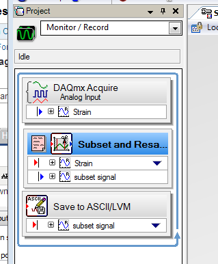
I ran your own project and it worked for me. I just used the following values:
It worked very well, I managed to turn on logging. Then, I tried logging information in a txt file using the instructions below:
I got the attached file below using a relative timestamp. It connected two samples per second.
Concerning
Frank R.
-
Wired Keyboard 600 with slow and some keys do not work when I press them.
I have a microsoft 600 wired keyboard - he constantly young: types, I paid for the download of the driver as I thought that may be the problem, all the drivers are updated, but still get the missing and also slow to react on the keyboard, I think scrolling is very hit and Miss ideas
Original title: keyboard continually for young
Hello
Did you of recent changes to the computer?
I suggest to follow the steps mentioned in the article.
Troubleshooting: keyboards
http://www.Microsoft.com/hardware/en-CA/help/support/troubleshooting/keyboard/common-issues
Mouse, touchpad and keyboard with Windows problems
Hope this solves the problem. If the problem persists, you can write to us and we will be happy to help you further.
-
1. I can ping computers by IP address and name, but I can't access the shared folders on the desktop to the laptop.
2 working group is set up on both machines with the same name.
3 McAfee and win firewall is turned off both for troubleshooting purposes.
4. from office network places, it shows files from the laptop. The laptop computer, the desktop computer is not seen.
5 hot fix for XP machine, Layer Topology Discovery LLTD (Link) (KB922120) answering machine will not load on the desktop with XP SP3.Hello swindco,
Have you tried to change the wireless channel that your router is running at? There may be interference that could prevent the network connection:
Take a look at step 6 in this article that give more details about it:
http://www.Microsoft.com/athome/Setup/wirelesstips.aspx
If you need assistance to change the settings of the specific router, you will need to contact your router manufacturer or your internet service provider.
-
Connection keyboard and mouse USB Wired stall
Hello
My computer repeatedly interrupts the connection to my Wired USB mouse and keyboard. Usually around one every 30 seconds, the connection falls for 1 to 1.5 seconds, then comes back. Meanwhile, the cursor hangs - I can't click anything, and I can't press any keys on the keyboard. For example - when I type, I have my keyboard will stop working for a while, and no text will appear. This is particularly problematic when I play games.
I tried to reboot the computer, reset the SMC and the mouse and keyboard. I also tried all USB entries on my mac (4 in total), and the problem persisted with each of them. This leads me to believe that it is either a problem with all the USB inputs, or a software problem.
I have an iMac 27 inches, mid-2011 with OS X El Capitan 10.11.6 (specifications: 3.4 GHz Intel Core i7 processor, 16 GB with 1333 MHz DDR3 memory and storage capacity of 2 TB).
I use a wired USB (Logitech G402) mouse and keyboard USB Wired (Razer BlackWidow Stealth). I have the latest version of Logitech Gaming Software and Razer Synapse installed for support.
I would appreciate help.
Check if there are updates available driver.
To check if the problem is with the USB to your Mac controller, test with a different keyboard or mouse.
To check the extensions conflicts, etc., try the startup mode.
-----
Restart in Safe Boot mode by holding down the SHIFT key at startup. Secure boot is quite slow because the operating system performs some cleanup and verification tasks, so give it time. Once you're completely connected, restart normally.
-
Download speed slow r7000 (wired and wireless)
I have the R7000 for about a year now and originally, I had the good download and upload speeds that corresponds with my ISP rates.
Right now my ISP (cable) delivers 120 Mbps down and 12 Mbps to the top.
However, I read an article on a website it my ISP would start by increasing the speed down to 150 Mbps and that in some areas what was already available.
That of why I unplugged my modem and plugged again after a 2 minute order to restart/reset and hoped for greater speed.
When I used several speedtesters (speedtest.net, my ISP speedtester, speedtest.nl, etc.), all came to the same result, approximately 90 Mbps down and 12 Mbps to the top.
Yesterday, I did the test on 2 separate wired computer (HTPC and desktop).
After connecting my HTPC directly to the modem and the test I got good publicity (120 Mbps down) and 12 Mbps speeds upward.
Therefore, it is certainly connected to the router.
Today, I also tried by Ookla's speedtest.net on my S5 Galaxy with 5G wireless and got the same bad results as with the wired connection (90 Mbps down) and 12 Mbps up.
I am also on a channel that is not occupied by another user.
I also noticed that the firmware version higher on the R7000 support site is 1.0.4.30, but when I look in the upper right of the router web INTERFACE it shows the version of the firmware V1.0.5.48_1.1.79.
How is that possible?
In addition next to the Advanced Settings tab, there is a message that a new firmware is available.
When I click on this message the router tries to connect to the server to download the Netgear firmware, but after a few seconds it told me that there is no new firmware available.
I read here on the forum of others with similar problems and tried to revert to a lower firmware version.
But I could not find an answer to this version referred to a firmware that works best.
My questions:
(1) what would be the first thing to try?
(2) when to return to a previous firmware, what is the best firmware choose?
(3) what is the correct procedure for the recovery of firmware?
P.S. for your upload and download QoS information is always off.
Indeed, the RAM has solved the problem.
P.S. I accidentally marked the answer of Tarund as the answer to my question.
Can you please remove that?
-
CAN you have both wired and wireless enabled on HP Officejet 6500 CN557A
We have an internal network where our HP Officejet 6500 is connected and working.
We also have public wifi we would like the printer to connect to, so we can have clients to connect to public wifi and print to the printer.
Box wireless and be active at the same time on this printer (and other Officjets with similar capabiltiies)?
Greg
Hi myitanalyst,
JO 6500 supports one 1 type of network connection is to say either wired or wireless, but USB and network can be connected at the same time
ex: USB + Wired or wireless + USB.
-
Can wireless and wired network connections to co-exist on the same pc?
My new desktop pc of Windows 7 has a Wireless N adapter, but given that the router is located next to I prefer to use a wired connection. When I enabled both, I noticed that the pc was connected wireless, so I disabled the wireless card and connected via wired LAN.
I was wondering if there is any way to keep active both and put in place for the wired connection is a priority, and the wireless connection is used automatically when there is no wired connection?
When more than one network connection is available, Windows uses the one with the lowest metric value. By default, it automatically assigns a metric value based on the rated speed of the network connection. For more details, please see an explanation of the routes Internet Protocol Automatic Metric feature .
To force Windows to use a specific network connection, assign a metric value to each of them, giving the lowest value to the desired connection:
- Press the Windows key + R , type ncpa.cpl in the box, and then click OK .
- Right click on the desired connection.
- Click on Properties > Protocol Version 4 (TCP/IPv4) Internet .
- Click on Properties > advanced .
- Uncheck Automatic metric .
- Enter a number between 1 and 9999 for the Interface metric .
-
Airport Express, Time Capsule and Airport Express using the same network
Just moved into a new House and this is what I install. I have 7 Port wired into the House.
Closet of network in the Garage:
- Cable modem
- Airport Express
- netgear switch 8 ports
- It works pretty well. All my wired connections work fine. Wireless is quite good but cove not enough of space in my house.
Think about adding my airport express capsule of time in my office - plugged into one of the hard wired connections. Who works AND let me wish the WIFI?
Thank you!
Yes fine, assuming that first test you the Ethernet port in the office by connecting a computer (with WIFI disabled on the computer) using a spare Ethernet cable runs to ensure that the computer can get a good connection in this way.
Put the airport Time Capsule to create a wireless network that uses the exact same wireless network name and password in your existing network. Apple installation "Wizard" automatically configure airport Time Capsule in the correct setting of the Bridge Mode for the device.
-
You try to run the scan mode and mode interface fpga at the same time is causing errors
I'm reading a 9236 9237 and a 9215 with the scanning engine and read from two 9211 modules with the fpga. It's because I need to acquire to 200 Hz with the 9236 9237 9215 but maximum rate of the scan engine is limited by the slower module in the system, which in this case is the max of 15 hz the 9211.
So to use both interfaces (scan engine and fpga), I followed the percisely given in this article for instructions.
1. the project has created and added the peripheral crio using the interface of the scan engine.
2. Add the target fpga and drag and drop the 9211 inside modules
3. has created the fpga in interface file with and compiled with no error.
4. interfaced with the file fpga at almost exactly the way the sample project of "getting started with 9211' by using the engine of analysis in the interface with the other modules.
5. after the errors to discover that I created a VI that tests for just the portion 9211 code (called "thermocouple FPGA method Test.vi")
The data returned by the interface fpga was nothing else than zeros on all channels, even if thermocouples were hooked on some of them. (all zeros as entries in the convert temperature vi gives-410, 6160 degrees F, if you happen to have the material to try this.)
I get the following error from the open fpga vi reference:
code error-61141
"Thermocouple method Test.vi FPGA.
Activities FPGA:Open FPGA interface reference.
Reserved outside LabVIEW FPGA: turns The RIO Scan Interface. You must set the mode Interface FPGA chassis in order to unlock the FPGA. »It's extremely frustrating, because as I explained, I've been very attentive not only follow the instructions for concurrent fpga and analysis but also to model my VI by the example of VI, even if only for the moment, just to try to work things out.
Any help would be appreciated as I need to fix this for the further development and I am somehow in a lack of time. I opened a support ticket (reference #7256226), but the app engineer had no time to answer.
My system:
cRIO-9014 controller RT with crio-9104 bottom of basket.
LabVIEW 2009
Latest drivers and peripheral software pc and rio (RIO scan 3.2 engine support june2009)
rex1030 wrote:
I'm reading a 9236 9237 and a 9215 with the scanning engine and read from two 9211 modules with the fpga. It's because I need to acquire to 200 Hz with the 9236 9237 9215 but maximum rate of the scan engine is limited by the slower module in the system, which in this case is the max of 15 hz the 9211.
This should not be the case. 9211 data will not update with each sweep, but you should be able to run the scan faster than 15 Hz without problem. Do you have specific issues with this?
So to use both interfaces (scan engine and fpga), I followed the percisely given in this article for instructions.
1. the project has created and added the peripheral crio using the interface of the scan engine.
2. Add the target fpga and drag and drop the 9211 inside modules
3. has created the fpga in interface file with and compiled with no error.
4. interfaced with the file fpga at almost exactly the way the sample project of "getting started with 9211' by using the engine of analysis in the interface with the other modules.
5. after the errors to discover that I created a VI that tests for just the portion 9211 code (called "thermocouple FPGA method Test.vi")
You can try making sure that the chassis is set to mode Interface FPGA and the setting is deployed. I wrote that article that you referenced says will select the deploy option later and not explicitly speak to deploy the chassis later. Run a VI with a reference open FPGA vi not automatically deploy chassis settings if you need to do it explicitly. Try the following steps.
1. right click on the frame element and select Properties. Make sure that the Interface FPGA option button is selected. \
2. right click on the frame element and select deploy.
3. repeat your VI.
The data returned by the interface fpga was nothing else than zeros on all channels, even if thermocouples were hooked on some of them. (all zeros as entries in the convert temperature vi gives-410, 6160 degrees F, if you happen to have the material to try this.)
I get the following error from the open fpga vi reference:
code error-61141
"Thermocouple method Test.vi FPGA.
Activities FPGA:Open FPGA interface reference.
Reserved for LabVIEW FPGA outside: The RIO Scan Interface is running. You must set the mode Interface FPGA chassis in order to unlock the FPGA. »The likely cause of this error is that the setting of the FPGA Interface on the chassis has not been deployed. If the chassis is still Mode Scan fixed personality bitfile will be loaded on startup and the FPGA will be locked.
It's extremely frustrating, because as I explained, I've been very attentive not only follow the instructions for concurrent fpga and analysis but also to model my VI by the example of VI, even if only for the moment, just to try to work things out.
I'm sorry that you have had difficulties. Assuming that I'm wrong about the source of your problem, it seems we have to update less than Ko to include the deployment step.
Any help would be appreciated as I need to fix this for the further development and I am somehow in a lack of time. I opened a support ticket (reference #7256226), but the app engineer had no time to answer.
My system:
cRIO-9014 controller RT with crio-9104 bottom of basket.
LabVIEW 2009
Latest drivers and peripheral software pc and rio (RIO scan 3.2 engine support june2009)
-
Synchronize the pci-6254 and cDAQ-9174
Dear all,
I hope you enjoy!

I intend to synchronize two cDAQ-9174 chassis for an application where I need to acquire data of 8-Thermocouple, voltage 3, 1-Full bridge (strain gauge) and channel 2-meter at the same time. This enforcement action is based encoder (quadrature with 1024 ticks per round) and I need to acquire data very fast and synchronized in all channels!
I bought the material and I'm going to set up 3-voltage channels in NOR-9221, Thermocouples-4-NOR-9211, 1 strain of NOR-9237 and 2-meter gauge in NOR-9401 first cDAQ-9174 chassis Modules. I will then put remaining Thermocouples-4 in the second cDAQ-9174 chassis.
The question is whether it will work?
If Yes! Then, kindly help me on how to have synchronized it data from these two cDAQ-9174 chassis with all such modules as mentioned above?
I hope someone can help me with that and can guide me to do this task! I'm using Labview 2009 with NOR-DAQmx 2009
Kind regards!
Tajim!
A few comments after looking at your code:
I don't understand what you're doing with cancel in the task of counter.
You try to use the encoder as your sample clock? You can do it for the module 9221 and NI 9211, but it will not work with the NI 9237 as I mentioned above. You can move the NI 9237 in a separate task and from there, you have a few options depending on how you want to synchronize.
How many times you expect to get your clock on cDAQ2Mod3/PFI0?
-
Conversion gain proportional and derivative to significant stiffness and damping units PID
Hi all
I appreciate if someone could give some insight on how to convert the proportional gain (Kc) and secondary gain (Kc * Td/Ts) in meaningful units in terms of stiffness(Nm/rad) and damping (Nm/rad.s)
I do a position with PID (FPGA) .vi control... I only perform a check of the PD.
My process variable is the position of encoder in charges.
Thank you!
PS: To make things more confusing (for me), these gains are represented by a number fixed point in the express PID (FPGA) .vi and they are normalized too.
Hi Nathan,
Thanks for your reply. I gave her a reflection more and that's what I found.
My process variable is the location information of the encoder, which is the unit of account. My controller, multiplies the P position error, more the rate of change of position time D and it sends to the engine as a control voltage. It is:
output of the PD controller = control voltage of the motor amplifier = P * (Pos (setpoint) - Pos (process variable)) + D * d (Pos) /dt
So my P gain has the unit of volt/count. To convert this to N/m or (Nm/rad), I need to know what the relationship is between 1 volt for the engine and the torque generated (1 volt = 1 * K1 amp = 1 * 1 m end * K2 Nm). I also have calibration, namely the relationshio between 1 County of the encoder and displacement of end effector (1 count = K3 * rad)
Knowing these values K1, K2 and K3, I can convert my P gain to a setting of significant rigidity in terms of N/m or Nm/rad for the torsional stiffness. Similarly, the D can be converted into a unit of depreciation.
It's my understanding. If anyone has a comment on this approach, I am happy to hear it.
See you soon!
-
9237 & 9205 with 9178 chassis sampling rate problem
I have two 9237 and installed 9205 on 9178 chassis. In order to acquire data at the same time, all the 9237 and 9205 use the 9178 chassis onboardclock. But when the sampling frequency is 20000 Hz, 20000 points just takes less than a second. When the sampling frequency is 10000Hz, get 10000 points takes 1 second. Why does this happen?
A 9237 use a channel, another 9237 use 4 channels, the 9205 use 3 channels (differential). And manual brand 9178 slightly confused me, the frequency of onboardclock MHz 80?
Looking forward to your help. Thank you.
By default the 9237 derives its clock dividing down from his own time of 12.8 MHz (see specifications) base.
12.8 MHz / 256 / N
Where N is a whole 1 to 31.
10 kHz is achievable (12.8 MHz / 256 / 5), but it's not 20 kHz (12.8 MHz / 256 / 2.5).
The driver will round up to the next frequency, which is be of 25 kHz (12.8 MHz / 256 / 2). 25 kHz, we would expect 20 k samples to be acquired in 0.8 seconds.
Best regards
-
How to record data every second and present them in a table
I got a set of data of an instrument and the acquired data to an AI, and I want to compare them in a table.
Position of time (from AI) frequency (from Instrument) value of Q (of the Instrument)
0.00
0.10
0.20
0.30
In the future, I want the table excellent export file.
Could someone help me with it?
No, you don't understand. If you have a flag outside the while loop, it will be not updated before the end of the loop. It must also ensure that the data type is correct when you move outside of the loop and I don't think that you did exactly what meant Dominic. I suspect that you wired out of 2D data, and that would be a mistake.
Below is a simple shift register to create the data for the table.

You should also check the free LabVIEW tutorials.
-
You can use NI 9237 for the LVDT readings
Dear comrades,
I wonder if I can use NI 9237 and NI 9945 to get the reading of an LVDT. The interest is to measure the movement using Solartron DC Miniature LVDT.
In our laboratory, we have NI 9237 and NI 9945 and I would get your advisor if it would be good enough to measure the movement of an LVDT.
Thanks in advance.
Hi Gtharm,
For the Solartron DC Minitature LVDT transducer already includes oscillator, demodulator and filter which alow the sensor to accept the input voltage and provide a DC output from the position. Therefore, instead of using the bridge according to the measure such as the NI 9237 or NI9945 modules, you must only input I take the input voltage.
The LVDT voltage range would determine which modules HAVE you need to take the measure. Of the specification, you need to at most 100 Hz to get the signal from the probe safely.
I hope that this help mate.
Maybe you are looking for
-
I installed the version 9.0.1 v10 Firefox has crashed maybe 20 times since then. The previous version almost never crashed AND it changed as if by magic of my network connection settings. disable/change actually my DHCP-J' I disable all my Add-ons an
-
I lost my recovery disc and additional software, how do I get a new copy of the CD
-
Cannot start the Satellite L730
Hello I just bought a new laptop (satellite L730) and according to the instructions, I tried to follow the 6 steps of quick installation included in the instructions. After having turned it on, was asked to choose a 32 bit or 64 bit OS (I chose 64-bi
-
Satellite L750: bootmgr is missing
Hello You just bought a L750. When installing, I turned off the computer... Stupid, I know.Now, whenever the computer starts, there is a "BOOTMGR is missing".Press Ctrl + Alt + Delete to restart» What should I do? I am on Windows 7, i5 core from inte
-
PS6500e Firmware 4.2 upgrade path and best practices
recently took on the administration of a PS6500E 1 42 to disks, M1000, PC6224, these units have sat unused for several years. ~ 5-8, I don't think that it was already in use! Time was limited to undertake this task, however, I have downloaded and re