2D raster scan photon counting optimization
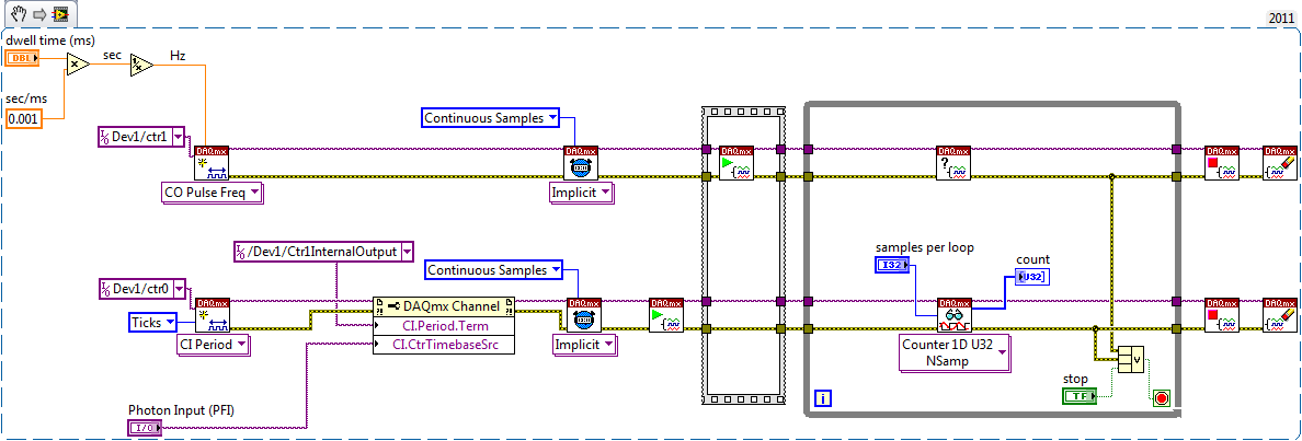
I wrote a VI for a scan 2D raster and pulse TTL of a photon counter to each pixel.
It seems to work very well and is to serve its purpose for now. However, there is something I want to improve
Currently, I have 2 loops, following the breast of one for each of the axes (x and y) for analysis. Then in the inner loop, I count the pulses. Now the problem I face is that I did not understand how to start the counter from 0 to each iteration. Instead, I do turn the meter twice in a for loop and the output of the difference between these two iterations using shift registers.
I want to do is not have to count it twice for each iteration. I tried the task start and stop vi, but they seem to be doing nothing.
The other thing that would be nice is to avoid loops. I heard that it is "expensive" to use loops and cause some general time in the program. I really don't think it bothers me at this point, but I think that if I do the scan rates more quickly then it might. I am currently scanning > 100ms per pixel.
(And also, for the record, my wavefrom raster is slightly different in that in is a 'triangle' instead of. saw-tooth that it goes to the end of the fast axis, then begins the following line at the end rather than the beginning to avoid sudden jerks in my gear.)
I enclose my VI. Thank you
Aditi
I can't help with your meter problems.
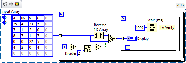
The loops have some overhead. It is the order of a few nanoseconds. Then the loops are probably a little slower than for the lines because of the additional test. Compared to your DAQ timing the time loop is totally negligible. Look at the below test program.
As you know (or can calculate) the number of steps, for loops is probably the best choice. I think that the conditional for the loop is available in LV 2011.
You probably need to move channels AO create screws and clear Associates screws task outside of the loop. Connect the wires to the task via the shift register ID so that the value will be passed in the event where someone enters the start and end values that lead to zero iterations of the loop.
Usually to speed things up you want to (indicators) out of the loop when it can be done without harming the feature all the calculations and display. For example, the division by two can be moved to the outer loop; the entries do not change in the inner loop. If you do not need to see every update immediately, reducing the number of writes to the curve of intensity amy speed up things a bit.
Avoid the right of left child and behind other objects. These have no effect on the execution of the programme, but they make it much more difficult to understand what is going on and the problems of fine. I have attached a version purified to the top of your program.
Lynn
Tags: NI Software
Similar Questions
-
Photon counting using Photon unique cash Module and PCI-6602
Hi all
I am currently working on program couting of photons using a single (Excelitas) and PCI-6602 photon counting module connected to the BNC-2121.
I took a glance at other positions, but I still couldn't solve my problem (or, again, I'm not sure if yes or no, the problem is the specification of the material).
In the program, I'm generates a trigger to 1 MHz pulse using a trigger in a separate loop.
Other than that, I have loops of the producer-consumer model to get data and do a simple subtraction to calculate the number of photons in 1 microsecond.
According to the values connected to 'Input.BufSize' of buffer DAQmx and "Samples per channel" DAQmx calendar, I could change the loop number that the program has done its job correctly.
With the values, the program acquires photon 1 MHz with signls for 139 times.
After that, the program stops and the loopback number increases very quickly.
When I forcifully took stop the program, while the loop number increases very quickly, the program appears "error-200141".»
The error that says "data has been replaced before it can be read by the system." Mechanism of data transfer is interrupted, try to use DMA or USB in bulk. Otherwise, divide the input signal before taking the action. "even if the meter explicitly works in DMA mode by using the sample clock.
I wonder there is nothing that can solve my problem or even the only solution will buy a better Board of counters/timers.
Thank you all for reading this.
I will be very happy with any index

Kind regards
Myeongsu
Yes, the same thing happens on my system.
It does not happen with PCIe-6612.
I found more strange things:
When I start to reduce the frequency at a time given (800kHz) can fill the buffer, it will not start since the beginning of the buffer. He can go to the beginning of the buffer only at 100 kHz for my PC.
Options to fix:
(1) PCIe-6612. Seems to work. I tried streaming at 10 MHz, 5 min - fine.
(2) reduce the frequency of the pulse. If your laser supports 100 kHz, you're fine.
(3) put in place additional synchronous counter at 100 kHz. Basically, it's material average number of photons by 10 pulses.
(4) read 2 adjacent pulses each 1/50 kHz - then your data transfer will be 100 kHz and you will get the number of photons of this impulse of the 20 - th.
Programming issues:
(1) remove the display of the received picture, make only the processing of data and show results if you really need it.
(2) clock.vi sample sets the buffer size, if you specify the size of the buffer, do this after this vi.
(3) I deleted unnecessary "loop generation." He is running on the hardware and stops when you stop it - after reading the loop ends.
-
Helps the acquisition of photon counter data using LabView 12
Hey all,.
Student graduate Chemistry here new to LabView and are looking for some help moving in the right direction. I'm looking for help with connecting my meter to 12 LabView for data acquisition of trace-fluorescence photon PerkinElmer SPCM-AQR-14 (now owned by Excelitas Technologies). I just want to be able to acquire number of photon counts vs. time. Currently, I installed a PCI-6601 and use a BNC-2121 to connect the BNC of the sensor output. The detector has a pulse output digital TTL with 30 ns pulse width, and by contacting technical support on this issue, I was told that this pulse width was too short to always detected by the 6601, but can still go ahead and give it a try. Basically, if everyone is familiar with how to start with this configuration, ANY help would be greatly appreciated. As I said I'm all new to LabView and am currently spend all my spare time reading manuals and help files.
Please let me know if you need any kind of information to make me understand what I'm doing.
I would say something like this:
A measurement period the registry account out of the entrance of the samples as well as gives the meter. You will basically measure the 'period' of your sample clock fixed regarding ticks of the external photon signal.
According to the downtime, you may need to re-read several samples per loop so that the software can keep up with the incoming data. Also, the first sample is not useful because it represents the County between the software from the task of entry of the meter and the first clock signal - you should disregard/erase the first sample (or if you want you can set up a trigger to begin arms).
To do the same thing by using an edge County task would require using both the sample clock AND a counter reset signal - this not is not supported on 6601/6602 (even if it would be possible to set it up that way on a device of STC - 3 as a series of X).
Best regards
-
display raster scan of the 2D array
Hi all
I am very new to LabVIEW and I was just wondering how to make a raster scanning of a given 2D array.
Normal passage of table 2D via loops nested sequential indexing results and show items on an indicator gives 1st line column 1 in the end... 2nd row column 1 in the end... so now.
But I want to get: 1st line column 1 in the end... end of col 2nd at 1... 3rd line column 1 in the end... .so on. (Type of raster analysis)
All ideas in this direction?
Thank s in advance
..............
Manish
Hi do you want?
-
Hello
I am trying to create a LabVIEW program that controls two bipolar motors to create a raster scan. I use DAQmx and Labview 2012 SP1 with a usb 6008. I got the engines to move in one direction, but when I try and get them to move in another direction in a separate task, I get an error-200088 code indicating that my task is not valid. This happens at the beginning vi to move the motor x in the opposite direction of the task.
The logic underlying the program is as follows:
1. move the engine x a certain number of steps to the right
2. move the engine are a number of steps down
3. move the engine x the same number of steps as 1 to the left
4. get off the engine is the same number of steps 2
5. repeat
I can get the steps 1 and 2 work but I have problems with step 3. I use a stacked sequence to show the task for each step.
I appricate all the advice on this topic as part of a final year project
Thank you
Aoife
You can solve this problem very simply. Move all DAQmx departure calls happen * before * the structure of sequence rather than inside. Similarly,.
move all calls to DAQmx Stop and DAQmx Clear happen * after * the structure of sequence rather than inside.
I would sequence the DAQmx Write calls to write the bit of direction * before * writing the bit clock. And I highly recommend that wire you
to the top of your tenants error and outs so you can be informed of any errors in the DAQmx tasks.
-Kevin P
-
Photon counting using the FPGA of the series R. problem generation TTL signals
Greetings,
I try to use the R series FPGA to read and count the pulses TTL of a discriminator (count of photons of the Hamamatsu C9744 unit) connected to a PMT (Hamamatsu-H7422P-40). The release of PMT looks fine (signal.png H7422P-40) but the discriminator wasn't able to generate corresponding TTL 5V pulse. There was some scattered and random spikes, but nothing significant. Instead, the only stable the PMT signal is a single + 5V pulse no matter how, I adjusted the PMT (C9744 output.png) control voltage. The PMT and the discriminator is connected by an ordinary BNC cable 50 ohms.
I am really confused because it was supposed to be a really simple installation. Anyone have a similar question or have similar Instrumentation (but no problem) configuration? Comments/suggestions are greatly appreciated.
Thank you very much in advance!
Hi Kelli,
Thanks for your help. Sorry it took so long to get back to you.
I actually found the question. The discrimination of the Hamamatsu unit level is set too high that all signals got filtered. After adjustment of the threshold of manuallyt, I was able to get the camera TTL pulses. And 7842R worked correctly for count impulses. Everything works fine now. Thanks again for the input.
-
Detection of pulse NI 6259 photon counter min
Hello
I have a PCI 6259 DAQ card which I use as a counter. Is there a limit to the minimum pulse width it can count all operating as a counter? My meter of photons gives the TTL pulses with widths of 50ns which I think is less than what the meter may read unless I'm mistaken. I use 100 kHz as the clock source internal clock. Is there anyway to get the counter to pick up these small impulses?
The NI PCI 6120 DAQ card would be a better choice for this kind of measure? I should be able to get my hands on a bit of time.
Thanks for your time,
Select this option.
Well I just learn something new, I didn't realize earlier that the time base of 100 kHz could serve directly as a sample clock for the tasks of counter as described here.
The task of the meter must be able to count incoming edges at rates well in a few tens of MHz. If you stop the recording of managers when your fn Generator hits 1.5 MHz, I bet it's because the impulses become too round or too low in amplitude to be recognized as transitions TTL.
Try to insert a property node DAQmx channel between the creation of the task and start. Select the property "Counter Input-> edges of the County-> input terminal". Make a writable property and create a constant connection. Right-click the constant, select "Browse...". "and choose the 20 MHz or 80 MHz time base. Run it and check that you get always 200 or 800 counts per interval.
If using the internal time base works as expected, you will need to put emphasis on the integrity of the pulse of your fn generator and your real instrument.
-Kevin P
-
How can I check if the counter entry is synchronized with the analog output?
Hello
I'm working on an application for counting photons. I use two channels of analog output on a PCI-6713 card to send a frame model to a set of XY scan mirrors. I then a photon count unit that emits a TTL signal when the photons are detected as a result of this raster analysis. I then use a surfboard USB-6211 to count the edges on this TTL signal.
I have problems that seem due to synchronization problems. I use the sample AO on the PCI-6713 card clock like the door of my meter on the map USB-6211. I use a trigger to start digital to analog output and a trigger of arms for the entrance to counter early. Is there a way to check that the analog output and counter entry of start of operations at the same time and are are synchronized? I basically want to monitor and compare the ao real sample of the PCI-6713 card clock door signal used by the jury of the USB-6211. I was able to export the sample AO clock and watch it on my oscilloscope, but not the signal from the door of the USB-6211.
Thanks for your help,
Brian
Update... It turns out that there is no problem of synchronization between my meter input and the analogue output. There was a difference of impedance when I connected my unit of counting photons to my USB-6211. This caused an error variable count rate. After accouting for this shift, the problem disappeared.
-
Multichannel synchrobized meter output daqmx c#
Hello
I am facing the following problem:
I'm a piezocontroller operating to move a microscopic sample. The piezo allows me to scan XY of the sample areas. At each position analysis (to each "pixel"), I count photons for the image of the sample. Photon counting is a simple measure of pulsewidth and isn't important here.
What is important is that I have two types of piezo controllers in different configurations. A controller is digital and I can send the coordinates of the area to be scanned. The controller then allows me to define 4 output triggers to synchronize movements piezo with other operations such as opening and closing of shutters, photon counting after each pass of the step to a new position etc...
However, the second controller is an analog that only allows me to adjust the tension to move the scene. If I want to recreate the functionality of the digital controller I need to create four trigger lines myself.
So, my solution should look like this:
(a) I have a "clock" that ticks with a cycletime of 200 microseconds. At each tick of the clock tension in my piezo for X and Y motion are incremented. Master clock ticks are also triggers for the photon counting tasks at each position.
(b) the firing in four, used for various purposes, should behave as described in the two attached screenshots (pictures say more than 1 million words!). If for example it takes 1000 the master clock ticks to complete one scan line, then the line 1 trigger should for example be placed high the first 500 ticks, trigger line 2 should be high ticks the next 500 while line 3 trigger must be high all the time. This behavior must be repeated each line scan etc etc...
Is it possible to have this kind of coordination between the output of 4 meters to say, an edge of 6601?
Any help would be greatly appreciated!
-
Change to error in the export file in the order of the elements in the array of construction
Hello world
Some time ago I wrote a vi file that performs the following operations:
As a first step, it initializes a camera and chooses a region of interest (ROI). Data on the return on investment will be eliminated.
Then he raster scan engine stage in x and y axis, in bidirectional mode (meaning that x alternating between sweeping left to right and from right to left as is inreased).
For each point of the analysis, the spectrum is collected, which is then integrated into lambda to give an idea of the total intensity.
Then the intensity is plotted, as well as the spectrum at each point.
The final results are exported to a text file.
The problem:
If I reverse the order of the son in the 'build' table prior to exporting the file, place the Total Count (intensity) wire instead of thread of the spectrum, the export file fails. By "fails", I mean it's the .txt file contains characters that resemble Chinese!
Why is this?
I enclose my .vi, as well as two screenshots that show the problem.
Hooovahh wrote:
Such a small change, should not have such a strange result. I advise to use some debugging tools like highlight the enforcement tools, probe and breakpoint to see what data is when it runs.
The Source is in 2011. I see an opportunity and a potential work around certain things to try.
- take the following steps
- Select each stacked sequence right click and "convert flat sequence.
- Select each flat sequence and delete the sequence
It could simply fix it by itself you want to turn auto-growth on surrounding structures
2 allows to observe the data in the table build
- For all wires that are sgl heading construction table insert a dbl and a copy of Allways
What I suspect LabVIEW is incorrectly re-use of buffers for the inhabitants of sequence
-
How is there is some noise in the library module, while there is none in the develop module?
Straight, simple like this:
I shoot with a 5 d MARK II. Complete captor. No noise even possibel to ISO high.
I airbrushed a picture and I pushed some limitations while using the tool brush on some sections of the image.
As I watch in the DEVELOP module, I see no noise at all. As soon as I open it in the LIBRARY module, I see the noise on this specific section of the photo.
How is it? Will there be a compression of the image between the DEVELOPMENT and the LIBRARY module?
What to trust? How can we work with divergence like that?
If anyone noticed something similar, I would really like your opinion on this.
> I'm shooting with a 5 d MARK II. Complete captor. No noise even possibel to ISO high.
You have been deceived by the marketing. All cameras, even a 5DmkII a noise at each ISO setting. Most of the noise from digital in modern cameras capture is caused by photon counting statistics (i.e. photographed fish noise or noise) and in small part by the noise of the amplifier. This means that any pixel noise is practically equal to the square root of the number of photons counted by the pixel. "Canna change the laws of physics Cap ' n."
> I've airbrushed image and I pushed some limitations while using the tool brush on some sections of the image. As I watch in the DEVELOP module, I see no noise at all. As soon as I open it in the LIBRARY module, I see the noise on this specific section of the photo. How is it? Will there be a compression of the image between the DEVELOPMENT and the LIBRARY module?
Development module working on a small subset of the raw data for its display, especially when zoomed out to go up or fill. This is to ensure that cursors are sensitive and you don't have to wait for a few seconds each time you touch a slider. You can only trust the preview to establish in what respect the sharpness and noise when zoomed to 1:1 or higher because of this and this means you must be able to optimize the sharpness and noise while the zoom 1:1 reduction. This is necessary in all cases that capture sharpening and noise reduction work at the pixel level. In the library, the preview is a JPEG, pronounced on the raw file using full raw. Also note that if you brush positive clarity, one tends to amplify really no noise in the image, so, be careful and check regularly at 1:1.
> What to trust? How can we work with divergence like that?
1:1 Preview to the point or the glimpse of the library if you are interested in the features of sharpness and noise.
> If anyone noticed something similar, I would really like your opinion on this.
You are not the first to see it for sure. Usually, it doesn't matter except when you push your images really hard.
-
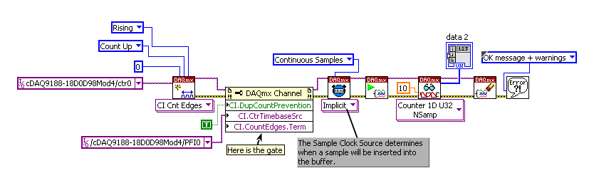
County of gated cDAQ-9188 edges with NOR-9402
Hello! This discussion is a branch of it.
Shortly, I want to count the random impulses of a meter of photons, which emits pulses that when her door is activated (and this should be done in a manner expected by HW), only when the door is active.
I separated this task in two: in timing HW emit pulses of door and to count the edges when the door is active. For the second task, I created a VI:
those who are more experienced could please tell me, if I do it in a right way? I'm a little confused on how to connect my device: random TTL of the photon counter should go to ctr0 PFI0 (in NOR-9402 this is the PIN 0) and what I generte of the first task (in fact, pulse clocked by HW) door and then must be connected to the terminal of the door of my meter (left unwired above) both at the entrance of the gate of the photon counter... There must be a mistake in the present, I guess that (otherwise I have to divide a wire giving my first task output and connect it to the PFI1 and at the counter of photons of entry door).
In your implementation of the second example, you have selected Ctr2Source as the sample clock, instead, you must use Ctr2InternalOutput.
The way I read your initial post, it sounded as if you wanted to limit the count while the low door signal. However, if the photon counter does not export the pulses during this time, it would be unnecessary to set up the break. Indeed, as you said it would be undesirable to do so.
To change the examples I posted to count regardless of the State of the portal, you can do the following modificaitons:
Example 1: Change the task to a task period pulse width (and the corresponding property node).
Example 2: Remove the break. Change the sample clock to sample on the shores of the Levant.
So now you will be pointing the samples on each rising edge of the gate signal. The count represents the number of photons during the previous impulse of the door. The returned data will be slightly different depending on the approach you take - sample-clocked version will return a sample on the first rising edge (which should read a counter to '0') where the period version will not return this example.
Best regards
-
Acquisition of NOR-6602 delay and buffer overflow
Hello world
I use an NI PCI-6602 to record photon arrival times. Basically, it counts the number of rising edges on the sample clock 80 MHz which occur between two rising
edges on the photon TTL signal. The array of integers can be converted at a time by multiplying by 12.5ns. Please find my VI for the task and its attached Subvi.I have two problems:
(1) I want to do this same measure for two photon detector channels. I've set up two independent channels. My goal is to correlate the signals with a gap between them. I am able to implement a delay in the software, but my data there seems to be a small inherent delay between the start of each channel.
The amount of the delay is seemingly random and occurs in the positive and negative direction. In VI I joined, I tried to use the start of arms in order to get both channels to start acquiring at the same time, but this reduces the severity of the delay, it has not removed completely. There is always a delay of 1 to 500 microseconds. I have implemented the trigger arm to start properly, or there at - it another way to solve this?(2) I get an error message indicating that "the data has been overwritten before it can be read by the system. The number of samples that have been collected before this error varies and also varies between the counters on the Board. I had a theory that the transfer of sample rate was not good enough, but according to the manual, the transfer rate should be approximately 2000kS/s. It is more than enough as the photon count rate is less than 50 k/s. The PC that I use has a PCI graphics card too. Is it possible that is to limit the frequency of sampling? Here are the specs of PC: processor Intel Pentium D (3.0 GHz), 2 GB of RAM, nVidia GeForce 7300 graphics THE.
Thanks in advance.
Hi James,
I think you might be interchanging the words "metering" and "sampling".
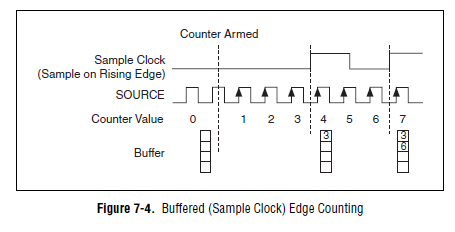
The counting begins with the relaxation of beginning of arm, which should be at the same time for both channels (with perhaps a shift of 1 tick, who would be 12.5 ns on the 6602). Count refers to increment the register of account of material at each tick of the input terminal (80 MHz base time in your case).
Sampling of the account register will take place at different times on each dependent channel when the photons are detected. So the temporal measures on each channel will be different, but if a photon should occur on each channel at the exact time you would get an identical timestamp on each channel for a sample. Sampling refers to the value of the register count in a buffer you can lock read later in the software.
This image (from theM-series user manual actually, but the 6602 should work the same way) watch your use case:
The time that the meter is armed is identical between the chains, so each counter at some point value would be equal. The time sample clock are not identical on each channel, so locked into the buffer values don't would not the same.
Using the same external signal to sample some registers simultaneously count shows that relaxation of arm early works (in other words, if you give the same sample clock counters, you get the same results). If the beginning of the arms did not work, you will see different results on each counter even with a same sample clock (the sample clock not to arm the meter). Out the relaxation of beginning of arm would confirm this point - arm tasks in the software (which is what happens with no beginning configured trigger arm) will give unpredictable delay between each task starts - you will see a difference between the channels, even with a sample clock shared.
Looks like the problem is that you could have if wait photons occur on the two separate channels at most close at the same time? You can try out photon detector to confirm whether or not there is a current backlog of the scope. Looks like it is - but this isn't what you're trying to measure? Expect photons to be detected by each channel exactly at the same time?
Best regards
-
Hello
I used a LabView program to collect data from SR400 via GPIB.
Now basically what I need is that we send the signal TTL SR400 and leave only the signals of photons in the synchronization time we want to get through.
That is why we want to use high (low) pressure to open the door and use the low tension to close, which means that we use the external signal to control the width of the door.
However, the width of the door is determined internally.
Could you please tell me how can I leave the signals of photons in the duration of synchronization we want to pass through?
Thank you!
Hi PbZhang,
It seems that the SR400 has a minimum of 5 ns door width and a maximum of 1s so door width as long as your desired door width is within this range, you should be fine.
The forum post below contains an example that VI attached which is a good start. I recommend to use it as a model
http://forums.NI.com/T5/Multifunction-DAQ/counting-edges-from-a-photon-counting-PMT/m-p/3005671
-
Only the 32 block RAMS and always showing error 3 used
Hello
I work on Photons counting upon arrival at DIO0. Short cut, there is a lot of data to come and I need to send it to the host as soon as possible. To do this, I used a FIFO extended target in a loop timed under unique bike and another target host FIFO taking this extended FIFO target data and send it to the host.
According to the analysis that I did, I need FIFO to 600 000 elements Boolean deep target. This should be possible since I use an FPGA virtex-5 wx30 FPGA which has 32 (36kbits) block of RAM. However, when I increase the number of items in this requested FIFO, compiling just can't say that code does not fit into the FPGA while it shows that only 3 of the 32 RAM block have been used.
I tried to search a lot on any restrictions on the FIFO, but I have not found.
Please help me here earlier.
I have attached the file VI and the sheet of newspaper of Xilinx compilation.
There are 6 FIFOs in this project:
The target host DMA (items I32, 1023)
Target to host DMA (Boolean elements, 2000)
Target to host DMA U32 (U32, 500)
Range of target DMA write (I32, 16000)
County of DMA scope target (Boolean elements, 108000)
DMA County U32 brought target (U32, 500)There is a bug in the compiler to Xilinx that not all types of block instantiated Rams are reported.
I did a similar discovery before. http://forums.NI.com/T5/LabVIEW/FPGA-block-RAM-FIFO-resource-usage/m-p/2978897/highlight/true#M85572...
Therefore, simply ignore the statistics of the compilation, they are wrong.
Block of RAM is not addressable as 36 k x 1 bit, it has 36 bit width or width 72 bits. This means that 1-bit, 2 bits, all the way to the top 36-bit all fill a cell block of RAM.
Therefore, your consumption will be 600 k x 36 bit which gives much more than what you're supposed to be bit 1 x 60000 storage trequirement.
1x600k is part of the block of 32x36k RAM (600 KB required, 1 MB free space)
but the reality is that
36x600k does not fit in the block of 32x36k Ram (21 MB required, 1 MB of free space).
If you can, try little racing Booleans in one FXP 36 bits before writing in the block of RAM will improve you things.
Maybe you are looking for
-
I have a "Macintosh HD". -What Mac has SSD (Solid State Drive)?
I have a 'Macintosh HD' end 2013. SSD vs HDD: http://ocz.com/consumer/ssd-guide/ssd-vs-hdd -What Mac is equipped with an SSD (Solid State Drive)? Jona li
-
windows server 2012 essentials disk partitions
I am to evaluate Windows Server 2012 Essentials for customers to small businesses. I use the trial version for testing purposes. My test server is a motherboard Intel S2600CP4, Intel P4000 chassis, E5-2630 CPU Xeon, Intel RS2BL080 RAID controller wit
-
I bought a Microsoft wireless router today, but it did not come with a cd. What should I do?
I bought at the flea market, so obviously did not expect, but when I went on the site, looking for a way to get a CD, nothing came. Anyone know how I could do to get one?
-
Hello I have a pavillion dv5 1058eo equipped of a corrupted Bios. Screen i black and codes led 2 flashes. This means that I have to replace the Bios. I tried with a USB pen with the latest bios drivers. I turned off the computer, the distasteful bat
-
How can I cut & paste in the address bar?
How to cut & paste? It's been too long, can not think! Help!