Detection of pulse NI 6259 photon counter min
Hello
I have a PCI 6259 DAQ card which I use as a counter. Is there a limit to the minimum pulse width it can count all operating as a counter? My meter of photons gives the TTL pulses with widths of 50ns which I think is less than what the meter may read unless I'm mistaken. I use 100 kHz as the clock source internal clock. Is there anyway to get the counter to pick up these small impulses?
The NI PCI 6120 DAQ card would be a better choice for this kind of measure? I should be able to get my hands on a bit of time.
Thanks for your time,
Select this option.
Well I just learn something new, I didn't realize earlier that the time base of 100 kHz could serve directly as a sample clock for the tasks of counter as described here.
The task of the meter must be able to count incoming edges at rates well in a few tens of MHz. If you stop the recording of managers when your fn Generator hits 1.5 MHz, I bet it's because the impulses become too round or too low in amplitude to be recognized as transitions TTL.
Try to insert a property node DAQmx channel between the creation of the task and start. Select the property "Counter Input-> edges of the County-> input terminal". Make a writable property and create a constant connection. Right-click the constant, select "Browse...". "and choose the 20 MHz or 80 MHz time base. Run it and check that you get always 200 or 800 counts per interval.
If using the internal time base works as expected, you will need to put emphasis on the integrity of the pulse of your fn generator and your real instrument.
-Kevin P
Tags: NI Hardware
Similar Questions
-
Salvation;
Here is the solution for your problem.
The cause is that "Gen dig Pulse Train-Finite" uses Ctr0 both Ctr1.
Please refer to:
"When you do a finite pulse train generation, a counter generates pulse train, and the other counter generates an impulse that acts as a barrier to the first counter. If you change the pulse train to generate continuously or
only generate a pulse, you can run two tasks of meter at the same time without error. »
http://digital.NI.com/public.nsf/allkb/04BEDD9E9E91ED3486256D180048116D
I used Ctr0 and Ctr2, jumping Ctr1 as it is reserved by "" Gen dig Pulse Train-Finite ". I works very well.
Kizito.
-
Photon counting using Photon unique cash Module and PCI-6602
Hi all
I am currently working on program couting of photons using a single (Excelitas) and PCI-6602 photon counting module connected to the BNC-2121.
I took a glance at other positions, but I still couldn't solve my problem (or, again, I'm not sure if yes or no, the problem is the specification of the material).
In the program, I'm generates a trigger to 1 MHz pulse using a trigger in a separate loop.
Other than that, I have loops of the producer-consumer model to get data and do a simple subtraction to calculate the number of photons in 1 microsecond.
According to the values connected to 'Input.BufSize' of buffer DAQmx and "Samples per channel" DAQmx calendar, I could change the loop number that the program has done its job correctly.
With the values, the program acquires photon 1 MHz with signls for 139 times.
After that, the program stops and the loopback number increases very quickly.
When I forcifully took stop the program, while the loop number increases very quickly, the program appears "error-200141".»
The error that says "data has been replaced before it can be read by the system." Mechanism of data transfer is interrupted, try to use DMA or USB in bulk. Otherwise, divide the input signal before taking the action. "even if the meter explicitly works in DMA mode by using the sample clock.
I wonder there is nothing that can solve my problem or even the only solution will buy a better Board of counters/timers.
Thank you all for reading this.
I will be very happy with any index

Kind regards
Myeongsu
Yes, the same thing happens on my system.
It does not happen with PCIe-6612.
I found more strange things:
When I start to reduce the frequency at a time given (800kHz) can fill the buffer, it will not start since the beginning of the buffer. He can go to the beginning of the buffer only at 100 kHz for my PC.
Options to fix:
(1) PCIe-6612. Seems to work. I tried streaming at 10 MHz, 5 min - fine.
(2) reduce the frequency of the pulse. If your laser supports 100 kHz, you're fine.
(3) put in place additional synchronous counter at 100 kHz. Basically, it's material average number of photons by 10 pulses.
(4) read 2 adjacent pulses each 1/50 kHz - then your data transfer will be 100 kHz and you will get the number of photons of this impulse of the 20 - th.
Programming issues:
(1) remove the display of the received picture, make only the processing of data and show results if you really need it.
(2) clock.vi sample sets the buffer size, if you specify the size of the buffer, do this after this vi.
(3) I deleted unnecessary "loop generation." He is running on the hardware and stops when you stop it - after reading the loop ends.
-
Helps the acquisition of photon counter data using LabView 12
Hey all,.
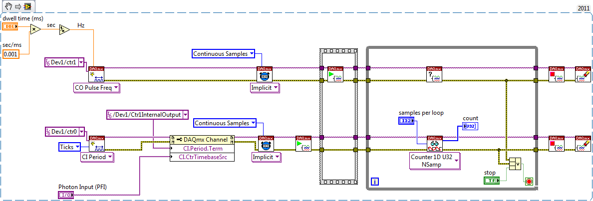
Student graduate Chemistry here new to LabView and are looking for some help moving in the right direction. I'm looking for help with connecting my meter to 12 LabView for data acquisition of trace-fluorescence photon PerkinElmer SPCM-AQR-14 (now owned by Excelitas Technologies). I just want to be able to acquire number of photon counts vs. time. Currently, I installed a PCI-6601 and use a BNC-2121 to connect the BNC of the sensor output. The detector has a pulse output digital TTL with 30 ns pulse width, and by contacting technical support on this issue, I was told that this pulse width was too short to always detected by the 6601, but can still go ahead and give it a try. Basically, if everyone is familiar with how to start with this configuration, ANY help would be greatly appreciated. As I said I'm all new to LabView and am currently spend all my spare time reading manuals and help files.
Please let me know if you need any kind of information to make me understand what I'm doing.
I would say something like this:
A measurement period the registry account out of the entrance of the samples as well as gives the meter. You will basically measure the 'period' of your sample clock fixed regarding ticks of the external photon signal.
According to the downtime, you may need to re-read several samples per loop so that the software can keep up with the incoming data. Also, the first sample is not useful because it represents the County between the software from the task of entry of the meter and the first clock signal - you should disregard/erase the first sample (or if you want you can set up a trigger to begin arms).
To do the same thing by using an edge County task would require using both the sample clock AND a counter reset signal - this not is not supported on 6601/6602 (even if it would be possible to set it up that way on a device of STC - 3 as a series of X).
Best regards
-
2D raster scan photon counting optimization
I wrote a VI for a scan 2D raster and pulse TTL of a photon counter to each pixel.
It seems to work very well and is to serve its purpose for now. However, there is something I want to improve
Currently, I have 2 loops, following the breast of one for each of the axes (x and y) for analysis. Then in the inner loop, I count the pulses. Now the problem I face is that I did not understand how to start the counter from 0 to each iteration. Instead, I do turn the meter twice in a for loop and the output of the difference between these two iterations using shift registers.
I want to do is not have to count it twice for each iteration. I tried the task start and stop vi, but they seem to be doing nothing.
The other thing that would be nice is to avoid loops. I heard that it is "expensive" to use loops and cause some general time in the program. I really don't think it bothers me at this point, but I think that if I do the scan rates more quickly then it might. I am currently scanning > 100ms per pixel.
(And also, for the record, my wavefrom raster is slightly different in that in is a 'triangle' instead of. saw-tooth that it goes to the end of the fast axis, then begins the following line at the end rather than the beginning to avoid sudden jerks in my gear.)
I enclose my VI. Thank you
Aditi
I can't help with your meter problems.
The loops have some overhead. It is the order of a few nanoseconds. Then the loops are probably a little slower than for the lines because of the additional test. Compared to your DAQ timing the time loop is totally negligible. Look at the below test program.
As you know (or can calculate) the number of steps, for loops is probably the best choice. I think that the conditional for the loop is available in LV 2011.
You probably need to move channels AO create screws and clear Associates screws task outside of the loop. Connect the wires to the task via the shift register ID so that the value will be passed in the event where someone enters the start and end values that lead to zero iterations of the loop.
Usually to speed things up you want to (indicators) out of the loop when it can be done without harming the feature all the calculations and display. For example, the division by two can be moved to the outer loop; the entries do not change in the inner loop. If you do not need to see every update immediately, reducing the number of writes to the curve of intensity amy speed up things a bit.
Avoid the right of left child and behind other objects. These have no effect on the execution of the programme, but they make it much more difficult to understand what is going on and the problems of fine. I have attached a version purified to the top of your program.
Lynn
-
Photon counting using the FPGA of the series R. problem generation TTL signals
Greetings,
I try to use the R series FPGA to read and count the pulses TTL of a discriminator (count of photons of the Hamamatsu C9744 unit) connected to a PMT (Hamamatsu-H7422P-40). The release of PMT looks fine (signal.png H7422P-40) but the discriminator wasn't able to generate corresponding TTL 5V pulse. There was some scattered and random spikes, but nothing significant. Instead, the only stable the PMT signal is a single + 5V pulse no matter how, I adjusted the PMT (C9744 output.png) control voltage. The PMT and the discriminator is connected by an ordinary BNC cable 50 ohms.
I am really confused because it was supposed to be a really simple installation. Anyone have a similar question or have similar Instrumentation (but no problem) configuration? Comments/suggestions are greatly appreciated.
Thank you very much in advance!
Hi Kelli,
Thanks for your help. Sorry it took so long to get back to you.
I actually found the question. The discrimination of the Hamamatsu unit level is set too high that all signals got filtered. After adjustment of the threshold of manuallyt, I was able to get the camera TTL pulses. And 7842R worked correctly for count impulses. Everything works fine now. Thanks again for the input.
-
Analog pulse of a photon multiplier tube
Hello
I am trying to establish if it is possible to count random negative analog impulses of a tube of multiplier of photon (PMT) with multifunction data acquisition OR or boards of counters/timers?
First of all, the properties of the PMT output are as follows (single photon response):
- 1.5 ns FWHM
- -50 mV to 400mv (random because of the amplification process in the PMT)
- Up to 5 million pulses per second (higher cause the overload sensor) who arrive at random times.
I would like to do is make the counting of simple events or events buffered count.
All counters seem to only be able to count digital TTL pulses. In this case, I have some electronics in mind which will convert the pulse the pulse of positive 5V CMOS logic (which, according to this site, is suitable for counter inputs) external signal conditioning. It also contains a dicriminator circuit to ignore the pulse below a threshold. With this signal, I intend to send to a meter entry NI USB Multifunction DAQ BNC for counting of events event / buffered.
However, in the hope to reduce the cost of my system, I was hoping it could be a way to define an analog trigger to create a pulse TTL of one of the of cards OR, therefore quite dodge the need for external signal conditioning?
Any help would be welcome.
Kind regards
Sean
You may need to strech the pulse to meet the minimum of the input of the meter.
I know you want to do without extra signal conditioning... However, we are building a signalconditioner to our task with a comparator MAX961ESA provided... 5V-driven layout is in the technical sheet

As a simple pulse strecher, I would try a simple low-pass RC before the entry comparer.
-
BIOS has detected a problem with cooling on hp Mini 210-1004sa fan
I tried to boot my system and received a message that the BIOS has detected a problem with cooling fan and if the system wouldn't start. Please, what is the best way to solve this problem.
-
Why my laptop detects only my neighbors wifi and not mine when it starts?
I have a laptop Dell Inspiron N5050 and in recent months he has struggled to detect and connect to my wifi, but it can detect surrounding wifi. I had to wait five minutes before he actually found my wifi, but then it does not connect to it for another 2 minutes because of "a problem with the access point. Then after that it connects to the wifi and works very well. Sometimes it will detect and connect to my wifi after the laptop is turned on, but it takes 5 minutes for the laptop to actually connect to the wifi. I need a permanent solution to this problem. I uninstalled and reinstalled my network card. I unplug and plug the router. I went to power management and unchecked "allow this computer to turn off device to save power." I changed my power supply with high performance options. I disabled my anti virus software. My wireless driver is updated. After doing all these things, my laptop still has a problem. The router works fine. My iphone, kindle and windows 8.1 Dell laptop my brother can connect to it. What should I do?
Hello
Thanks for posting your question on the Microsoft community.
I would like to know some information about the problem so that we can help you better.
You made any hardware or software changes on your computer before the show?
Thank you for details on the question and your efforts to resolve.
This problem can occur either because of corrupt network drivers or incorrect network settings.
I would suggest trying the following methods and check if it helps.
Method 1:
Run the network troubleshooting and check.
Reference:
Using the troubleshooter from network in Windows 7
http://Windows.Microsoft.com/en-us/Windows7/using-the-network-troubleshooter-in-Windows-7If this does not help, use method 2.
Method 2:
Reset TCP/IP and check the issue.
Refer to this article:
How to reset TCP/IP using the NetShell utility
https://support.Microsoft.com/en-us/KB/299357I hope this information helps.
Please let us know if you need more help.
Thank you
-
Detection of the Ipad vs. Ipad mini
Dear developers, through as3 code, I'm doing the difference between ipad and ipad mini. I would like to expand a bit the buttons on the mini, as when he shrunk down, they are just a little too small on the mini.
So I use this code
var resX:int = Capabilities.screenResolutionX;
var resY:int = Capabilities.screenResolutionY;
var tabdpi:int = Capabilities.screenDPI;and publish the ad hoc directly on the ipad mini. I use flash pro cs6.
resX and resY are correct, but screenDPI returned 132 instead of 163 (from the App on the mini). I read on another website that there is no way to tell the two apart devices, and it is the Apple of the way he wants. Someone at - he found a solution to this problem?
I could enlarge the buttons for the Ipad and then they would be sufficiently sized for the mini, but this solution seems inelegant.
Thank you
Justin
Technically possible, but somewhat fragile and subject to future breakage if you don't tell on top of new versions of material...
Adobe currently includes the hardware chain within the chain of Capabilities.os iOS device.
It is a string of internal material reported by iOS,
You can find classes and code that list these, as
https://github.com/mikezang/UIDevice-hardware
So currently you can distinguish a mini iPad iPad 2 by searching Capabilities.os for:
iPad2, 5
iPad2, 6
iPad2, 7
If new versions of iPad mini are released, but you will need to update your code.
As you mention, Apple would deter to distinguish the difference in all circumstances might well.
-
Rate for the low number of County Digital events
Hello
I'm trying to use the example of digital counting examples DAQmx Events.vi to count the pulses of a photon counter. As long as the light level is high enough, it works very well. But, when the light level is below a threshold, no count is read. I checked that's not because of the photon counter by testing with an independent instrument.
It seems like it might have something to do with the rate at which counted events are unloaded (PCIe-6321) hardware in the computer, that is, there is a minimum threshold of count indictment before such a transfer of data occurs. I'm voting for the number of levels of every 100ms.
Any help would be appreciated.
Thank you
Alex
-
FPGA to generate the counter and pulse train
Hello
I have some experience with Quartus, but new on the FPGA OR.
I have a PCI-7811R. I'm trying to use it to illuminate sequentially 144 LEDs repeatedly. The duration of each pulse is 480us.
Basically, I need to generate a pulse and generator of a counter to record the number of pulses and, according to this number, select which light is lit.
I designed a pulse generator train based on an example of using FPGAS and added a counter in it. You can see in the attached vi.
My question is,
When I put the I/O node inside loops call single cycle, it can generate the correct pulse. However, when I tried to use the local variable to transfer data from the SCTL and then plug it on another node of I/O, I can't detect the pulse signal when I measured this I/O.
Is there something wrong with my code when I try to transfer the data of the SCTL? Can I also use local variable to transfer the value of counter, because I will need it in the next part.
Thank you!
If you are referring to the wired local variable to DIO2 in your attached VI, the problem is very simple: it is outside a loop, then it executes only once. Put this local variable and the node of IO in a loop and I think you'll get something close to the impulse you expect (although if it is not in a loop of single cycle you will have exactly the same calendar).
-
How can I check if the counter entry is synchronized with the analog output?
Hello
I'm working on an application for counting photons. I use two channels of analog output on a PCI-6713 card to send a frame model to a set of XY scan mirrors. I then a photon count unit that emits a TTL signal when the photons are detected as a result of this raster analysis. I then use a surfboard USB-6211 to count the edges on this TTL signal.
I have problems that seem due to synchronization problems. I use the sample AO on the PCI-6713 card clock like the door of my meter on the map USB-6211. I use a trigger to start digital to analog output and a trigger of arms for the entrance to counter early. Is there a way to check that the analog output and counter entry of start of operations at the same time and are are synchronized? I basically want to monitor and compare the ao real sample of the PCI-6713 card clock door signal used by the jury of the USB-6211. I was able to export the sample AO clock and watch it on my oscilloscope, but not the signal from the door of the USB-6211.
Thanks for your help,
Brian
Update... It turns out that there is no problem of synchronization between my meter input and the analogue output. There was a difference of impedance when I connected my unit of counting photons to my USB-6211. This caused an error variable count rate. After accouting for this shift, the problem disappeared.
-
Average per minute and Reset counter
Hello
First of all this is the first time I programmed in labview. I have a device that allows to measure radioactivity (in the disintegrations per minute) and this device makes a sound every time it receives a signal from radioactivity, in labview, I did an application that uses the microphone of my laptop to detect this (high volume sounds) and counting the sounds, but my problem is that I need the counter to record values after each minute and only give me an average of these values) first minute 5 signals so in the Midland to be number 5 for example, the next minute I get 7 signals so the medium box will show me 6). Can someone help me please?
Hi Laurro,
-Use ElapsedTime to determine your minutes intervals.
-average: = (average_previous + new_value) /(i+1) with "i" being the loop iterator. You need a registry change to store the value for average_previous
Both are fundamental concepts of LabVIEW and you can learn with all these free beginner resources offered by OR on their website (Start here)!
-
Problem with the PXI-6534 elimination change detection task
I ran into the following problem. I use a PXI-6534 and PXI-6602 with vb.net for detection with a timestamp of changes. My code works fine and I get data exactly as I want, the problem comes when I try to call the task.dispose function.
When I call him has, she throws an exception with error-200088 code, task does not exist. But the task is still stopped and I can run my code again and everything works fine. If I do not call the task.dispose, I get an error when I try to run my code again. The material seems to have left in an unknown state, and I have to restart my computer to get it back. (the MAX NOR even reset the 6602, he says only that the Council does not exist).
Interesting also is the exception thrown does not seem to be caught by the Try Catch method. The code traverses the Try Catch without any problem (step by step in the code anyway), but with the exception, the message box appears, either immediately or when coming out of the subroutine.
Also, I use TestStand 4.2 to call these functions, if that makes a difference.
Any help would be greatly appreciated! Its very frustrating that everything works and I get my data perfectly, but I can't run the code without exception popping up, and I can't seem to catch the exception.
Here is the code I use:
    Public Sub StartChangeDetect_UUT1()
        If myCDrunningTaskA Is Nothing Then
            Try
                ' Create the task
                uut1ChangeDetectTask = New Task()

                '************************ Create the digital input virtual channel alias
                'Assign ports to digital virtual channel
                uut1ChangeDetectTask.DIChannels.CreateChannel("Dev1/port0:3", "ChangeDetectUUT1", ChannelLineGrouping.OneChannelForAllLines)
                'uut1ChangeDetectTask.DIChannels.All.DigitalFilterEnable = True
                'uut1ChangeDetectTask.DIChannels.All.DigitalFilterMinimumPulseWidth = 0.000001
                uut1ChangeDetectTask.DIChannels.All.InvertLines = True
                uut1ChangeDetectTask.DIChannels.All.DataTransferMechanism = DIDataTransferMechanism.Dma

                'Assign ports to monitor for change detection, both rising and falling edges
                Dim rising As String
                Dim falling As String

                rising = "Dev1/port0:3"
                falling = "Dev1/port0:3"
                uut1ChangeDetectTask.Timing.ConfigureChangeDetection(rising, falling, SampleQuantityMode.ContinuousSamples, 4000000)

                'export change detect event to PXI backplane so we can get timestamps from timer.
                uut1ChangeDetectTask.ExportSignals.ChangeDetectionEventOutputTerminal = "/Dev1/PXI_Trig0"
                uut1ChangeDetectTask.ExportSignals.ChangeDetectionEventPulsePolarity = ChangeDetectionEventPulsePolarity.ActiveHigh

                'uut1ChangeDetectTask.Stream.Timeout = 20000

                ' Verify the Task
                uut1ChangeDetectTask.Control(TaskAction.Verify)

                ' Set up the data table
                Initializeuut1DataTable()

                ' Create the readers for the DI and the CI
                uut1ChangeDetectReader = New DigitalSingleChannelReader(uut1ChangeDetectTask.Stream)

                uut1CDCallback = New AsyncCallback(AddressOf uut1ChangeDetectCallback)
                uut1ChangeDetectReader.SynchronizeCallbacks = False
                ' Set up our first callback

                uut1ChangeDetectReader.BeginReadMultiSamplePortUInt32(-1, uut1CDCallback, uut1ChangeDetectTask)
                myCDrunningTaskA = uut1ChangeDetectTask

                'Set up Timer for time stamp

                uut1TimeStampTask = New Task()
                '****************set up PXI-6602 timer to get buffered change events.  ie capture timer output on  the PXI_Trig0
                'we can then correlate this timer capture buffer to the change detect buffer to get the time stamps

                uut1TimeStampTask.CIChannels.CreatePeriodChannel("Dev5/ctr0", "TimeStamp1", 0.0000001, 0.02, CIPeriodStartingEdge.Rising _
                             , CIPeriodMeasurementMethod.LowFrequencyOneCounter, 4, 4, CIPeriodUnits.Seconds)
                uut1TimeStampTask.CIChannels.All.CounterTimebaseRate = 20000000.0

                'Use exported change detect from 6534 board to take counter sample
                uut1TimeStampTask.Timing.ConfigureImplicit(SampleQuantityMode.ContinuousSamples)
                uut1TimeStampTask.CIChannels.All.PeriodTerminal = "/Dev5/PXI_trig0"
                'uut1TimeStampTask.CIChannels.All.DuplicateCountPrevention = False
                uut1TimeStampTask.CIChannels.All.DataTransferMechanism = CIDataTransferMechanism.Dma

                ' Set timeout
                'uut1TimeStampTask.Stream.Timeout = 20000
                ' Verify the Task
                uut1TimeStampTask.Control(TaskAction.Verify)
                uut1TimeStampReader = New CounterReader(uut1TimeStampTask.Stream)
                uut1TSCallback = New AsyncCallback(AddressOf uut1TimeStampCallback)

                uut1TimeStampReader.SynchronizeCallbacks = False
                uut1TimeStampReader.BeginReadMultiSampleDouble(-1, uut1TSCallback, uut1TimeStampTask)
                myTSrunningTaskA = uut1TimeStampTask

            Catch exception As DaqException
                ' Display Errors
                MessageBox.Show(exception.Message)
                uut1StopChangeDetection("C:\PT3771\TestResults\")
            End Try
        End If
    End Sub

    Private Sub uut1ChangeDetectCallback(ByVal result As IAsyncResult)
        Try
            'If runningTask Is ar.AsyncState Then
            If myCDrunningTaskA Is uut1ChangeDetectTask Then
                ' Read the available data from the channels
                Dim data As UInt32() = uut1ChangeDetectReader.EndReadMultiSamplePortUInt32(result)

                Dim b As UInt32
                For Each b In data
                    ' in TestData waveform Y axix is data, x axis is time

                    uut1TestData.SetY(uut1ChangeDataIndex, b)
                    uut1ChangeDataIndex += 1

                Next b

                '' Set up a new callback
                uut1ChangeDetectReader.BeginReadMultiSamplePortUInt32(-1, uut1CDCallback, uut1ChangeDetectTask)
            End If
        Catch exception As DaqException
            ' Display Errors
            MessageBox.Show(exception.Message)
            uut1StopChangeDetection("C:\PT3771\TestResults\")
        End Try
    End Sub 'DigitalCallback

    Private Sub uut1TimeStampCallback(ByVal result As IAsyncResult)
        Try
            'If runningTask Is ar.AsyncState Then
            If myTSrunningTaskA Is uut1TimeStampTask Then
                ' Read the available data from the channels
                Dim data2 As Double() = uut1TimeStampReader.EndReadMultiSampleDouble(result)

                ' in TestData waveform Y axix is data, x axis is time
                Dim b As Double
                For Each b In data2
                    uut1TimeSum = uut1TimeSum + b
                    uut1TestData.SetX(uut1TimeStampIndex, uut1TimeSum)
                    uut1TimeStampIndex += 1
                Next b

                ' Set up a new callback
                uut1TimeStampReader.BeginReadMultiSampleDouble(-1, uut1TSCallback, uut1TimeStampReader)

            End If
        Catch exception As DaqException
            ' Display Errors
            MessageBox.Show(exception.Message)
            uut1StopChangeDetection("C:\PT3771\TestResults\")
        End Try
    End Sub 'CounterCallback

    Public Sub uut1StopChangeDetection(ByVal location As String)

        Try
            If Not (myTSrunningTaskA Is Nothing) Then
                uut1TimeStampTask.Dispose()
                myTSrunningTaskA = Nothing

            End If

            If Not (myCDrunningTaskA Is Nothing) Then
                uut1ChangeDetectTask.Dispose()
                myCDrunningTaskA = Nothing

            End If
        Catch ex As Exception
            MessageBox.Show(ex.Message)
        End Try

        uut1TestData.UpdatePointCount()
        uut1TestData.SaveToDisk("C:\PT3771\TestResults\uut1TestWaveFile.csv")
        uut1TestData.SaveToDiskBinary("C:\PT3771\TestResults\uut1TestWaveFile")
    End Sub 'StopTask
Joe,
Last updated. It seems that when the task.dispose is run, recalls seem to have called one last time. I took the call to the stopUUT1ChangeDetect in the two recalls (so eliminate it would not enforce a second time), and no exception was thrown.
Thanks for your help! Although if you'd still answer my question on the PXI-6534 Digital input filtering, I'd appreciate it.
Thanks again.
Thad
Maybe you are looking for
-
Constant light orange after firmware update
Hi all, Yesterday I message on there is a new firmware available for my Time Capsule (4th gen - 2 to). After installing this firmware, my Time Capsule never returned :-(After a minute or ten wondered what happened, because my signal is usually a minu
-
HP Envy 5540: blue light flashing
the printer that is connected directly to the laptop. Works very well. Now, all of a sudden, blue light flashing and will print still but at a snail's pace. What's wrong? Nothing has changed. Paper in the tray.
-
Windows will not start using fingerprints on Tecra M-series
When you start windows the fingerprint sensor to recognize and accept my fingerprints, but used to start Windows. When you start windows with password, appear on the display with text like "can't find the backup file. Try to remove the existing footp
-
How to tell the difference between default programs downloaded vs programs
How can I tell the difference between my default that is already installed on my computer and programs that were downloaded on my computer that I need to uninstall? I'm very nervous about to enter Control Panel and then try to decide what programs or
-
Please phone #999-910-0244 on my computer is slow?