Multichannel synchrobized meter output daqmx c#
Hello
I am facing the following problem:
I'm a piezocontroller operating to move a microscopic sample. The piezo allows me to scan XY of the sample areas. At each position analysis (to each "pixel"), I count photons for the image of the sample. Photon counting is a simple measure of pulsewidth and isn't important here.
What is important is that I have two types of piezo controllers in different configurations. A controller is digital and I can send the coordinates of the area to be scanned. The controller then allows me to define 4 output triggers to synchronize movements piezo with other operations such as opening and closing of shutters, photon counting after each pass of the step to a new position etc...
However, the second controller is an analog that only allows me to adjust the tension to move the scene. If I want to recreate the functionality of the digital controller I need to create four trigger lines myself.
So, my solution should look like this:
(a) I have a "clock" that ticks with a cycletime of 200 microseconds. At each tick of the clock tension in my piezo for X and Y motion are incremented. Master clock ticks are also triggers for the photon counting tasks at each position.
(b) the firing in four, used for various purposes, should behave as described in the two attached screenshots (pictures say more than 1 million words!). If for example it takes 1000 the master clock ticks to complete one scan line, then the line 1 trigger should for example be placed high the first 500 ticks, trigger line 2 should be high ticks the next 500 while line 3 trigger must be high all the time. This behavior must be repeated each line scan etc etc...
Is it possible to have this kind of coordination between the output of 4 meters to say, an edge of 6601?
Any help would be greatly appreciated!
Tags: NI Hardware
Similar Questions
-
Meter output that uses as AO start
Hello everyone,
I am currently using a PCI-6120 with a BNC-2120. In VI I have attached to this post, I have an analog output channel that generates a predefined signal stored in the memory of the Commission. Regeneration is activated so that the signal is emitted continuously.
The generation can be stopped and (re-) started at any time using a switch on the front panel.
Outside this AO channel, there is a counter. I would use this counter as the trigger to start for the AO, so that, when the switch on the front panel is set on WE, the AO task waits for the next rising edge of meter output to start the build.
Here's my problem.
When I run the VI, the first beginning of the AO is in fact triggered by the meter. The two generated signals are perfectly synchronized (AO and Ctr). BUT! After putting the switch to OFF and then back on, the signals are not synchronized more. AO task starts generating right samples after the start of the task, without waiting for the next rising edge of the output of the counter.
Could someone help me understand what is happening, please?
Why it works just after the execution of the VI, but not after using the switch on the front panel?
Thank you very much.
P.S.: when the switch is off, the AO job is not completely stopped. The OD begins to generate a constant value of 0 Volt. It's normal. I want to check the value generated by the Board at any time to avoid damage to the unit that I send the signal. So I force the generation 0 Volt, rather than simply stop the task.
LucG,
According to the S-series user's Guide, the time will be two impulses of your time base clock sample. So, it is expected.
The delay of the 2 tick must be for an internal sample clock. There should be no delay if you use an external sample clock.
You can check whether this delay appears when the sample clock is also used as the trigger for the start. I didn't realize this test.
If it doesn't, I think that your solution will be to buy another Board because I have already spent time yesterday to try something else like using the counter of seconds for example, but it really seems that there is no work around except buy a Board with a more recent technology.
Kind regards
-
Continuous output DAQmx and queue software
Hello
I'm coming out of a digital waveform on a map of data acquisition using the internal clock. Now, I also store the waveform for later processing by using the exact time at which the wave was written. So I would get a rear wave form that lets me know what state my digital output was at one point.
Y at - it an option to do this?
Or, as an alternative, could I somehow synchronize the beginning of the output waveform to the DAQ card with a timed loop? Because I know that the waveform that is written, this loop could return for example of this waveform with the good "t0" for each iteration.
The code runs on a target-RT.
Background: I'm controlling one instrument that has no indication of its current state, but I would like to save its current state on the entry of order.
After some research, I realized that there is a VI 'DAQmx create calendar Source' that returns a source calendar synchronized to the clock of the task DAQmx sampling. This source of synchronization can be used as a source of synchronization for a timed loop. There is here an example for this:
https://decibel.NI.com/content/docs/doc-25763
Unfortunately, I realized that my digital I/O hardware has no timing hardware capabilities so too, this does not work for me and I stick to a software solution that is timed.
-
With the help of LabVIEW 2009, I want to direct the output of ctr0 to several PFI. I looked at a lot of positions, but I'm still a little confused on how to route to multiple output.
It seems that there are three possibilities - DAQmx connect terminals DAQmx export Signal and DAQmx Channel property node.
Is it possible to get a pulse ctr0 to multiple output? If so, which of these options is the best? (I guess I'd several calls to the terminals or export Signal) Is there a limit to the number of exits can I drive with a signal ctr0?
Thank you.
Hi rls.
The best way to achieve this is to use the DAQmx VI of Signal to export. You can route the signal to several roads by selecting to go... rather than select a single line PFI, then CTRL + click on the roads to do. I was able to do this on a card PCI 6251 M Series multifunction with no problems.
Best,
-
to detect the meter output via the parallel port
I need to detect the meter count trigger, to perform an operation every time. I think passing the input signal pins (pins of status or control). The meter uses is omron H7EC.
I lowered the voltage of 24 V to 5 v with resistors.
But I can't get the entry via the parallel port.
All the stems of my status are still high.
What should I do, please help.
In the parallel reading write loop.VI, the splash screen is attached.
I suspect the entries on the parallel port pins have a resistance low pullup to 5V, so they tend to float high (logic 1).
Try to add a 4 700 Ohm resistor between pins of entry and mass of the parallel port, see if it then reads down pulldown (logic 0). If so, then keep the resistance in place and connect the signal of 5V that you want to monitor at the entrance.
-AK2DM
-
I keep me going in circles. I need to understand this because it seems so simple.
I have a digital waveform with a frequency of arbitrary clock. I want to send this waveform on a device USB-6259. I was able to do this with an analog signal and digital signal gives me problems.
For example, if I want to send a 7500Hz digital signal, I need to have the material, since the time of the application appears not to get up to about 1 kHz. But when I try to set up the schedule, it never seems to work. I'm going to make mistakes like that...
"External sample clock source must be specified for this application."
How can I configure things so this thing can clock the stuff at a particular rate. The analog part of the device doesn't seem to have a problem doing this, I do not understand why the digital side needs an external clock.
A modified version of one of the examples is attached.
VI attached
-
PXI-6133 Pulse frequency output and input with DAQmx
I am trying to set a pulse meter output frequency task and read this signal with a frequency counter input task input pulses. I use a 2 PXI-6133, each connected to a BNC-2090 case has. I want to output a square of a certain frequency with the task frequency meter pulse output and then read the frequency of this signal using a task of cost input frequency. I don't know how to property set up these tasks, or how to define which device to use for each heap. I don't know what terminals on the BNC-2090 is the counter of entry/sortient channels correspond to them because that is not displayed in the documentation of the PXI-6133 or documentation of BNC-2090.
Please see the attached VI for my attempt to put this in place. Currently, I get two errors:
(1) error-200452 took place at the property Node DAQmx channel meter Test - referred to as property is not supported by the device or is not applicable to the task.
2. the error-89136 at DAQmx Start Task - specified route cannot be met because the hardware does not support.
If I remove two channels of property DAQmx where I try to put the terminals for the counters, while the program is running, but then I know not what terminals on the BNC-2090 meters are connected to! This causes the DAQmx read for the cost in the tasks of frequency to timeout because it does not detect a signal.
I would really appreciate the help to properly configure these tasks and determine what terminals on the BNC-2090 case has the task of counter will work on.
I see a few problems in the code originally:
- For your CI task, you type is defined as a counter entry > frequency. But on the node property of DAQmx channel for this task, you modify the CI. Property of PulseWidth.Term. It should be CI. Freq.Term. set the entry regardless of the PFI line you do not want the input signal on. Tip: you don't have to type the name of the device in at all. Enter "PFI0", it's the same as "DevN/PFI0" since the unit has already been specified in the DAQmx Virtual Channel Create function. The name of the device, leaving aside will make your code more flexible where you decide later to change the name of the device.
- Maps of the S series, such as the 6133, do not have the same flexibility to change the output terminals of tasks of meter you might find with M or X series device. Page 83 of the S series manual watch what signals can be extracted to PFI lines - Ctr0Out is not one of these. Instead, Ctr0 out is, by default, pin 2. Cabling to a BNC-2090 6133 is certainly difficult to understand out (probably because the 2090 was designed to work with the materials of the E and M series), but if you compare the pinout of a PXI-6255 0 with the 6133 pinout connector, you will notice that they are essentially a match 1-1. Pin 2 is PFI12 on the 6255, so I assume the same for the 6133. All this to say, Ctr0Out always appears on the pin 2/PFI12 for the 6133 and you therefore cannot change the output terminal that your code is trying to do, having for result error-89136. Remove this node from the property altogether and the error should disappear.
-
How can I pause and resume the analog output using DAQmx?
I use a DAQ hardware to produce an analog waveform. I would like simply to break the output of the wave and then resume where it left off. I use DAQmx and LabVIEW 2011.
I've seen examples that use a digital or analog break trigger, but I would take a break in the software only. How can I do this?
-Joe
Hi Joe!
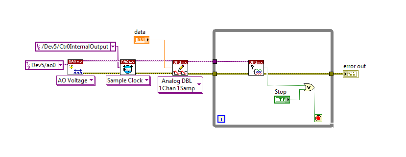
I spent some time thinking about it and I realized that you can technically use a fundamental mission of the analog output, as you previously wrote that runs continuously. However, the generated output samples are controlled by the sample clock pulses, and can be manipulated to fit our needs "suspension."
To do this, we will need another counter task that generates a pulse train (see our examples of shipping under material input and output > DAQmx > generating digital pulses > generate dig Pulse Train - Continuous.vi) that stops and starts the user to choose. This can be in another quite VI or controlled by software. We will use this as the task of our output sample clock.
Then, the task of the AO, wire a constant to the sample clock source and select ' DevX/CtrXInternalOutput"based on the counter that you specified in the task of counter. You will need to choose "I/o name of filtration" and check the box that says "include advanced terminals' and right-click of the constant. See picture attached as a reference. In this way, the task of the AO is constantly running, but it generates only actually all data when the meter running task.
Let me know if you have any questions!
Have a great day!
-
synchronize two exits of meter 6071E map
Well, that's usually how to synchronize two problem of counters.
I use the 6071E with DAQmx .NET 4.0. I set a task and attach to two channels with implicit synchronization and zero initial delay of meter output. When executing the program
I catch the first edge with a single trigger to scope. There is always a delay between the first edge of ctr0 and the first edge of 16.3 microsecs ctr1. Is it possible, not to mention that affecting the initial delay of ctr0 16.3 microsecs to make meter always start together? What is the source of the delay(software/hardware) and must always remain constant.
any help is welcome
The source of the delay is that while he is in the same tasks that the counters are always started sequentially by software. I'm surprised that the delay you see is constant.
If you want the counters to start together, you must configure a start trigger. As soon as you begin the tasks of meter in the software, issue the trigger to start to generate your pulse output. Relaxation of beginning must be a signal of material - for example, you can configure a digital outputs in software timing and the lead back to one of the PFI lines.
If you want to avoid any additional wiring, you could split the counters in two separate tasks. Trigger a counter with the internal performance of the other (start the task that will be triggered everything first). In doing so, instead of using an external trigger, I expect a delay between the order of 100 ns counters as the initial delay is at least 2 timebase tick.
Best regards
-
Specify the end point for the digital using an output circular buffer
When you use DAQmx and a NOR-DAQ for issuance of a digital signal using a circular buffer (buffer Renault). The program works and works, but when the 'DAQmx Stop Task.vi' function is called to end the task, he stops at the output buffering as soon as it is called and does not wait until the buffer pointer reaches the final value in the buffer. I would like that the program to wait until the buffer pointer is on the last value in the buffer, does anyone know how to specify this setting?
If you need to stop on exactly the last sample output you will need a way to trigger the stop in the material. The options available to you will depend on what hardware DAQ, you use, but here are some possibilities on the top of my head:
1. set up a digital output redeclenchables task finished (not all hardware supports). Set up a counter of output to issue a periodic trigger with the necessary synchronization signal such that the end result is a "continuous" digital output without interruption. When you stop your loop, stop the task of counter - digital output ends his generation but the trigger signal will be removed and so it will not continue after that.
2. If you have an unused extra digital output line, add it to your task. This line should exit 0 all except the last sample. Physically, this additional digital line in a wire line PFI and use it to trigger a meter output. Have the output counter generate a single pulse of some long-term (long enough to ensure that the software can respond prematurely). Use the output from the task of counter as a trigger of break for the task of digital output. Do not start the task of the meter until you leave your loop. Do not stop the task of digital output until you have detected in the software that the meter has been triggered.
If you need to stop on approximately the last sample output, you could query the TotalSamplesPerChannelGenerated property after leaving your loop and only stop the task once it reaches a multiple of the size of your circular buffer. This is no guarantee that it stops on the last sample (if you use a device on a bus with a latency higher as USB or Ethernet the non-determinisme would be worse).
Best regards
-
How do I output a digital signal to an analog signal
Hi all, I use a PCI 6221 with LabVIEW 2010 (no add-on) with the CB-68LPR connection block and I want to use an input signal analog of voltage of between 0 V and 5 V of an LDR to change the brightness of an LED, so I can maintain a stable lighting for a webcam capture feature level image and treatment system.
I can get the analog input voltage of the LDR (set up as a voltage divider circuit) using the DAQ assistant, via the channel of Ain 0 on the use of pins 68 (AI.0), 67 (AI GND) and 14 (+ 5 V) and write it in a graphic and digital display but I don't know how to write the value to a PIN that can be used for PWM I think assistance from pine 40 PFI 13 P2.5 and a digital (GND pin 13).
I looked at the example of code that was written to produce a PWM signal, but these programs don't signal to a device/circuit, they are just "nothing stuff" that the PWM signal to a graph.
Can someone help me or direct me to tutorials/code examples which are of real-world applications?
Hello
PWM can be done in DAQmx using a task of the meter output.
I think that example 'PWM-Counter Output.vi' goes quite a long way to do want you want I think. It is located in the LabVIEW examples of shipping.
I also found here:
http://zone.NI.com/DevZone/CDA/EPD/p/ID/1710
This could be useful a read thus:
http://zone.NI.com/DevZone/CDA/tut/p/ID/2991
Let me know if it's of any help.
-
Features VI DAQmx differently in LabVIEW that it does in TestStand
I particularly have a VI that generates a square wave signal to control the movement of a motor. When I run the VI in LabVIEW, after a certain time, it stops (a timer is also included in VI). When this same VI is executed as an Action (or boundary Test or pass/fail Test) in TestStand, the continuous PWM signal generating indefinitely after the VI terminated and (if necessary) results were returned to TestStand. If I followed this VI with an another VI which generates a square wave and a 0% duty cycle, the motor stops, as expected. However, I cannot rehabilitate the TestStand sequence without resetting the cDAQ chassis - and even in this case, every other time only. LabVIEW reports an error-200474 (expired timeout) and TestStand reports an error-200088 (task invalid or non-existent) on other tracks.
My questions are: why? and what can I do about it?
Hey Nessalc,
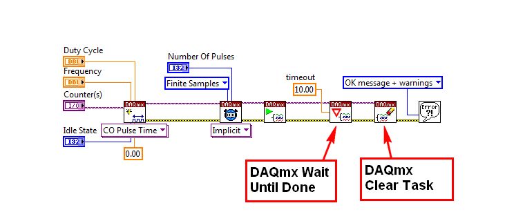
After watching your program, I think I understand why you don't see a signal on your oscilloscope. The test1 VI opens a reference to your task of meter output configures synchronization and then starts the generation time and again and more, without ever giving the working time to generate impulses form. Generally speaking, you would do this with a DAQmx's task made a Subvi wait until done (according to if it is a continuous or finite pulse train).
If you attempt to run a train of pulses for a period of time, see the example called Gen dig Pulse Train - Finite.vi, which can be found in the Finder for example of NOR (material input and output"DAQmx" Generating Digital pulses). Based on the value of the number of pulses and frequency controls, you can set up your device for a pulse train of output for a certain period of time.
I also noticed that you are not clearing your task at the end of the program. It is necessary to free up your resources before attempting to create another task for this resource.
The following image is a screenshot of the example program block diagram (Gen dig Pulse Train - Finite.vi). I have marked the key subVIs that I found missing in your application.
I hope this helps. Let me know if you have questions related to this issue.
-
DAQmx generating triggers TTL and triggered read it
I am running LabVIEW 2013 on a Windows 7 PC and I use a card PCI-6251 DAQ with a BNC-2110.
For my application, I need to generate triggers TTL (for example, with a frequency of 1 Hz). At the same time, I need to run data to HAVE which is triggered by the same TTL signal.
So far I managed to implement the TTL square signal properly with a spot of meter output - I can see the triggers on a scope. I also have a task of entry of HAVE and included a digital triggering. He works in part, and I have a few questions:
- The physical channel of triggering TTL is set to ctr0. This seems to be associated with the PFI12. I rather would specify the terminals directly in my program - is it possible? The ctr0 is not labeled directly on the BNC-2110.
- The task of IT is triggered by the PFI0. I connect a cable from PFI12 to PFI0. Is this really necessary? The task of the AI can be triggered internally for the same counter? My external hardware must be triggered with the same signal as the acquisition. So far, my solution seems to be the only way I can make it work.
- Digital triggering for the task to HAVE it is configured to 'rising edge' trigger. However, when I run the task to HAVE it continuously in a loop, it seems that it is triggered Alternatively edge bearish and bullish. I checked this by connecting the meter to exit on PFI12 directly to the input string for the task to HAVE it, and I observe that the periodic square wave changes sign. Why is this? It is a problem for my application - I need to be able to always trigger on this same Board.
Thank you very much for your help.
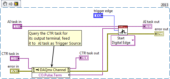
hmalissa:
You can query programmatically for the pulse of a task of the meter output terminal using a property DAQmx channel node. Here is an excerpt. Just save the image and drag the file into a LabVIEW block diagrom and turns it into code. You do not have to use this as a Subvi, controls & indicators are just there to identify the task who is who.
Bob: interesting experience. But to help future readers to draw the erroneous conclusion, I just would insist that a timed hardware task still * fact * produce much more repeatable calendar timed sample a software task programmed in a software loop. Example of Bob is not address the regularity of the individual sample interval, just by comparing the driver DAQmx or MS Windows timer is more sensitive (and repeatable) to marking the end of an interval of 1000 msec.
-Kevin P
-
DAQCard-6036E - meter channels synchronization
Hello
We have three devices we want to synchronize:
-' pressure' gives us an analog input
-"valve" needs a square via channel 0 counter wave pulse
-' cam trigger' needs a series of pulses of square via channel 1 meter wave
It works as long as it is the regulator OR the shutter of the camera is attached to the pressure. But when we are together, we get error 50103: resource is reserved. Does this mean I can't use two meter channels at the same time? At least that's what I guessed read other messages in this forum... Or sync not working correctly?
Someone has any idea how to solve this problem, or what alternatives are to use the channel to counter?Thank you for your help.
AndreaHello Andrea,
Thanks for the photos.
I did some research on the synchronization of the two outputs of the meter. Unfortunately the DAQCard-6036E does not support to synchronize the 2 exits of meter
Therefore, you got the error.
The reason is technology OR TIO, who only is not supported for cards E-Series.
Click on the following link:
Material Start Trigger counter for counter sync
http://digital.NI.com/public.nsf/allkb/9C657EE63C9D07A686256F6D0062AC66?OpenDocument
There would be an option if you have a cards M or X-Series with an ARM-Trigger
Synchronize two tasks of meter output using a task HAVE dummy
https://decibel.NI.com/content/docs/doc-11755
Kind regards
Rupert Donauer
-
How can I specify a delay generates a pulse meter?
Hi all
I have a question on the use of the meter to generate the pulse train. I did not how to program but I try the test panel in MAX and I see that it generates pulse train to certain rates and with a pulse duration. I think if it is possible to generate only a single pulse with given the duration of the impulse to sometimes after I start the job? I have a code to generate an analogue waveform, waveform of 35ms. I wonder if it is possible to synchronize the output of the analog waveform and counter such to 12.5ms after that the output waveform has started, I send this unique pulse from the meter port on. I have no idea how to do that, I think to use a delay but it is difficult to accurately control the time exactly 12.5ms.
Well, assuming DAQmx_Val_Low for the resting State, fires the meter will wait the initial delay and then generate a pulse at the time you request. Little time is not actually used in this example simple impulse.
From what you described, you must add a trigger to start your task of meter output (DAQmxCfgDigEdgeStartTrig) to you can set the meter to trigger off the beginning of analog output trigger. Set the initial delay on the counter for 12.5 ms. Start the task of counter in front of the task of the analog output. You should get your pulse 12.5 ms after you have started the task of the AO.
Best regards
Maybe you are looking for
-
How to stop the engine start sound
How to stop noise from startup on my iMac
-
my charger is broken on my PC toshiba m40x-103. for the charger part number is pa3432u-1ac3, but toshiba do not list it in the section of the electric accessories. Someone at - it ideas where I can get one where is there an alternative?
-
I want to design a user interface for the power supply laser. It has different setting to control and monitor, it has also the generation of pulse power monoring, measure of rate of flow water temprature sensor measurement and various locking systems
-
Need help to get my updates to run. Get the Code 80070002. Will not update. Windows Vista 64. Need detailed instructions for correct. Tried to not restore, no chance. I read some of the post on this problem. Still nothing works. Thank you
-
Sony VGN-FW31E of eye movement does not work.
My Sony VGN-FW31E of eye movement does not work, when I use the webcam it always shows video service bluetooth does not work. How can I get help from sony or other means? Thank you Evelyn