(3) multiple analog inputs (DAQ) Ai3 is copy Ai1 why?
Hi all
I've been a user of LabVIEW for about 4-5 years, but this is my first post on the forums. I wrote a code that will collect three entries, an acceleration (of the accelereometer) measured in volts, strength (from a counter force) also measured in volts, and a unique tension of a thin piezoelectric film. For simplicities sake you can just think of them as three well under the maximum 10V voltage inputs. Each tension is supplied with Ai1, Ai2 and Ai3 in my DAQmx measurement Board.
The purpose of this code is to study how a 3d printed energetic vibrations harvest table of coated piezoelectric beams performs under different conditions of excitement. (If we shake harder or softer beams at different frequencies, the amount of energy can us our table colelct)
However, I noticed that my piezoelectric measurement is often completely wrong. The measurement of acceleration data are for some reason above coppied and appear in my graphics rather than the correct data of the Piezoelectric sensor! I don't understand why this is happening. If I short circuit Ai1 and Ai2, Ai3 (which has the Piezoelectric sensor) work very well and give me the correct measure. But when I try to measure all three at the same time - it always gives me a wrong result.
I was wondering if someone could take a look at my VI to see if I'm possibly using code collection data incorrectly. Or is there another method to perform the same task that could isolate Ai1, 2 and 3 in a more clear and well-defined way. (but they still need to all get collected at the same time!)
Thank you for all the recommendations you have. My code is attached.
I have not watched your VI because the problem is almost certainly in the material. You probably have "ghosts." Your piezo sensor connected to Ai3 probably has an important source impedance while other sources have much lower impedance. Search the Forums for ghosting for more details.
The best solution is to provide a package of signals (essentially an amplifier with a low output impedance) between your piezo device and the acquisition of input data.
Another possibility, suggested by your comment about shorting Ai1 and Ai2 is to add one or two unused channels between the low impedance inputs and piezo entry. Short entries (in the same way you did Ai1 and Ai2). Read all channels. Throw the data for channels short-circuited. This is how it would look:
Short AI1 accelerometer, Force Ai2, short Ai3 Ai4, Ai5 piezo. Read the Ai1:5 channels. Discard data for Ai3 Ai4. While this may work for prototyping purposes, it may be not a good long term fix.
Lynn
Tags: NI Hardware
Similar Questions
-
read the multiple analog inputs at the same time
Hi all
I use USB-6001 and want to develop an application to multiple tasks in C++. I try to read several analog inputs at the same time, but got some errors. To put it simply, I copy one of the sample code to read in analog data in a channel, and then turn it into function. Then I call this function to thread with the names of different poles (for example Dev1/ai0, Dev1/ai1) and I come across this error:
"The specified source is reserved. The operation can not be specified such complete"code of State-50103
I have search the forums, this may be because I use the hardware timing in this function, and this material timing cannot be used simultaneously by multiple tasks. I may have to put all the lines, I want to read in a single task (such as Dev1 / ai0:1). This way I can read two lines at the same time. However, when I try this, I encounter another error:
Status code "buffer is too small to contain the data read" - 200299
So here is my question, what should I do if I don't want to read the multiple analog inputs at the same time? Is the thing that hard time cannot be used by several true task? If I have to read several lines to a single task, how to set the settings?
-
Issues of analog input DAQ-6008, voltage not zero to pin when you are offline
I use the 6008 NOR-DAQ to produce a series of tensions and then read a sense resistor using the analog input (CSR). I noticed that my analog input gives me 1.3 V, when I probe it (compared to the mass of the device), when it is completely disconnected. This changes the reading to give me a different measure of sense than expected resistance.
Why is my pin for analog input non-zero? Any help would be appreciated. Thank you!
The 1.3 V is expected. The USB-6008-and-6009 case have the strangest input of the world circuit. The input impedance is approximately 144000 ohms terminated in 1.4 V. check the document User Guide and specifications.
Lynn
-
How to measure multiple analog input at the same time.
I tried to do a VI that controls a motor with two buttons. If I press the buttons, the VI took the analog signal from the buttons and the engine is running. Each button covers the different direction - to the left and to the right.
I need to enter the two report in the VI at the same time, but I can't. If I run the VI, VI takes only a random signal. I want to know what are the problems and how to solve them. Please help me.
You must use a single task for both channels. See if that helps.

-
How to read and scale of multiple analog input channels
Hello
I'm reading the data of several types of sensors, with readings of 4-20mA. What I'm trying to do, is have a pressure transducer, a flow meter and a RTD sensor all connected on channels 1, 2 and 3 of my cDAQ using DAQmx. After channels are put on the scale, I need to see all the data in a chart of the wave with the scales on each side, identification of pressure, temperature and flow. Finally, I need to write that data to a text file. TDMS is fine, but for now, I'm working with a CSV file.
So far, I got my VI to read the data channel and the data on the scale correctly. I'm also writing to the file works properly. However, when I try to change the second channel, nothing happens or I get an error. Can someone help me on this? I have experience to come Monday to it so Im a little short of time. Ive fixed this Ive got so far (Ive got several versions of this VI trying to do this in various ways).
With respect to the accuracy of the readings for channel 0, Ive been using a deadweight Tester and a manometer calibrated to see readings. So far, these are correct, and I was able to calibrate other gauges with this interface.
Way easier and more foolproof that I found to do this is to set up several channels using an Express VI (DAQ assistant) and then made a right click on the object of block diagram and 'open the fron Panel '. Click OK to the warning and you will be pressented with an example of a multi-channel configuration.
As to the best way to get 90% it when learning DAQ configuration...
-
Synchronization of two inputs frequency meter with several analog inputs
Hi all
I'm relatively new to LabVIEW and I'm trying to collect data from multiple sources with calendar sync on the acquisition, but I can't understand. My problem is that I have two inputs frequency meter, an optical tachometer reading one pulse per revolution and a max flow meter machines with a 12000 k coefficient. I can't find a way to synchronize the calendar with my multiple analog inputs. I tried to first get the speedometer to synchronize with the analog inputs following the example linked here. (https://decibel.ni.com/content/docs/DOC-10785) So far every time I run it I get an error on the DAQmx read timeout or an error "several sample clock pulses have been detected" (see image). It seems if I slow the way to down to say 10 hz and make sampling rate ensure that the tachometer signal is more than 800-1000 rpm (13-17 Hz) before starting the VI then the program will run without error until the ROTATION speed is below this threshold, then the "sample Multiple clock pulses" error occurs. The code is attached below.
Does anyone know of a better way to synchronize the entries of frequency of the counter with analog inputs? I would like to have a VI that can display 0 RPM (and possibly 0 flow as well, but I think I need to understand the timing of a meter before I have add another, because it seems that I can't have two counters to the same task). Any help on this would be greatly appreciated.
LabVIEW version 13.0
Chassis cDAQ-9178 with NI 9401 for both counter inputs and NI 9205 for the analog inputs.
Thank you!
Richard
I know the error requires to restart the task at least (this particular error puts the material in a State that cannot be recovered from during execution of the task - I've been down this road before) but I'm surprised that you would have to delete and re-create the task altogether. And then I had to do this to workaround other questions in the past. It is awkward and should be considered a bug, if this is indeed the behavior.
Honestly, regardless of this bug, the way the material dealing with the situation of several sample clock edges makes measures of sampling frequency clocked essentially unusable for purposes of synchronization (in my opinion anyway) If you encounter a more slow than your sample clock rate. You are supposed to be "synchronization" of the measure, but it really no longer applies if you have to restart the task over and over again (if you must delete it or not).
Workarounds can get kind of creation (which isn't really a good thing). For example, you can configure a measure of implicit frequency to keep a buffer of frequencies and use a leader board task (source is the frequency signal, sample clock is the sample clock HAVE) to establish a correlation between the index of your buffer of frequency for singing HAVE sample clock.
Best regards
-
Several analog inputs seem to change any of the other (details DAQ: 2120 BNC and 6062E)
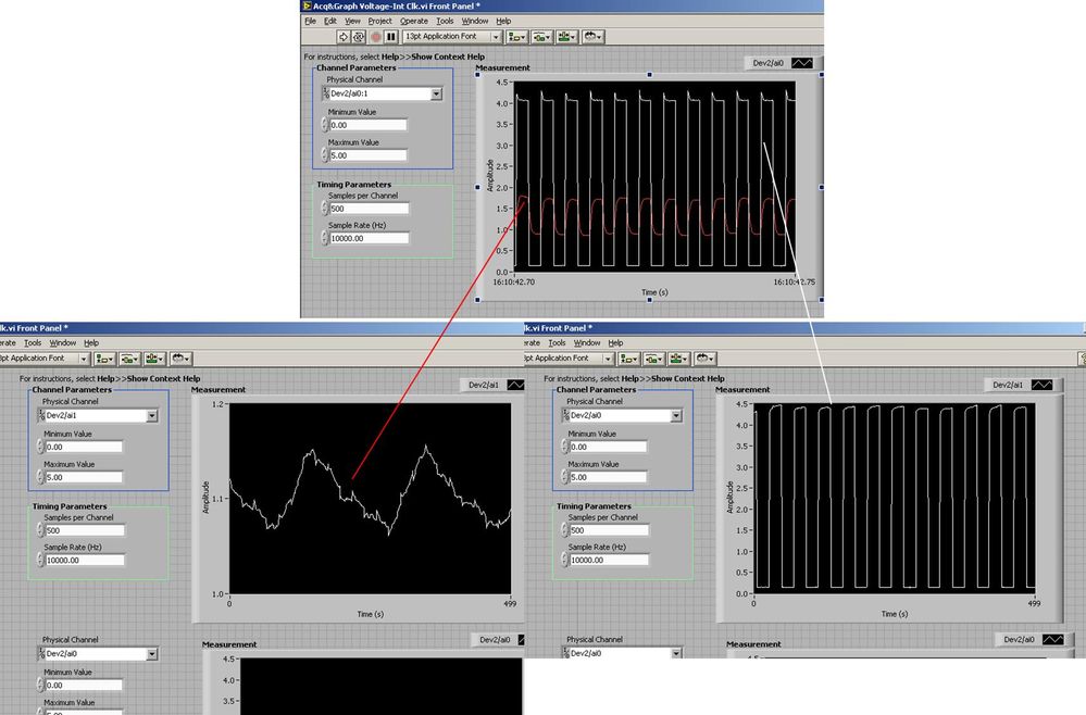
I use the BNC 2120 DAQ board connected to the data acquisition card 6062E to record two analog inputs. An entry is connected to ai0 and the other at ai1. Example vi: "Acq & graph int clk tension" has been used to measure the two entries with the value read NChan NSamp vi (channels being dev2 / ai0:1). The output is the top graph in the image. However, this seemed a bit strange to me that one of them should be modulating with a different frequency. When I record both entered individually (two in low pictures) they are indeed different since the entries shown in the top graph.

Why this would be the case, and how can I overcome this to measure the real signals?
Thank you!
The E series card takes the samples as soon as possible. Thus, for example,.
If you have 16 analog input channels but you only read of
channel 0 and 1, the map will show the channels 0 and 1 right
After and then wait 14 'ticks '. What's that little run-in
the origin of the afterglow.
I think you can get the card to wait a certain
number of ticks with a property node. I have attached a screenshot. You
can find the property node in the palette of functions >
Measurement of e/s > NOR-DAQmx > node Timing. Expand it
Property node so there's two entrances. The properties are in
Left click on the node and going more > converted >
Its properties delay units and sampling clock delay and delay that
you want.If the phase is important so the above is not the best
the option because it causes a delay in phase. So, if you need true simultaneous
sampling, then you will need different hardware. The S series is everything
simultaneous sampling.Or, rather than the Delay property and delay units, try the Rate property
find more > converted > rate.If this is not
work either, you can move the second signal source to, say, AI8 and
Connect everyone to the ground. Readings for these, but just do not take into account
the data. In this way the ADC will sag to the ground at the time where that can happen
the second string in the way so that you should not see this frequency
ghosting on the other channel. -
Analog input voltage assistant DAQ
Does anyone know why theres error when you use two assistant DAQ (in a while loop at the same time) for reading of the analog input voltage?
There is not a problem if you use a wizard to data acquisition for analog input voltage reading simple.
If you get an error, wouldn't it useful that you have told us what it was, we may be able to explain it?
I'm guessing that you have error-50103, and if you look in the forums for '50103' (leave out the negative sign), it will give you the answer for this question has only requested thousands of times before.
-
Using the DAQ USB-6009 meter and an analog input voltage at the same time.
Hello
Currently, I'm reading the two channels of voltage with the USB-6009. It happens that one of the channels is the output of a digital coder, and it would be much easier to use it directly to the PFIO entry that is defined as a counter. The problem I am facing right now, it's that I can't use the DAQ Assistant to use the analog voltage to a channel and the digital channel counter at the same time. Once I put the DAQ Assistant to read the input from analogue voltage, I won't be able to add analog inputs. And as I put the DAQ Assistant to use the PFIO as a counter, I can add more entries to read analog voltage is.
I wonder if it is possible to solve this problem using the lower level data blocks? Another solution would be to read two channels in analog input voltage and that the use of Matlab to process data resulting from it, since I was not able to do the counting to work simultaneously with the acquisition in Labview to impulses.
Hope you guys can help out me.
Thanks in advance.
Using a simple wizard of DAQ is incorrect. You need one to acquire analog inputs and one for the meter.
-
How to create different types of analog inputs without using the DAQ assistant?
Hi all
I would like to create multiple entries multiple analog channels of type... I mean I want to have the voltage of 5 and 2 channels of temperature...
However, I am not using the DAQ assistant. I use "create channel" vi.
Can anyone suggest me please how to do / I submit my VI for reference... I have 5 tensions, and 2 temperature characterized as showing these 2 two separate graphics...
-
Continually acquire analog input, internal clock, break, Multiple device
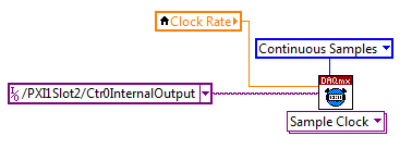
I have a PXI chassis with 6 cards SMU-6363. I want to acquire data on the channels of each SMU-6363 map continuous AI, using the internal clock for timing. I need to use a trigger to pause reading of a DI on one of the cards SMU-6363 for a break and to reactivate the acquisition. I came across this example: https://decibel.ni.com/content/docs/DOC-12256/ , but keep getting error-201019 DAQmx start task "trigger break is not supported in a task to more devices. To configure the start of break in a multi-device configuration, you must use no more than one device per task and route manually clock in demand signals. »
The problem is that the configuration of I is made during execution by the operator. Sometimes they want to acquire data on one HERE through all 6 cards SMU-6363, sometimes they want to acquire data on each channel of AI through all 6 cards SMU-6363. What makes the task definition until manually route clock signals between devices for each rather difficult task.
Is there a simpler way to solve this problem?
Set a task to output counter - something like this:
Next, configure your task of analog input to use the sample clock output of the meter:
Best regards
-
USB-6211: analog input signal affecting another of the same map AI
Hello
I use the DAQ-nor-6211 map and DAQmx features to read a hammer and a signal of the accelerometer and then use other LabView functions to make the FFT of these analog input signals. However, it seems that the analog inputs where the hammer and the accelerometer are connected generate a kind of noise or influence in other entries of this data that is not connected to any other sensor acquisition board.
I've had different experiences in order to check if the problem is with reading the card: put the accelerometer and hit the dog in another table where the DAQ card table was located (to avoid the vibrations on the map and a possible noise), ai1 entry was logged on the differential mode on the dog and the ai4 of entry is connected to the output (z axis) of the accelerometer. The other 2 ai2 and ai3, entries that can also be read by my LabView program, are open (i. e., any other sensor is connected to the card). When the structure where the accelerometer is located is struck by the hammer, the signal of ai2 ("x axis" seen in the first attached document) has a curve (on the time domain) which initialize almost at the same time that the hammer and the a3 of entry has a weak signal, but with the swing as well as the signal of ai4. The document "hammer ai1 + z_axis connected_ _x_axis disconnected ai2 + y_axis ai3 ai4" images that I captured the chart created in LabView. On these graphs, it is possible to check on the FFT the ai3 signal and ai4 has the same behavior (with different intensities), and enlarged figure of time domain image, we can see that the signal of ai2 increase almost at the same time of the signal of the hammer (ai1). The signal picked up by the sensors are probably creating a sort of noise on open entries ai2 and ai3.
Another experiment was conducted to check if the signal from a single entry that may affect the signal read from each other near the entrances: the DAQmx task Create channel had a physical channel has changed: ai3 entry has been modified by ai7 (maintain the same connection mode: differential), and the results are visible on the second attached document. In the graphs obtained in this experiment, it seems that the entrance of the hammer (ai1) affects the signal of input ai2 and ai7, which are not connected. And the ai4 signal does not seem to influence the other inputs, because he has a different curve on the graph of the FFT.
The same experiment was conducted using the CSR connection (change threads and create the DAQmx Channel Configuration), but the results were the same as those found using differential connection.
Finally, if the output of the accelerometer is connected on the ai2, the signal of the other open entries ai4 and ai7 seem to be affected by the signal of the accelerometer on ai2 (last document attached).
Could you tell me if the problem I encounter is caused by the DAQ card with this information that I gave to you? And if the answer is Yes, do you know if there is a way to avoid this noise create in one entry on the other hand, it please?
Thank you
Maybe Ghosting or crosstalk? Just an idea.
-
What is the minimum response of analog input, through DSP online, output analog time?
Hello experts!
I want to know if it is possible to get a very quick response latency (~ 1 ms) sound recording (analog input), through online registration (DSP online), the presentation of his (analog output) processing, by using the DAQmx programming codes. My system of NEITHER includes NOR SMU 8135, SMU 6358 DAQ Multifunction controller and SMU 5412 arbitrary signal generator. I also have access to the latest version of Labview (2015 Version) software.
My project is on auditory disturbances, which inovles record vocalizations, manipulating the recorded vocalziations and then present the manipulated vocalizations. My current idea of how to achieve this fact triggered output voltage after reading the input using DAQmx Read samples. DAQmx Read output is filtered online and then passed as input for the DAQmx writing for analog output. For purposes of illustration, examples of code are presented below. Note for simplisity, codes for the trigger part are not presented here. It's something to work in the future.
My question here is If the idea above should be reaching ~ 1ms delay? Or I have to rely on a totally different programming module, the FPGA? I am very new to Labview so as to NEITHER. After reading some documentation on FPGA, I realized that my current hardware is unable to do so because I do not have the FPGA signals processing equipment. Am I wrong?
Something might be important to mention, I'm tasting with network (approximately 16 microphones) microphones at very high sampling rate (250 kHz), which is technically very high speed. Natually, these records must be saved on hard drive. Here again, a single microphone is shown.
I have two concerns that my current approach could achieve my goal.
First, for the DAQmx Read function in step 2, I put the samples to be read as 1/10 of the sampling frequency. It's recommended by Labview and so necessary to avoid buffer overflow when a smaller number is used. However, my concern here associated with the latency of the answer is that it might already cause a delay of 100 ms response, i.e. the time to collect these samples before reading. Is this true?
Secondly, every interaction while the loop takes at least a few tens of milliseconds (~ 30 ms). He is originally a State 30 late?
Hey, I've never used or familiar with the hardware you have. So I can't help you there.
On the side of RT, again once I don't know about your hardware, but I used NOR myRIO 1900, where he has a personality of high specific speed for the RT where I can acquire the kHz Audio @44 and process data. Based image processing is ultimately do the treatment on a wide range of audio data you have gathered through high sampling frequency and number number of samples as permitted by latency, please check this .
I lost about 2 weeks to understand host-side does not work and another 2 weeks to understand the even side of RT does not work for online processing (real time). Then, finally now I'm working on FPGA, where the sampling rate is 250 kHz (of course shared by multiple channels).
The complex thing with FPGA is coding, please check if the filter you want is given below as labview automatically generates some codes of some filters.
Most of them will work in 1 SCTL IE if your target has 40 MHz clock algorithm will run in 25 ns. That's what I was looking for, I hope you

See you soon... !
-
Toggle the analog inputs and tasks of output on the same card in LabView
Hello
I'm relatively new to LabView and am trying to find the best way to switch between reading and writing tasks on my PCI-6024E. It seems this would be a common thing to do, but I found no good documentation or any relatable example program. Basically, I would like to be able to monitor certain analog inputs and then write that some outputs if an entry is in accordance with certain specific conditions (say > 4 Volts voltage). It is my understanding that you can only signal (input and output) types associated within a single task in DAQmx. I also understand that you cannot have multiple tasks running at the same time on the same material/map, otherwise you get a: 50103 error 'The specified resource is reserved. Calendar is not really all that matters to me, but quite synchronous and effective would be nice.
I have attached a sample program that shows more or less what I'm trying to do. I want to follow several analog input lines (AI0 AI1, AI2 and AI3 and) effectively at the same time. If certain conditions are met, AI3 > 4 Volts, then write 5 Volts for analog AO0 and AO1 outings. I also want to maintain output at 5 Volts up to AI3 falls below 4 Volts. Is there a better way to pass the task to read and write than what I've done here? In a sense, all I really do is toggle of a state machine if the required conditions are met and if start/stop tasks of reading/writing necessary.
One last question, is there a way to display the four channels in the waveform graph using the 1 d NChan 1Samp mode so I can have a time chart and indicators?
P.S. I'm under LabView 2011 on Windows 7. Your ideas and suggestions are appreciated.
Thank you
KJ
I also understand that you cannot have multiple tasks running at the same time on the same material/map, otherwise you get a: 50103 error 'The specified resource is reserved.
This is incorrect. You can't have two tasks of the same type running on a single card. You can have an analog input and analog output task running simultaneously on the same hardware.
You are right that each task can have only one type of task (entry or exit). Discover DAQmx examples in the example Finder to get examples of synchronized input and output.
PRO TIP: In the Finder of the example, go to the drop-down list in the lower left corner. Pull down and select Add Hardware. In the pop-up window, add your PCI-6024E to the right pane. Click OK in this window. Then in the main window of Finder example select your hardware from the drop-down list and check the filter results by the hardware. The example Finder then only you will show examples that are out-of-the-box compatible with your hardware. I am sure you can find something to fit your needs here.
-
Problem with analog inputs on sbrio 9627
Hey guys!
I have a problem in my Single Board RIO 9627.
I use 4 differential analog inputs (AI0, AI1, AI2 and AI3).
What happens is that when I place a sensor or even a button on one of the entries and nothing on the other inputs, it affects all other inputs, increase in the level of each input voltage.
Can someone tell me how to solve this problem in the hardware or software?Thank you!
Multiplexed inputs must have a low impedance! If you have pictures of ghosts.
Attach entries open to GND (or do not read
 )
)If you want to read switches or buttons use a pull upwards or downwards the resistance.


Maybe you are looking for
-
chip Z50-70 problem reboot / restart issue and 8 GB ram
Salvation;I have lenovo z50-70 notebook with Intel i7, 8GH RAM and 250 GB of kingston SSDThe bios of the laptop is v.29I installed win 7 PRO 64-bit operating system.The system has worked well for about 2 weeks. After this time I noticed the strange q
-
Fixed problem NetFlex siverlite
How to fix
-
Hi all Here is my problem, I have a great app must locate a Blackberry all the time, when possible. I made one to or 4.5 and knit perfectly until the OS6.0. So I did another in the OS6.0 with new features. The problem is at the same time (after 12 ho
-
Library Media Player does not always update or the latest.
My Windows Media Player library do not update or the latest that arrived it convert mov to MP4 using QuickTime Player Pro. I even restart the computer, and still, he isn't here. The file mp4 in question is 107 MB 50:54 minutes. I am running Window
-
NAV: Phone step void nav buttons jump the closure of hamburger nav?
I had a problem with the nav for a good few weeks, finally discovered that its to do with opening and closing, see the screencast: Nav Muse test 2016 - QuickCast. Do. Publish. Share. 3 minute screencastWhy the subnav does not align properly when clos