33522 A function / arbitrary generator of signals, 30 MHz
Hello!
I got 33522A function / arbitrary generator, 30 MHz. I want to make two squares of 30 kHz signal, one on each channel. Trick is that the waveform must be a reflection. I have a problem is, I was wondering if these signals is sysncronise if I drive it through LabView.
I played around with one of them in the past, and these signals must be synchronized without any special order.
This can be done on the front of the unit or through LabVIEW. The easiest way to set this is that same string except for the amplitude parameters, make the amplitude of a negative output from the other output.
One thing to know...
Although that synchronized, sometimes there is a difference in light phase between the two signals, you may need to adjust the phase of one of the signals to match the other. This is best done with an oscilloscope.
See you soon,.
McDuff
Tags: NI Software
Similar Questions
-
I can't generate multiple signals with different phases.
Hello community!
I created a simple signal generator versatile (see Signal "Generator.vi"). When I try to put two of these generators in the same VI ("testbed non working.vi"), I'm not able to independently change the phase of the two signals. Only one of the two phase buttons actually modifies the two signals, while it has no effect.
However if I copy and paste the exact schema even twice in the same VI, rather then import VI Builder, everything works fine ("Test Bench working.vi").
It seems to me that the two generators are sharing anything other than the phase variable. I'm new to LabView and I can't understand what is happening and how to fix it. Can you please help me understand?
Thank you very much
Hello
This is because multiple instances of the basic vi function generator will work regardless - they share information.
To fix this one true constant wire to signal to reset the basic vi function generator enter your generator of signals vi.
Best regards
Florian
-
How to generate analog signals?
Hi all
I'm trying to generate analog signals to simulate the position of the valve. I also want to simulate the position of the valve 0 - 5V (analog signal). I've implemented the numeric position of the valve by using the toggle switches, but I want to implement analog signals.
You can help.
Thank you
You can just use a random number generator.
Since you have no generator hardware signals of NOR, I'm not sure why you are posting to this Board. Generic questions of LabVIEW. Post to this Board.
-
Connection diagram missing in DAQ Assistant generate the signalling block
This is my first post so please excuse the quality of my description.
When I double click on the block of data acquisition - Assistant, there is no tab connection diagram I can access to see how things are wired to the top. I have a NI USB-6211 connected by USB and it is used to control many different sensors and a power supply. Currently, he works for everything and is hard wired correctly, but only blocks DAQ Assistant has a connection diagram available, the other are not. One who has a connection diagram is used to measure a voltage. Others who do not are used to generate a signal. I would really like to be able to see patterns of connection for each block.
-Any help would be appreciated
-Thank you
You can always do like those who never use the DAQ Assistant and read the manual. Right click on the device in MAX and selecting "stitching of the device" works too.
-
Hello
We need power RF amplifier with a function generator to create plasma in an ion source. The signal pulse duration must be 1ms long, repeated twice per second.
Today, we work in the following way: we spend the RF with f0 (aprox 1,995 MHz) frequency. After 20, we send a trigger signal passing frequency f1 (aprox 2.005 MHz). We keep this frequency for the rest of the pulse. However, the plasma that we generate is not 'constant' or stable during the whole impulse. If we smoothly change the frequency during the pulse we could improve.
We would like to do: use the frequency sweep: rather than use this frequency hopping, we would like to move smoothly f0 f1 (frequency scanning). Then F1 to f2.
As we have a PXI for data analysis, we believe using the arbitrary function generator of NOR: 5406 of NEITHER allowing the frequency sweep. However, in the book loads, it is not very clear, and I have a few questions:
-We can create a "list of frequencies. In the site OR below, it shows that the "minimum of Step' is 1.28us, which would be ok for us (I understand that the"minimum duration of Step"is the minimum time between 2 frequencies). However, the manual of the device "NI PXI/PCI-5402/5406 specifications" said the frequency list has a time step of 1 ms to 21s. What is the good?
-It is also said that the "duration of minimum list" is 1 s. For us, need us a shorter list that 0.5 seconds (we need to repeat the same pulse twice per second.). Is it possible to do what we want?
-At the end of the day, we would like to implement a control loop which modifies the list of frequencies in real-time.
http://zone.NI.com/reference/en-XX/help/370524L-01/nisignal_generators_help/features_by_device_smc/
Thanks for your help.
Best regards
Jose.Hi Jose,
You're right about the inconsistencies of the documentation. The minimum step was of 1 ms, but was changed to 1.28 µs to driver version 2.6. The help document has been modified to reflect that, but the specifications were not. I'll make sure that attaches.
The length of the minimum list is not listed in the book loads, and the latest version of the help the signal generators OR (driver version 2.9) lists the minimum list than the 1 step length. Aid has changed to the driver version 2.6.1 to clarify that the 1s meant 1 step. I've attached a screenshot of the help of the most recent.
There is an example that is installed with the NOR-FGEN driver called "Fgen Sweep Generator.vi". I would recommend from this for your application.
I hope that some of the inconsistencies in our documentation brightened. Please let us know if you have any other questions.
Elizabeth K.
Generators of signal produced technical support engineer
-
Generate PWM signals with 1.5 ms pulse width
Hi all
I'm working on a project where I need to generate a PWM with a pulse between 1.3 and 1.7 width ms to order a servo rotation continues. LabView is in communication with an arduino Uno microcontroller by LINX. My original plan was to use the milliseconds of wait function in LabVIew to do this. I put the PIN PWM high, wait 1.3 or 1.4 ms then set the low axis for 20 less ms pulsewidth. before repeating. This is how I have gnereate one using the Arduino IDE pulse width, so I thought I'd be able to do something similar here. However, as I'm sure is already obvious to anyone who reads this, the milliseconds waiting finction in LabView only accepts the whole entries. Arduino IDE is similar, but there is a delayMicrosecond function that can be used, so if I want 1.4 ms I use 1400 US snf then convert it in ms for the 20 least part. How can I do something similar in LabView? Also. When I run the program as what with a 1 ms pulsewidth I have a strange behavior. It in fact generates a PWM signal, somewhere between 0.75 and 1.25 ms and with a period between 50 and 54 ms, it turns into a model each about half a second. I'm using LabView 2014. Any ideas?
Chris
You can't get that kind of resolution with Windows and any delay you specify will have considerable jitter due to Windows. If you can pass values with Linx and allows the arduino to control them, stick with that.
-
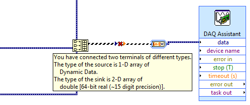
How to use generate multiple signals on a single DAQ Assistant
I am trying to generate several AO on my DAQ card, but I kept getting an error. I looked at the error and he said that I had to use a single DAQ Assistant. So, I created one, but I can't understand how to connect the signals. I get lines that don't connect. Is attached a picture of the installation. Thank you!!!
If you want to use the type of dynamic data, you must use the appropriate function. Do not use the construction. Use the Signal to merge. Then wire you the output of said directly to the Assistant.
-
Generate a signal FGEN 5421 and gettting on FScope 5122
Hello
(1) I need to generate a given signal
A [Sin (WT) + N * Sin (2Wt + pi)] by using PXI or 5421.I join the program that I created using Labview.The problem, I face by using this program, is that the maximum amplitude I can get is 1. Second thing, it is that I need to build only for some periods.
Later, I would like to make a sweep of this signal in the frequency range of 304kHz to 372kHz with a 0.5 kHz step size. How can I go about it?
(2) I'll send this entry signalinto my system and I am able to see the answer on the oscilloscope using the NI Scope front. I would like to know how I can use a labview program and acquire my answer with adequate sampling.
(3) I also need to convert the answer on my oscilloscope in a table of values so that I can import the table and generate the response in Matlab. How can I get the answer as a text file with a table of values?
Waiting for your response,
Thanks in advance,
David
I was wrong on my advise on the frequency sweep, kick these:
http://zone.NI.com/DevZone/CDA/EPD/p/ID/3327
-
How to set the output meter channel to generate a signal pulse using DAQ6008
Hello there I am generating a pulse signal of 100 Hz and a duty of 20% of the 6008 data acquisition cycle using visual studio 2013. I have code that needs to generate this but I'm not sure on how to set the channel output meter. When I run this NI MMAX and my vb error code indicates that the physical channel is not supported. I am a user of data acquisition were first and would appreciate any help offered.
If you look at the USB-6008/6009 User Guide and specifications, you will see that the counter in these devices cannot rely as edges of entry. It cannot generate a pulse.
Lynn
-
DAQ traditional and generator of signals of NOR-5401
We have an older system using a signal generator of NOR-5401 (S/N 183962E-40) that runs with FGen 1.5.1 and 7.1 of NOR-DAQ
We just bought an another NOR-5401 (S/N 192888 A - 01) to install a second system. However, it does not work with the software. The software uses traditional DAQ. If I look in MAX, the NOR-5401 on the new system only comes in the DAQmx instruments. On the old system, the NOR-5401 is available as traditional DAQ.
If I install an earlier version of the FGen (2.0 is the oldest, I can find) and NOR-DAQ 7.1 then the PC does not find a driver for the new OR-5401 at all.
Should what versions of FGen and NOR-DAQ I install to make it work?
Kind regards
Keven.
-
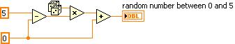
Generating the signal as shown in the picture in labview
Hello
I'm using labview in 2011 and want to generate the second signal as shown in the picture attached in labview as I want to use it as input to implement adaptive filtering, if the first signal in the image represents the output of the adaptive filtering area.
May I know how to generate a second signal.
Thank you.
-
How to connect the generator of signals of Agilent N9310A chauffeur?
Hello
I have a N9310A of Agilent connected via USB to a system using Labview 8.2 and the Agilent driver. The system goes into remote mode, so there is a communication. I tried to change the example of "Agilent N9310A RF Output" to exit BF (low frequencies) so that I can check the control of the signal using an oscilloscope gererator. I get the following error: Hex 0xBFFF0015 timeout expired before the operation is complete.
I must then disconnect and reconnect the USB cable that the example can not find the device. What happens here?
I'm new to using Labview with tools
-Thanks for any help
-Matt
Thanks for your help guys. The problem ended up being with the firmware of my Agilent N9310A signal generator. I got the A.02.03 firmware version and an upgrade to the current version (A.02.05) fixed something called an unstable connection between the PC and the N9310A.
This works.
-Matt
-
Generating a signal 10-bit via USB-6363
Greetings,
I need to characterize a 10-bit DAC at work using Labview and NI USB-6363. I have very little experience using Labview and need of a direction for this task. We are only interested in the INL and DNL. What I have in mind is to show the binary signal 10 to the DAC. Output of the DAC will a digital multimeter which is related to the USB connection to Labview via IEEE-488.
I have all this configuration, I just get lost with the way to do this in Labview. Thank you!
Hi joeyjojo,.
The USB-6363 use daqmx as mentioned Jason library. A good overview of the daqmx driver can be found here. Looks like you have the digital generation. Definitely check the examples that Jason sent you... especially one called write digital channel.
Use of the DAQmx write VI to set up the device to read a digital 2D U32 NChannel NSample. This will take in a table where each row corresponds to a new channel and 2D each column is a new sample. You can also view the daqmx help to get a better explanation of Scripture Daqmx. "To access help daqmx you, just go to help" using LabVIEW. In the Heirachey, to open VI and function reference' live action e/s and functions"DAQmx - live acquisition of data and functions" additional information and there will be a section in there about DAQmx write.
The best idea would probably be to start coding and let us know if you get some error. In addition, if you have never used LabVIEW, he could search in our DAQ and LabVIEW training. Keep us how we can help!
-
How can I generate sine signal long 10ms?
Hello world
I would like to do next: generate a sine or a DC signal for a period of time, 10 ms, that is to say after that, I want that my trips to Earth, so that the next time that I run the program. I use DAQ Assistant and DAQ 6211.
Any help or advice will be great!
Best regards
Pero
pero_kr wrote:
Let's say I have a while loop in my program. When I press "run" the loop runs over and over again, until the stop condition occurs. How long (in milliseconds, microseconds or nanoseconds) takes to my PC to do the operation in an iteration of the loop?
Hope this time was make myself clear. Thank you much for the help.
That depends entirely on what is inside the loop, and what does your computer and what operating system you are using. You cannot create a deterministic loop with a non-deterministic operating system like Windows. An iteration of the loop could take 5 msec, or it might take 5 seconds if the OS thinks it must go off and do something very important, like updating your computer to solve all these security holes that has Windows. You can use call loops, but those who are not guaranteed to operate at exactly the specified frequency since you are at the mercy of the operating system.
I still don't see why this information is important to you. Did you do as suggested and watched the examples supplied with LabVIEW and settle with DAQmx? They show you how to do the generation continues.
-
value of property not generating a signal event node
I have a sample program that uses a property node > Value (Signaling) to generate an event. The property looks like this:
When I create a VI to do the same thing, the property node looks like this:
I click with the right button on the Boolean control, create, node, value property (Signaling) to create the node.
My VI does not generate an event when a value of TRUE is passed to the property node. Is it possible to change the Boolean Data Type? What is the problem?
shall12 wrote:
My VI does not generate an event when a value of TRUE is passed to the property node. Is it possible to change the Boolean Data Type? What is the problem?
If the data type of the property value node does not resemble boolean (i.e. purple instead of green), you must change the mechanical action of the Boolean because it is currently latch action. Change the mechanical action to switch the action and you should be OK.
Also note that a value property (sgnl) fires the event to change value unconditionally, even if a new value of the former are the same.
(If you want to be able to raise Boolean lock action events as you describe here, consider a vote for this idea.
 )
)
Maybe you are looking for
-
Can Apple Watch returns a message that was not delivered
Periodically a message could not be sent, which is a problem in itself. However I wonder if there is a way to send back what she just came with a warning sign that it was not distributed. This message does not appear on the phone, so it will just b
-
Satellite C660-1NX freezes while stop after a new install of Win 7
Hello! The first sorry for my English, I'm Spanish and use a translator. I have a Satellite C660-1NX (PSC1LE-00F00NCE), I had to reformat the computer, put on a clean Windows 7 64 x (no recovery) with all the original drivers giving the official page
-
More HP Deskjet 2050 j510 series prints
None print desde that cambio of tinta y config
-
Also how do I install it? Just to be clear, this is a CAR I NEED NOT of RAM. I have an Acer Aspire 5100.
-
New IPad airprint can't find the Officejet Pro 8500 A909g series with firmware DLM1FN1006BR
The series Officejet Pro 8500 A909g with firmware DLM1FN1006BR is satisfactory airprint on the new IPad? If not, is there any difficulty?