Connection diagram missing in DAQ Assistant generate the signalling block
This is my first post so please excuse the quality of my description.
When I double click on the block of data acquisition - Assistant, there is no tab connection diagram I can access to see how things are wired to the top. I have a NI USB-6211 connected by USB and it is used to control many different sensors and a power supply. Currently, he works for everything and is hard wired correctly, but only blocks DAQ Assistant has a connection diagram available, the other are not. One who has a connection diagram is used to measure a voltage. Others who do not are used to generate a signal. I would really like to be able to see patterns of connection for each block.
-Any help would be appreciated
-Thank you
You can always do like those who never use the DAQ Assistant and read the manual. Right click on the device in MAX and selecting "stitching of the device" works too.
Tags: NI Hardware
Similar Questions
-
New Daq with the Daq Assistant in the filtering code
Hei,
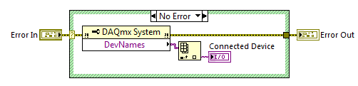
I have a NI USB-6225 DaqMx I used a couple of years. When I started with LabVIEW, I found the Daq Assistant to the best way to measure the voltage with my Daq etc. My company has purchased another DaqMx NI USB-6225 and now I have a big problem: the Daq Assistant in my old Vi does not work with the new data acquisition. I understand why there is this problem, but I do not know how to solve. I found this code on the forum who finds that Daq is connected:
The problem is that Daq Assistant do not have an entry for it, and it gives me an error if I try to run the code with a different device than the original, I used when I created the code.
Is there a way to solve this, so I don't have to convert all the Assistants Daq normal code?
Hello again,
two options:
(1) as the old software is related to 'Dev1' you must rename your new device to this alias and skip/rename the old device (and lack).
(2) rewrite your old software does not become is not dependent on the name of the alias for the data acquisition card...
It's your choice!
-
DAQ Assistant acquires the data into segments
I'm writing a code that reads and records the voltage, temperature and pressure on a cdaq-9174 using or 9221 and cards or 9173. The problem is that when the daq assistant is set to N samples outputs the data blocks in the graphics. I wish it were a continuous stream so I can see what is actually happening. I tried to change continuously, but it gets an error or is has data about 16000 points in 10 seconds, which is a lot more that I prefer. The code I am using is borrowed from another person and then the installation exactly it works on this computer, but not mine. Does anyone have any suggestions on how to solve this problem. I enclose the code as well as the sub live he uses.
Thanks for all the help. I didn't know at first that the NI 9237 card has a minimum sampling rate of ~ 1600 Hz. I am now able to taste to 2000 Hz then use decimating continues to write in my file at 200 Hz.
-
Second DAQ assistant in the power control system does not
Hi all
I need your help on this issue. I'm currently programming a VI for one command power supply for pool boiling experiments. The organizational structure of the VI program is attached.
I use two assistants DAQ for steady-state acquisition and temperature unstable state data respectively. The first assistant DAQ (samples to read 5, 5 Hz rate) for the acquisition of works unstable state data well (see the attached image file first DAQ Assistant for acquisition of temperature unstable state). The second assistant DAQ (samples to read 12 k, 200 rate) for stationary data acquisition does not work (please see attachment image Second Assistant DAQ of steady-state temperature acquisition), showing only a series of data files size of 1 KB with no data on the inside. And indicators for steady-state data also revealed nothing.
After a similar Q & A search in the forum, I tried to distribute different channels for 1 and DAQ assistant 2. However, the situation was almost the same.
The material I used are chassis SCXI 1000 and SCXI 1303 Council to acquire thermal couple temperature data. Food was AMREL SPS200-50-K025. LabVIEW software is the 2014 version.
I had just started to learn LabVIEW for only a month, and I know that the VI is a little messy. Hope you guys can also give me some advice on how to improve this VI.
Have you looked at the error on the second daq assistant? You will see that a reserved resource error because you cannot use two different assistants. You do not mention the real DAQ hardware but there a clock unique convert. You can use only one assistant with a unique sampling frequency.
-
DAQ Assist and the graphic representation
A very simple problem...
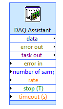
Very new to LabView, and I fight with wiring to the top of my Daq Assistant, in order for a chart data of a load cell. I have plugged my scale to the acquisition of data and you want to measure strength readings over a period of time / when I press stop. When I run my program it graphic only a finite number of readings and then clears the graph to copy the new readings on top. I put my chart outside the while loop so that it would be graphic a reading at the same time as they were read, but it does not work. If my son is not what is wrong, I feel that my time parameters for the Daq Assistant is not appropriate (and I do not know how to set those either.) I don't understand the description/effects rates and samples to read.
Thanks for your help.
AFLR wrote:
A very simple problem...
Very new to LabView, and I fight with wiring to the top of my Daq Assistant, in order for a chart data of a load cell. I have plugged my scale to the acquisition of data and you want to measure strength readings over a period of time / when I press stop. When I run my program it graphic only a finite number of readings and then clears the graph to copy the new readings on top. I put my chart outside the while loop so that it would be graphic a reading at the same time as they were read, but it does not work. If my son is not what is wrong, I feel that my time parameters for the Daq Assistant is not appropriate (and I do not know how to set those either.) I don't understand the description/effects rates and samples to read.
Thanks for your help.
Hi, AFLR,.
I think the settings are fine, you have defined DAQ to read 100 samples at a rate of 100samples per second, you will get 100 samples per second.
Now to maintain the previous data in the graph (which is not the nature of the chart), you will need to keep by writing additional code.
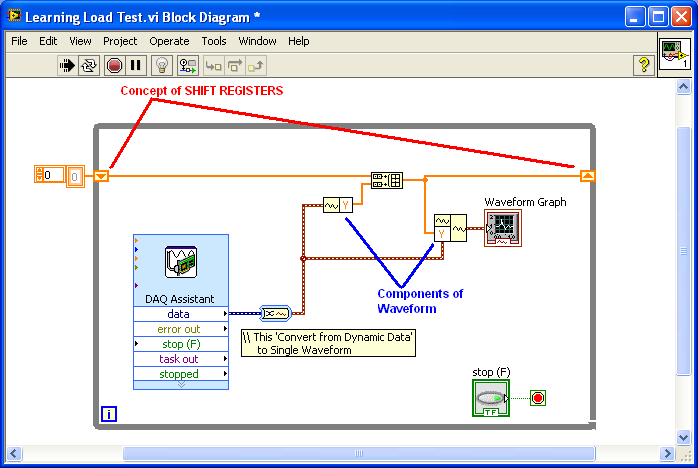
If you already know:
1. SHIFT registers and
You can easily implement this requirement, find the attached VI for your reference.
-
Generating the signal as shown in the picture in labview
Hello
I'm using labview in 2011 and want to generate the second signal as shown in the picture attached in labview as I want to use it as input to implement adaptive filtering, if the first signal in the image represents the output of the adaptive filtering area.
May I know how to generate a second signal.
Thank you.
-
Connecting to a site locked/secured generates the warning?
I check my email from Verizon via the Web, the login procedure has the gray padlock. However, according to the latest update of Firefox, try to sign in site results in the following security warning: "Although this page is encrypted, the information you entered is to be sent over an unencrypted connection and could easily be read by a third party." Two response buttons are available: continue and cancel.
I hope that my memory is not faulty, but I do not remember the past never before. Is there a bug in the version of Firefox that I use, maybe?
Yes, I have already restarted Firefox. I even rebooted my system. The problem remains, however.
Thanks in advance for any info you can provide.
See this thread:
-
generate the signal of decimal number
Hello
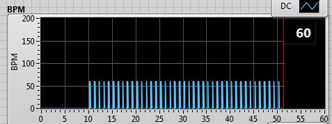
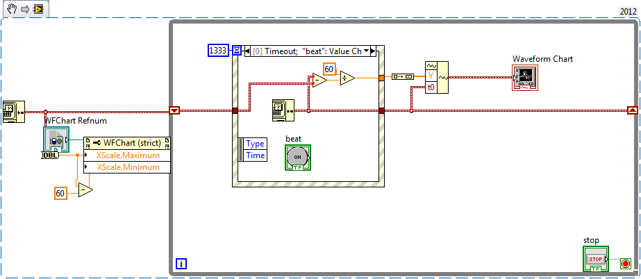
I have a program that calculate the heart rate from the ECG signal. I want to show the beats per minute on a graph with 60 s of the plot of the story.
Since the vi who calculate the heartbeat I get output the string with the number, only when the wave of the tip, then I convert it to a number and then I place the offset of a simulated DC signal.
(In the table below the beats per minute are always 60 because I'm simulating a sinusoidal signal with 1 Hz).
------>
It works fine, but I'd like to see not the summits but a continuous line from one point to another, such as interpolation.
in this case, it would have been a horizontal line to 60 BPM.
I thought to store the last value of the chain and keep it frozen until the next update of value.
Do you have suggestions on how to do it?
Concerning
Not clear what you get in the form of numbers, seems that you get too many zeros, and you get a decimal number or another 'dynamic '? value?
You pulse-rate information could be ~ 45 to > 180 values per minute!
You display the exact story of a minute? Maybe (keep the last ~ 300 values with timestamps and use an XY diagram) a graphic story can be configured to display
wait... Here's one way:
I fed a chart (with 256 points in history), with a waveform. the wfrm has only a single value in the array of values and a t0. The chart is configured to display the 60 sec. Seems to work
My simulation will display a min rate of ~ 45 BPM, but you can beat him

-
generate the signal f = 50 Hz with NOR-9264
Hello. I am Sorin.
I need to generate a sinusoidal waveform with f = 50 Hz, U is 3Vrms. I have a C, OR-9264 module. Is it good? Or can it only generates SCR?
I don't have C modules: I for RTD, V, mA, universal and AO for V and mA.
What can I use?
Thank you.
It DOES not say that it displays up to 25 kech. / s (25000 samples per second). It's more than enough for 50 hz.
-
Big latency constant to generate the signals AO which is an immediate copy of the signals HAVE.
-
Internet
Most often when a device is not it's because of a driver. Try reinstalling your.
It works for win 7 & 8
http://Windows.Microsoft.com/en-us/Windows7/update-a-driver-for-hardware-that-isn ' t-work correctly? SignedIn = 1
http://captaindbg.com/how-to-update-drivers-on-Windows-7/
-
Simulate signals wired to the DAQ assistant for USB-6009 device
Hello
I'm trying to send a signal to the DAQ Assistant Express VI. I watched the movie "Generating a Signal" on the Web site of NOR (www.ni.com/academic/students/learnlabview/generate.htm) and I have my Signal simulate connected directly on the DAQ Assistant, as shown in this film. In my case, the DAQ Assistant sends the signal to a device USB-6009.
However, I received this message:
Error-200077 occurred to the DAQ Assistant
Possible reasons:Requested value is not supported for this property value. The value of the property may be invalid because it is in conflict with another property.
Property: SampTimingType
asked the value: Sample clock
You select: On-demandIf I select 'On Demand' in my DAQ assistant and run the vi everything works beautifully. However, I need my DAQ assistant to be configured to generate a waveform AC continuous, not output a single alternating current rippling.
What happens here? I did not have this problem before on other devices of NOR. I am using LABView 2010.
Please answer.
Thank you.
-
How can I programmatically change the parameters of voltage range in a DAQ Assistant
Hello
First post here.
I need to be able to change the properties of voltage range of a daqmx assistant DAQ based on user input. My material, an SCXI module - 1102C does not change this property on a running task, so I would together the range of input voltage analog before activating the DAQ Assistant, or break the DAQ Assistant immediately after it starts, set the values, and then resume.
I don't know how to change the task ahead because the DAQ assistant creates the task when it is running, and there is no job before that.
In the attached photo, I have a conditional section, configured to run only if the loop iteration is 0. I take the task of the Daq assistant, sending him stop vi of task, set the property and then send the task with the snap the vi task. I can watch him run with lightweight debugging on, and everything seems to work properly, but on the second (and all others) iteration of the loop, I read I. Max and it seems that a re DAQ Assistant set it to the 5V. You can see what's going wrong here?
BTW, there is a continuous acquisition and the code doesn't produce error messages when executing.
I've encountered a similar question someone posted here in 2006, but his question was specifically a Labview API (VB, I think) and not a real solution of G.
Attached are the real vi in question and a PNG of the block diagram.
Thank you!
Ruby K
First of all, if you want to start getting beyond the basics with the DAQ hardware, you have to stop using the DAQ assistant and do it with lower level VI DAQmx. There are hundreds of examples in the finder of the example. You can even make a right-click on the DAQ assistant and select open front panel. This will create a Subvi, you can open and see what is happening behind the scenes. Do it. I think you will find that the task DAQ is recreated on each (although I'm not 100 percent the way parameters are established or maintained in each section of this sub - VI).
The second problem is that you have a bit of a race on iteration 0 condition. These two property DAQ nodes are running at the same time. Thus, when you read the AI. Max, this can happen before or after the AI. Max is located in the structure of your business.
Thirdly, make sure that involve you your son of the error.
-
Hi all
This should be a pretty simple question, but I can't seem to find the answer online and currently do not have the functionality to test this:
I'm using LabVIEW 8.5 and have a VI that imports data from sensor through the DAQ Assistant. In the configuration tab, there is a range of signal input. What happens if my sensor exceeds this range? I get a warning? The default value is the maximum (or minimum)? I was interested in writing a code to display an error that I approach the limits of this range, but did not know if I also need to include code to display an error if the scope is exceeded as well.
Thanks for the help,
Tristan
Hello, Tristan,.
The behavior depends on the selected range and the device you are using.
If you are using a device with a single input range is valid, we will use this range, even if you set a smaller minimum and maximum in the DAQ Assistant. So, if your device only supports ±10V and you set the range to ±8V, you will still continue to get valid data after your top sensor 8V until what you approach 10V. When you reach the limit of the extent of your device, the output will be 'rail', and simply return the maximum value until the signal is less than the maximum value again.
Note: A device that is nominally ±10V usually has a go-around (such as ±10.2V) which are usually specced in the manual.
However, if you use a device with several ranges of entry then things become more complex.
NOR-DAQmx player will choose the smallest range that entirely covers the interval you choose. For example, suppose that your device supports the following input range: ±0.2V, ±1, ±5V, ±10V and you choose 0V - 3V as the range in the DAQ assistant. The NOR-DAQmx driver will focus on the input range and the list of the entry lines that your hardware supports and choose the smallest encompassing the entire range that you set. This would be the ±5V, because this is the only beach that contains up to 3V. Thus, all between ±5V input signal is returned and none outside this range will be 'rail' to the maximum or minimum value.
We do this because using small beaches make more efficient use of the resolution of the ADC. So, we try to use the most effective range based on what you ask without picking up a range that will make you miss data.
Let me know if I can clarify it more.
-
Starting assistant DAQ prior to the main version of the program
Hello
I would need to begin to acquire data via the module Wizard DAQ 100ms before my main program in the while loop starts (see attached photo). How could I just realize this (without having to include the DAQ assistant in the while loop itself)?
Thanks for your help,
Thibault.
Put a picture of flat sequence between the beginning of mx DAQ and the while loop. Connect the wires of error through it. Put a wait 100 ms function in the frame.
Maybe you are looking for
-
Urgent: need help on problems on the iPhone after updating iOS 10 6s
Hey there! It's my third post about the problems Ive been face on my devices after 10 updated iOS. Initially, after that I've updated, the music app was not running on my phone-all I could see was an empty screen and the APP crashed and I was redirec
-
To open multiple windows, not tabs; Don't let me.
I have Windows XP. Since I've upgraded to 7.0.1 (and today 8.0) I was not able to open multiple windows of Firefox. I did check TABS instead of WINDOWS, but Firefox open or anything, when I try to start a 2nd window of he or she opens a tab. Please f
-
Password forgotten on old Tecra 510CDT
I hope someone can help out me. I have an old Tecra 510CDT and you have forgotten the password. The system starts and past by memory to initialize the screen then request a password that i have forgotten. Is there a way to get around this?I hope some
-
Satellite L300D - need help to check if the adapter fits
My adapter for my * Satellite L300D - 11A system unit * recently broke and the laptop will not load. I am resonably sure that the adapter is broken as the power to the adapter cord works, but the adapter for the laptop does not work. I found somethin
-
My Acer V3-4729-32RJ kind of resets?
I need help. I turned on my laptop today and this message appeared near the clock. I don't know why it appeared. I always shut down my computer the right way (go to the start menu and click close). Now all my files are still there, but my Start menu